A Review: Implementation of Maximum
Power Point Tracking Algorithm for PV
System on FPGA
Nikhil A. Gawai
1, Prof. N. M. Wagdarikar
2PG Student [VLSI & Embedded System], Dept. of ECE, SKN College of Engineering, Vadgoan (bk), Pune, India 1
Assistant Professor, Dept. of ECE, SKN College of Engineering, Vadgoan (bk), Pune, India 2
ABSTRACT: Photovoltaic power generation has two major problems: the conversion efficiency of existing PV modules is less and amount of power generated by PV system changes with weather conditions. Also, the PV cell I-V characteristics are non-linear due to complex relationship of voltage & current and varies with change in temperature or insolation. There is only one point on P-V or I-V curve called Maximum Power Point at which PV system operates at maximum efficiency and produces maximum output power. Failure to track MPP causes significant power loss. So, Maximum Power Point Tracking (MPPT) is required to operate PV system at MPP. The P&O algorithm and INC algorithm are commonly used methods to track MPP by adjusting duty cycle of DC-DC converter. The existing methods use microcontroller or DSP controller to implement MPPT algorithm. FPGA provides number of advantages over sequential machine microcontroller, as FPGA does concurrent operation i.e. instructions executed continuously and simultaneously. However DSP does signal processing related calculation only. Using FPGA number of components required is less and FPGA is faster than DSP. Thus, the size of components required for power converter decreases. The MPPT algorithm is implemented on FPGA which continuously track the maximum point under rapid environmental changes.
KEYWORDS: Photovoltaic System, MPPT, P&O Algorithm, Incremental Conductance Algorithm, DC-DC
Converter, FPGA.
I.INTRODUCTION
A MPPT, or maximum power point tracker is an electronic DC to DC converter that optimizes the match between the solar array (PV panels), and the battery bank or utility grid. To put it simply, they convert a higher voltage DC output from solar panels (and a few wind generators) down to the lower voltage needed to charge batteries.
Maximum power point tracking (MPPT) is a technique that grid connected inverters, solar battery chargers and similar devices use to get the maximum possible power from one or more photovoltaic devices, typically solar panels, though optical power transmission systems can benefit from similar technology. Solar cells have a complex relationship between solar irradiation, temperature and total resistance that produces a non-linear output efficiency which can be analyzed based on the I-V curve. It is the purpose of the MPPT system to sample the output of the cells and apply the proper resistance (load) to obtain maximum power for any given environmental conditions. MPPT devices are typically integrated into an electric power converter system that provides voltage or current conversion, filtering, and regulation for driving various loads, including power grids, batteries, or motors.
Solar inverters convert the DC power to AC power and may incorporate MPPT: such inverters sample the output power (I-V curve) from the solar cell and apply the proper resistance (load) so as to obtain maximum power.
MPP (Maximum power point) is the product of the MPP voltage (Vmpp) and MPP current (I mpp): some solar panels have a higher maximum power than others.
is introduced between the photovoltaic module (PV) and the load, constituting a photovoltaic conversion chain, to achieve this goal. The literature proposes many MPPT strategies which guarantee to work to the Maximum Power Point (MPP) of the I-V curve of the PV array. But, in practice there are numerous factors which cause the actual operating point to vary from the true MPP. For example, the MPPT commands that use search algorithms which oblige the operating point to oscillate around the MPP (Perturb & Observe).
Control systems become ever more complex and multitasking, hence the need to use control systems by FPGAs. For the MPPT control, we can see in the literature several techniques for finding the maximum-power point as P&O, Hill-Climbing, Fuzzy Logic or Neural Methods. But these sequential techniques are not yet well adapted for FPGA implementation. So, the aim of our works is to explore and develop an accurate and robust MPPT control with a minimum FPGA implementation size.
II. RELATED WORK
1. Renewable Energy & Solar Energy
Energy is required for our life and economy. As the country develops it needs more energy. Now days energy is supplied by burning fossil fuels such as coal, diesel. Increased energy demand results in two problems: energy crisis and climate change (global warming).The worldwide energy demand increases, the energy related green house gases emission increases. It is global challenge to reduce the CO2 emission and provide clean, sustainable and affordable energy.Energy saving is one cost effective solution but does not tackle the worldwide increasing energy demand. Using Renewable energy is good option because it provides clean and green energy, with little or no CO2 emission. Renewable energy is generated from renewable energy sources such as Solar emission, Wind, Tides, geothermal etc. The major renewable energy technologies are Hydropower, wind power generation, biomass and ocean energy. This energy is used in Power Generation, Rural electrification (off-grid) and as transport fuels. Compared to fossil fuels Renewable energy has many advantages. Firstly, the Renewable energy obtained from natural sources so it is sustainable and it will not emit CO2 gas. So renewable energies tackle the green house effect and also provide sustainable energy. To achieve the renewable energy target, more funds will be provided in research and development of renewable energy.
2.Solar Energy
Solar energy is one of the important sources of renewable energy. The sun radiates large amount of energy which is enough to satisfy the need of whole world. Solar energy is used for providing heating, cooling, light and for electricity. One of the important technologies is Photovoltaic (PV), by photoelectric effect the sunlight is directly converted into electricity. In 1839 the Edmond Bequerel found the photoelectric effect accidently while working on solid-state physics.1n 1883 Fxitz fabricated the first thin film solar cell. In 1941 ohl fabricated silicon PV cell but that was very inefficient. In 1954 Bell labs Chopin, Fuller, Pearson fabricated PV cell with efficiency of 6%. In 1958 PV cell was used as a backup power source in satellite Vanguard-1. This extended the life of satellite for about 6 years. The cost of large scale PV system installation is high compared to conventional energy systems for same energy production. The research is going on to reduce the installation cost of large scale power generation and to increase the efficiency of PV system.
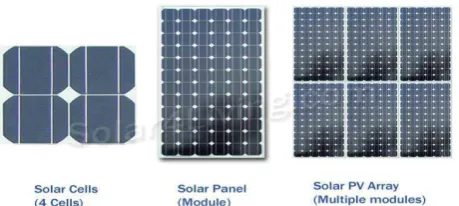
PV Cell: The smallest, basic photovoltaic device that converts radiation directly into electricity. Each PV cell is rated for 0.5 - 0.7 volt and a current of 30mA/cm2.Based on the manufacturing process they are classified as:
Mono crystalline: efficiency of 12-14 %. They are now predominantly available in market Poly crystalline: efficiency of 12%
-Amorphous: efficiency of 6-8%
Life of crystalline cells is in the range of 25 years where as for amorphous cells it is in the range of 5 years.
PV Module: Series and parallel connected solar cells (normally of 36Wp rating).
PV Array: Series and parallel connected PV modules (generally consisting of 5 modules).
4. I-V Characteristics of PV Cell
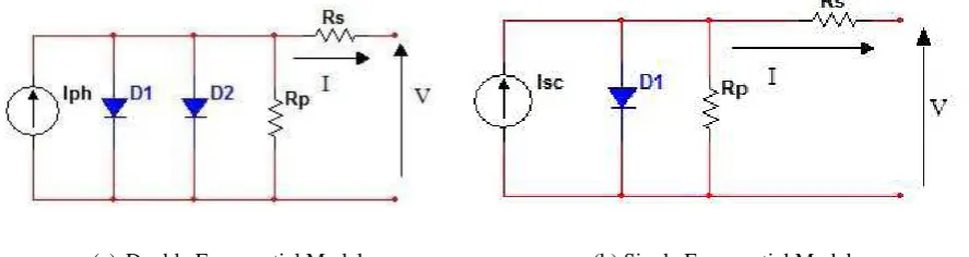
Fig 2 shows two electrical equivalent models of PV cell derived from the physical mechanism of PV cell. The first model contains two diodes that reflect diffusion and carrier recombination. The second model is a simplified providing similar characteristic for the representation of PV cell.
(a) Double Exponential Model (b) Single Exponential Model
Figure 2: Electrical Equivalent Circuits of PV Cell
𝑰 = 𝑰𝒑𝒉 − 𝑰𝒐𝟏 𝒆𝒒 𝑽+𝑰 𝑹𝒔 𝒌𝒕 − 𝟏 − 𝑰𝒐𝟐 𝒆 𝒒 𝑽+𝑰 𝑹𝒔
𝒏𝒌𝒕 − 𝟏 −𝑽 + 𝑰 𝑹𝒔
𝑹𝒑 … … . (𝟐. 𝟏)
𝑰 = 𝑰𝒑𝒉 − 𝑰𝒐 𝒆𝒒 𝑽+𝑰 𝑹𝒔 𝒏𝒌𝒕 − 𝟏 −𝑽 + 𝑰 𝑹𝒔
𝑹𝒑 … … … . (𝟐. 𝟐)
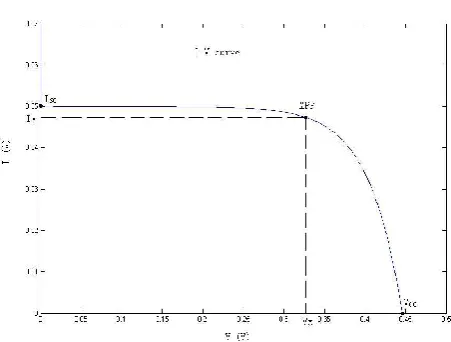
The I-V characteristics of PV cell shown in fig2.3.The double exponential model eqn1.1 and single exponential model eqn1.2 are used to characterize the PV cell. A PV cell behaves differently depending on the size/type of load connected to it. This behavior is called the PV cell ’characteristics’. The characteristic of a PV cell is described by the current and voltage levels when different loads are connected.
Where,
V =PV cell terminal voltage (V) I = PV cell terminal current (A) Iph = photocurrent (A)
Io1 =saturation current due to diffusion mechanism (A)
Figure 3: Typical I-V characteristics of PV Cell Io = saturation current (A)
Rp = cell shunt resistance (Ω) Rs = cell series resistance (Ω) ƞ= p-n junction ideality factor q = electronic charge =1.6 × 10⁻¹⁹C
k = Boltzmann’s constant =1.38 × 10⁻²³ J / K T = junction temperature K
5. PV System
PV Modules and Array
PV source is scalable means it can be used from mW for solar watches, solar calculators to MW in large plants to provide power to utility grid. Depending on the cell area, the output current from a single PV cell can be used directly. However, its output voltage is usually too small for most application hence to produce useful DC voltages, a number of PV cells are connected in series and mounted in a support frame, which forms a PV module (or a PV panel).
To generate higher currents and/or voltages, PV modules can be connected in series and/or in parallel to form a PV array for higher power applications. Bypass and/or blocking diodes are often used in a PV array to reduce power loss when one PV module generates less photocurrent.
PV system topologies
There are 3 types of PV systems: 1. Stand-Alone system
2. Grid connected systems 3. Hybrid systems
(a) Off-Grid PV system (b) Grid Connected PV system
Figure 4: PV system topologies
III. PROPOSED METHODOLOGY
1. Maximum Power Point Techniques
Broadly the MPPT methods are classified in two types;
Indirect method: Maximum power point is estimated from various parameters such as voltage, current, irradiance temperature, using empirical data or using mathematical expression. This estimation is carried for specific PV system. Some of these techniques are:
Curve fitting method
Lookup table method
Fractional OC method
Fractional SC method
Direct methods: This technique does not require any prior knowledge about PV panel and are independent of temperature, insolation or degradation levels. They use voltage and/or current information about PV to track MPP. These techniques are computationaly intensive. Some of these techniques are:
Pertub and Observe /Hill climbing Method
Incremental Conductance Method
Fuzzy Logic Control
Sliding Mode Control Method
2. Proposed Block Diagram
The main purpose of this project is to implement Maximum power point algorithm in FPGA which will provide more advantage than DSP processor or microcontroller. This algorithm will be installed on a controller. The controller will be implemented on an FPGA (Field Programmable Gate Arrays) and designed through a computer using graphical programming language called LabVIEW. The programmed FPGA will be able to automatically control the whole power system operation without the need of any user intervention.
The sampling Circuitary is used to convert voltage and current from analog to digital. The proposed system consists of Boost type DC/DC power converter, which is controlled by an FPGA-based unit using the Pulse Width Modulation (PWM) principle.
Figure 5:Block Diagram of Photovoltaic System
III.ALGORITHMS
1. MPPT Algorithm
PV module would have a maximum power point for given temperature and insolation. If a load line crosses at this point, maximum power would be transferred to the load. When temperature or insolation changes, maximum power point changes. Since the load line does not change, it does not pass through the maximum power point and hence maximum power cannot be transferred to the load. To achieve the transfer of maximum power, it requires that the load follows the maximum power point and this is achieved by translating the actual load line point to maximum power point by varying the duty cycle of DC-DC converter. We can vary the DC-DC converter duty cycle (D) manually to operate PV system at maximum power point (Vmpp, Impp). As the temperature and incident solar radiation changes throughout the day we should have to set duty cycle (D) automatically to track the maximum power point automatically. There are various techniques which adjust duty cycle (D) automatically which can be implemented in analog or digital method.
Figure 6:Load Line and Operating Point
2. Pertub & Observe Algorithm
are four cases. To determine whether the duty cycle of the gate signal should be increased or decreased. The four cases are shown in Table
The first case, when both power and the duty cycle is increased, the duty cycle should continue to increase toward the MPP. Second Case is similar except the duty cycle should continue to decrease toward the MPP. Cases three and four occur when the power has decreased, so the duty cycle has moved the PV voltage away from the MPP. The duty cycle is reversed. It is decreased in case three and increased in case four.
Table 1: Summary of Hill Climbing and P&O Algorithm Perturbation Change in Power Next Perturbation
Positive Positive Positive
Positive Negative Negative
Negative Negative Negative
Negative Positive Positive
The system oscillates around MPP. The oscillations are minimized by decreasing perturbation step size. But decreasing perturbation step size slows down MPPT algorithm. Variable perturbation step size gets small time to track MPP. MPP toggles between traditional hill-climbing algorithm and modified adaptive hill-climbing method to avoid deviation from the MPP. P&O method may result in top-level efficiency, when a proper predictive and adaptive hill climbing strategy is implemented. Hill-climbing and P&O method can fail under rapidly changing atmospheric conditions.
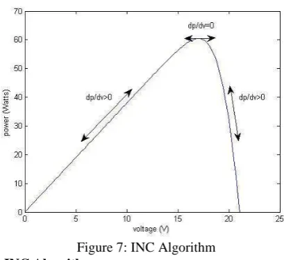
3. Incremental Conductance (INC) Algorithm
Incremental Conductance (INC) is the second MPPT algorithm possibility for this project. In cases of rapidly changing atmospheric conditions, as a result of moving clouds, it was noted that the P&O MPPT algorithm deviates from the MPP. Avoiding the P&O algorithm drawbacks formed the basis of the INC Conduction algorithm in which the array terminal voltage is always adjusted according to its value relative to the MPP voltage. At the MPP the derivative of the power with respect to the voltage is zero because the MPP is the maximum of the power curve (i.e slope of P-V curve at MPP is zero). We note that to the left of the MPP the power is increasing with the voltage, i.e. dP/dV > 0 (slope is positive), and it is decreasing to the right of the MPP, i.e. dP/dV < 0 (slope is negative).
Slope of PV Curve is
Zero at Maximum power Point
Negative on right of Maximum power Point
Positive on left of Maximum power Point
Figure 7:INC Algorithm 4. Comparison of P&O and INC Algorithm
However Incremental Conductance algorithm has increased susceptibility to noise and has increased complexity compared to P&O.
In INC Power loss occurs since it oscillates around MPP like P&O.
Tracking step size is value has significant effect on effectiveness of MPPT. When tracking step is chosen correctly, P&O will give performance equivalent to INC.
P&O is a very popular and widely accepted MPPT algorithm and simpler to implement than INC.
VI.CONCLUSION
Solar power continues to prove its potential as revolution for renewable energy. As companies continue research into the solar power, technology for them is becoming more and more useful. One of the main concerns for fixing problems involved with solar panel is of solar panel efficiency. A major goal for this solar panel application design was to optimize efficiency whenever possible. The P&O and INC algorithm proved to be more beneficial to track maximum power point, which increases the efficiency.
REFERENCES
[1] El Basri Youssef, Petibon Stephane, Estibals Bruno, Alonso Corinne, “New P&O MPPT Algorithm For FPGA Implementation”, Cnrs; Laas; Avenue Du Colonel Roche, F-31077, Toulouse, France. Universite De Toulouse; Ups, Insa, Inp, Isae; Laas; F-31077, Toulouse, France. [2] Sanam Rathnakumar, Burri Ankaiah, “Solar Photovoltaic Cell by using Incremental Conductance Method with MPPT Algorithm”, M.Tech
[EPE], Department of Electrical and Electronics Engineering, Global Institute of Engineering & Technology Chilkur (V), Moinabad (M), R.R (dist) Andhra Pradesh, India.
[3] Nicola Femia, Giovanni Petrone, Giovanni Spagnuolo, and Massimo Vitelli. “Optimization of Perturb and Observe Maximum Power Point Tracking Method”, Member, IEEE.
[4] Abdourraziq Mohamed Amine, Maaroufi Mohamed, Ouassaid Mohammed.” A new Variable Step Size INC MPPT Method for PV Systems”, Department of Electrical Engineering Ecole Mohammadia d'Ingenieurs, Mohammed V Agdal University, Rabat, Morocco.
[5] Ryan Shun-cheung Yeung, *Henry Shu-hung Chung, Senior Member, IEEE, and †Steve Tzu hsiung Chuang,” A Global MPPT Algorithm for PV System under Rapidly Fluctuating Irradiance”, Centre for Smart Energy Conversion and Utilization Research City University of Hong Kong Tat Chee Avenue, Kowloon Tong, Hong Kong
[6] CAI Wen-hao, LI Yun, LI Du,” Design and Application of Photovoltaic Battery Digital Simulator”, Xi’an University of Science and Technology Xi’an , China