Vol. 5, Issue 1, January 2016
Fly back Converter Using PV Source with
Modified MPPT Techniques for AC Load
Applications
D.Shanmugavel
1, M Kalaiselvi
2, S.Mohanram
3, M.Kalidasan
4Assistant Professor, Dept. of EEE, Pollachi Institute of Engineering and Technology, Pollachi, Tamilnadu, India1
Assistant Professor, Dept. of ECE, Pollachi Institute of Engineering and Technology, Pollachi, Tamilnadu, India2
Assistant Professor, Dept. of ECE, Pollachi Institute of Engineering and Technology, Pollachi, Tamilnadu, India3
Assistant Professor, Dept. of EEE, Pollachi Institute of Engineering and Technology, Pollachi, Tamilnadu, India4
ABSTRACT:Photovoltaic (PV) vitality presents awesome potential for applications in conveyed power frameworks. On the other hand, despite everything it exhibits a low vitality transformation rate even at the Maximum Power Point (MPP). The normal effectiveness can be even lower if the working point is permitted to float as indicated by uncontrolled burden and barometrical conditions varieties. Keeping in mind the end goal to boost the vitality change, power hardware converters controlled with Maximum Power Point Tracking (MPPT) calculations are utilized. Different sorts of MPPT calculations have been proposed in the writing. In PV creating frameworks, bother and perception (P&O) MPPT calculations are generally utilized. This framework depends on change of P&O strategy through a settled step prescient control by utilizing Model Predictive Control (MPC) under measured quick sunlight based radiation variety. The proposed prescient control to accomplish MPP speeds up the control circle since it predicts mistake before the exchanging sign is connected to the fly back DC/DC converter. This undertaking proposes the configuration of a battery which stores vitality and conveys to the heap when the PV source can't supply the ability to the heap. On account of the huge utilization of air conditioning stacks, a PWM inverter is associated at burden side to give air conditioning supply. It is relied upon to diminish the motions created. MATLAB/SIMULINK is utilized to recreate the model.
KEYWORDS: Maximum Point Tracking, Battery, Photovoltaic Array, Flyback converter DC-DC converter, Model prescient control, Voltage source inverter.
I. INTRODUCTION
ISSN (Print) : 2320 – 3765 ISSN (Online): 2278 – 8875
I
nternational
J
ournal of
A
dvanced
R
esearch in
E
lectrical,
E
lectronics and
I
nstrumentation
E
ngineering
(An ISO 3297: 2007 Certified Organization)
Vol. 5, Issue 1, January 2016
the issue of effectiveness and items utilizing these systems have been made and are currently economically accessible for purchasers [3]. Most extreme Power Point Trackers (MPPTs) assume a critical part in photovoltaic (PV) power frameworks in light of the fact that they augment the force yield from a PV framework for a given arrangement of conditions, and accordingly expand the cluster proficiency. Along these lines, a MPPT can minimize the general framework cost. MPPTs find and keep up operation at the greatest force point, utilizing a MPPT calculation. In the course of recent decades, numerous MPPT strategies have been proposed; the relative benefits of these different techniques are examined in [4]. The basic working administration is low insolation. Amid low insolation periods, catching the majority of the accessible sunlight based force can generously enhance framework execution. A viable MPPT controller and converter can utilize accessible vitality to essentially lessen the measure of introduced PV.
Considering the MPPT routines talked about in [4], strategies considered incorporate Incremental Conductance (INC), Perturb-and-Observe (P&O), fragmentary Open-Circuit Voltage (Voc), and Best Fixed Voltage.
The P&O system, asserted by numerous in the writing to be mediocre compared to others, keeps on being by a long shot the most broadly utilized technique as a part of suitable MPPTs. P&O is a surely understood system with moderately great execution; on the other hand, P&O technique can't generally focalize to the genuine most extreme force point. Additionally, P&O is moderately moderate, which restricts its capacity to track transient isolation conditions [1]. The primary commitment of this paper is to enhance the P&O strategy execution by anticipating the mistake one stage ahead in skyline through model prescient control method [10]. This proposes another usage of a P&O calculation that mitigates the primary disadvantages generally identified with the P&O system.
II. PROPOSED SYSTEM CONFIGURATION
Figure 1 shows a block diagram of the solar PV energy conversion system with a dc-dc fly back converter, a battery, a VSI and an output filter.
Fig. 1. Block diagram of system configuration
Fig. 2. Proposed arrangement of solar PV energy system with a flyback converter and a solitary-stage voltage source inverter
A. Battery System and Inverter
The battery plays an important role in case of the solar power system. The battery stores part of the energy generated by the solar PV power source and delivers to the load during the periods when the solar power source is unable to supply the power to the load due to any reason. The capacity of the battery depends on the daily load and days of autonomy. A full-bridge voltage source inverter (VSI) is utilized here which consists of four switches. PWM pulses are generated by the sinusoidal PWM controller. The output signal from this full-bridge VSI is a pulse waveform which contains the desired YIELD waveform along with frequency components at or around harmonics of the switching frequency. A filter is here utilized to extract the desired output voltage by separating it from the switching frequency.
III. PRINCIPLE OF MODEL PREDICTIVE CONTROL
By development technology of computer and digital signal processing, modern techniques have been developed for power converter controlled such as model predictive control (MPC) [5]. This control appears during 80s as an attractive alternative for the control power converter due to its quick dynamic response. The main characteristic of predictive control is use the model of system for prediction of controlled variables and selects the most appropriate control set based on optimality criterion. The different approach called Model predictive control.
MPC has capable of predicting future yield signals based on future input signals and initial values. A model of the system is considered in order to predict the future behavior of the variables over a period. These predictions are evaluated based on the characteristic of model and cost function, and then the sequence that reduces the cost function is selected to predict the future control signal.
In the general scheme of MPC for power electronics inverters measured variables , X(K) , are used in the model to calculate predictions, X̃1(K+1) of the controlled variables for each one of the n possible actuations, that is, switching states, voltages, or currents [1]. Then these predictions are evaluated using a cost function which considers the reference values, X1*(K+1), design constraints, and the optimal actuation, S, is selected and applied in the converter. The normal form of the cost function, g, subject to minimization can be formulated as
g = [X̃1(K+1) – X1*(K+1)] + λ1 [X̃2(K+1) – X2*(K+1)]+…+ λn [X̃n (K+1) – Xn*(K+1)] (1)
ISSN (Print) : 2320 – 3765 ISSN (Online): 2278 – 8875
I
nternational
J
ournal of
A
dvanced
R
esearch in
E
lectrical,
E
lectronics and
I
nstrumentation
E
ngineering
(An ISO 3297: 2007 Certified Organization)
Vol. 5, Issue 1, January 2016
IV. MPPT USING MODEL PREDICTIVE CONTROL
The technique Maximum Power Point Tracking (MPPT) is used in power electronic circuits to extract maximum energy from the Photovoltaic (PV) Systems [6]. In the recent decades, photovoltaic power generation has become more important due its numerous advantages such as needs a few maintenance and environmental advantages and fuel free. However, there are two major barriers for the utilization of PV systems, low energy conversion efficiency and high initial cost. To enhance the energy efficiency, it is important to work PV system always at its maximum power point.
A. Perturb and Observe Algorithm
In proposed sunlight PV energy conversion system, the perturbation and observation method is applied in order to track maximum power point [2]. It is an iterative method of obtaining maximum power point on operating curve of PV array. This calculation works by occasionally measuring array terminal voltage and current and increments or decrements them after comparing it to the change in output power [7]. Here operating voltage of PV array is perturbed by a finite increment value and due to this, the change in yield power is observed. If this change is positive then it shows that operating point is moving closer to the greatest power point (GPP) else it moving away. This determines the direction of next perturbation [8]. The maximum power point can be determined when dP/dV =0, where P is the output power and V is the output voltage of PV array. As the force-voltage relationship of a typical PV module is not linear, the maximum power point can be tracked using this calculation when condition dP/dV =0 is true for any value of solar radiation and temperature units.
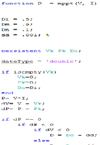
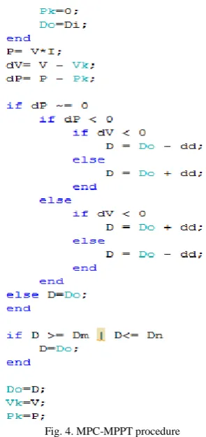
B. Model Predictive Control Procedure
Figure 3 shows the operating flowchart of P&O algorithm, Vpv and Ipv are output voltage and current of PV array and k is the value of variation in voltage to compute next perturbation. For a given perturbation on the voltage of the panel leads to an increase or decrease the output power of the PV, then the subsequent perturbation is generated in the same or opposite direction [1-2].
Fig. 4. MPC-MPPT procedure
As a consequence of the P&O algorithm, when the MPP is reached, the system may oscillate around it and this problem is overcome by reducing the perturbation step size. The discrete time set of equations of the flyback converter shown in Figure 2 is given by Equations 2 and 3 when switch is “ON” and Equations 4 and 5 when switch is “OFF” [1]:
ipv(k+1) =
𝑇𝑠
𝐿 Vpv(k) +ipv(k) (2)
Vc(k+1) = 1 −
𝑇𝑠
𝑅𝐶 Vc(k) (3)
ipv(k+1) = ipv(k) -
𝑇𝑠
𝐿𝑛 Vc(k) (4)
Vc(k+1) =
𝑇𝑠
𝑛𝐶 ipv(k) + 1 − 𝑇𝑠
𝑅𝐶 Vc(k) (5)
After determining the reference current, cost function can be obtained as in Equation 6 using the procedure shown in Figure 4.
𝑔𝑠=0,1= 𝑖𝑝𝑣𝑠=0,1(𝑘 + 1) − 𝑖𝑟𝑒𝑓 (6)
The objective of the paper is to minimize the cost function g. Using procedure illustrated in Figure 4 the final switching state for MPPT can be determined.
V. SIMULATION
ISSN (Print) : 2320 – 3765 ISSN (Online): 2278 – 8875
I
nternational
J
ournal of
A
dvanced
R
esearch in
E
lectrical,
E
lectronics and
I
nstrumentation
E
ngineering
(An ISO 3297: 2007 Certified Organization)
Vol. 5, Issue 1, January 2016
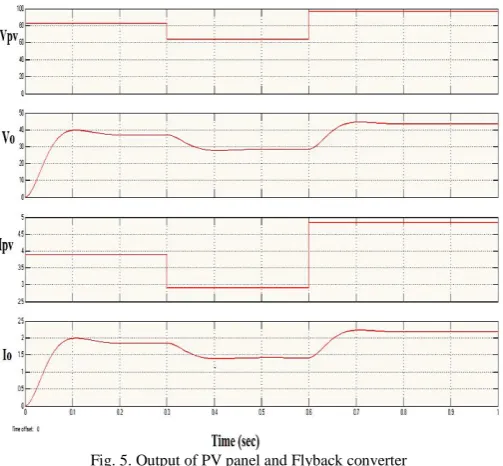
Then the value of voltage starts increasing linearly. This increase shows that the battery starts charging and it took 0.62 second.
Fig. 5. Output of PV panel and Flyback converter
Figure 5 shows the output voltage of PV (Vpv), flyback converter (Vo), output current of PV (Ipv) and flyback converter (Io) respectively. It is clear that oscillations in the outputs of flyback converter are low with MPC-P&O.
Fig. 6. Charging of Battery
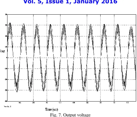
Fig. 7. Output voltage
Figure 7 and 8 shows the output voltage and current of the MPC-P&O with single phase full bridge inverter.
Fig. 8. Output current
VI. CONCLUSION
The model was simulated using SIMULINK and MATLAB. The study of a standalone solar PV energy system have been carried out using a flyback converter, battery and a single phase voltage source inverter. The P&O with model predictive controller performance has been investigated and it has given required response. The battery charging has been achieved through maximum power point tracking which gives sufficient backup. Thus it provided energy storage and can be applied to AC loads. So depending on the requirement one can choose it for low power application.
REFERENCES
[1] Mohammad Shadmand, Robert S. Balog and Haitham Abu Rub, “Maximum Power Point Tracking using Model Predictive Control of a
Flyback Converter for Photovoltaic Applications,” IEEE Renewable Energy & Advanced Power Electronics Research Laboratory, 2014.
[2] Neha Adhikari, Bhim Singh and A.L.Vyas, “Design and Control of Small Power Standalone Solar PV Energy System,” Asian Power
Electronics Journal, Vol. 6, No. 1, Oct. 2012.
[3] Sonali Surawdhaniwar and Ritesh Diwan, “An Improved Approach of Perturb and Observe Method Over Other Maximum Power Point
ISSN (Print) : 2320 – 3765 ISSN (Online): 2278 – 8875
I
nternational
J
ournal of
A
dvanced
R
esearch in
E
lectrical,
E
lectronics and
I
nstrumentation
E
ngineering
(An ISO 3297: 2007 Certified Organization)
Vol. 5, Issue 1, January 2016
[4] T. Esram and P. L. Chapman, "Comparison of Photovoltaic Array Maximum Power Point Tracking Techniques," IEEE Transactions on
Energy Conversion, vol. 22, pp. 439-449, June 2007.
[5] N. Patcharaprakiti, J. Thongpron, K. Kirtikara, D. Chenvidhya, and A. Sangswang, “Model Predictive Control Based on System
Identification of Photovoltaic Grid Connected Inverter,” International Journal of Information and Electronics Engineering, Vol. 2, No. 4, July 2012.
[6] Ahmed m. Atallah, Almoataz y. Abdelaziz, and Raihan s. Jumaah, “Implementation of Perturb And Observe MPPT of PV System with
Direct Control Method using Buck and Buck Boost Converters,” Emerging Trends In Electrical, Electronics & Instrumentation Engineering: An International Journal (EEIEJ), Vol. 1, No. 1, February 2014.
[7] D. Sera, T. Kerekes, R. Teodorescu, and F. Blaabjerg, "Improved MPPT Algorithms for Rapidly Changing Environmental Conditions," in
IEEE Power Electronics and Motion Control (EPE-PEMC), 2006, pp. 1614-1619.
[8] J. Ghazanfari and M. M. Farsangi, “Maximum Power Point Tracking using Sliding Mode Control for Photovoltaic Array,” Iranian Journal of
Electrical & Electronic Engineering, Vol. 9, No. 3, Sep. 2013.
[9] Mohammed A. Elgendy, Bashar Zahawi and David J. Atkinson, “Assessment of Perturb and Observe MPPT Algorithm Implementation
Techniques for PV Pumping Applications,” IEEE Transactions on Sustainable Energy, vol. 3, no. 1, January 2012.
[10] J. Surya Kumari, Dr. Ch. Sai Babu and A. Kamalakar Babu, “Design and Analysis of P&O and IP&O MPPT Techniques for Photovoltaic