C
o m p u t i n g
S
u r f a c e
The CS-2 Processor Module
i.
Safety Precautions . . . .
i
Federal Communications Commission (FCC) Notice . . . . i
General Precautions . . . ii
Lifting . . . ii
1.
Overview . . . .
1
2.
Module Packaging . . . .
3
Packing Dimensions . . . 3
Unpacking . . . 4
3.
Installing the Processor Module . . . .
7
Location . . . 7
Using the Meiko Beta Phase Controller . .
8
Power Supply . . . 8
Power Connections . . . 9
Fuses. . . 9
Operation . . . 10
i
Safety Precautions
i
Federal Communications Commission (FCC) Notice
Warning: Changes or modifications to this unit not expressly approved by the party responsible for compliance could void the user’s authority to op-erate the equipment.
NOTE: This equipment has been tested and found to comply with the limits for a Class A digital device, pursuant to Part 15 of the FCC Rules. These lim-its are designed to provide reasonable protection against harmful interfer-ence when the equipment is operated in a commercial environment. The equipment generates, uses, and can radiate radio frequency energy and, if not installed and used in accordance with the instruction manual, may cause harmful interference to radio communications. Operation of this equipment in a residential area is likely to cause harmful interference in which case the user will be required to correct the interference at his own expense.
iii When using the Genie fork lift you must first attach the two lift-clamp assemblies to either side of the module. Unscrew the securing screw that holds the telescopic section of the lift-clamp closed. Insert the rear locating pins into the holes at the rear edge of the module (the open end of the box section should face the front of the module). Align the front locating pins with the holes at the front of the mod-ule and tighten the holding screw.
Locate the forks of the Genie lift into the two box sections in the lift clamps. Raise the module by turning clockwise the handle on the Genie lift. Lower the module by turning the handle anti-clockwise.
Warning – Your attention is drawn to the operating instructions for the Ge-nie lift that ar e supplied by the lift’ s manufactur ers.
•
Genie fork lift, part number 73-FORK-GENIE.1
Overview
1
The Processor Module is a physical enclosure for up to 4 processor boards. Sup-porting infrastructure within the module consists of cooling fans, power supply, and connections to the CS-2 data network, the CS-2 control network, and exter-nal SCSI peripheral buses. Up to 4 SCSI disk devices may also be fitted within the module and connected to the processor boards in one of three standard con-figurations (all disks connected to one board, two disks to each of two boards, or one disk per board). An LED panel at the front of the module offers a 4x4 array of LEDs per board which are software controlled. The module is fully enclosed and FCC compliant.
3
Module Packaging
2
CS-2 modules are shipped in units of 1 to 4. The packaging consists of a wood base, packing foam, antistatic bag, and enclosing triple wall card outer.
Packing Dimensions
All dimensions are approximate.
Packing dimensions (single module):
Packing weight (without module):
Height 74 cm (29”)
Width 34 cm (13.5”)
Length 112 cm (44”)
4 module skid 20 Kg (44 lbs)
Module base 4.5 Kg (10 lbs)
Filler 1.8 Kg (4 lbs)
Outer card cover 4.5 Kg (10 lbs)
Packing foam 0.2 Kg (0.4 lbs)
Total (1 module) 11 Kg (24.4 lbs)
Module weight (without processor boards or peripherals):
Processor board weights (all processor options fitted):
Backplane boards:
Peripherals:
Unpacking
Warning – You are reminded of the safety precautions listed in General
Pre-cautions on page ii.
Modules are shipped in groups of 4 or 1.
For 4 module shipments each module is packaged individually and secured with the others onto a lar ge skid. To unpack a four module skid cut the outer banding and remove one module. Space the remaining three module packs uniformly over the skid.
Module weight 43.5 Kg (96 lbs)
MK401 (Dino) 2 Kg (4.4 lbs)
MK405 (Quatro) 3 Kg (6.6 lbs)
MK403 (VPU) 2.7 Kg (6.0 lbs)
MK515 Controller 0.15 Kg (0.33 lbs)
MK516 SCSI card 0.15 Kg (0.33 lbs)
MK511/2 Switch 0.15 Kg (0.33 lbs)
Disk carrier 0.6 Kg (1.3 lbs)
Disk device 0.8 Kg (1.8 lbs)
Module Packaging 5
2
•
To unpack each module first cut the banding and remove the outer card carton by lifting it clear of the module.•
Remove the protective foam from the top and front of the module.•
Remove the antistatic bag by pulling upwards.•
Lift the module from the packing base. Note: the module is heavy and must be lifted by at least two people or by using a Genie lift.•
Check the module for damage and advise the transportation company immediately if any is found.7
Installing the Processor Module
3
You must read this chapter thoroughly and completely before using your CS-2 module.
Location
The processor module must be located in a CS-2 Bay. This provides a firm level support for the module and has been designed to maximise the flow of cooling air through the module.
Warning – Overheating can damage this pr oduct. Do not block or cover any openings that ar e built into the module, and do not place the module near any sources of heat.
Modules sit on module trays that are fixed to the bay by telescopic rails. The tray must be extended from the bay before a module may be loaded onto it or removed from it.
Warning – Never extend mor e than one loaded module tray .
Operating Conditions
Module Dials
0 – 3 0 0 0 0 0 8 0 0 4 0 0 C
4 – 7 0 0 2 0 0 A 0 0 6 0 0 E
8 – 11 0 0 1 0 0 9 0 0 5 0 0 D
12 – 15 0 0 3 0 0 B 0 0 7 0 0 F
16 – 19 0 8 0 0 8 8 0 8 4 0 8 C
20 – 23 0 8 2 0 8 A 0 8 6 0 8 E
24 – 27 0 8 1 0 8 9 0 8 5 0 8 D
28 – 31 0 8 3 0 8 B 0 8 7 0 8 F
Recommended operating temperature 10–25oC (50–80oF)
Peak operating temperature 32oC (90oF)
Temperature gradient 10oC (18oF) per hour
Storage temperature -18–60oC (0–140oF)
ANSI media data integrity (max.) 32oC (89.6oF)
Relative humidity 20–80% non-condensing
Storage humidity 10–90% non-condensing
Altitude 3000 m (10 000 feet)
Installing the Processor Module 15
3
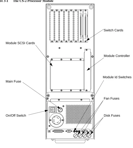
Figure 3-1 The CS-2 Processor Module
Module Controller
Fan Fuses
Disk Fuses Switch Cards
Main Fuse
Module SCSI Cards
On/Off Switch
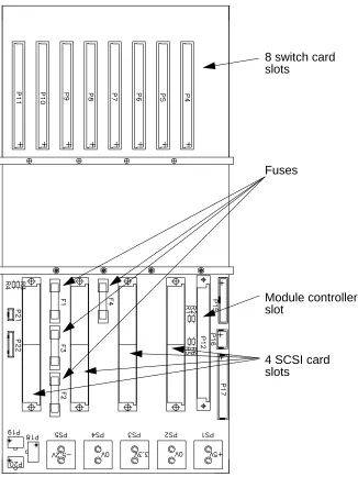
Figure 3-2 The MK510 Processor Module Backplane (not user serviceable)
Fuses
8 switch card slots
Module controller slot
17
Installing Processor Boards
4
Warning – The procedures in this chapter must only be undertaken by trained engineers.
Warning – You must disconnect the power supply befor e installing pr ocessor boards into the pr ocessor module.
Three types of processor board are available:
•
MK401 (single-SPARC with I/O), also known as Dino. This is a general purpose compute processor and operating system server.•
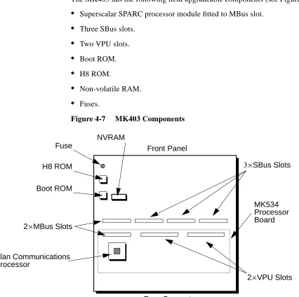
MK405 (quad-SPARC board), also known as Quatro. This is a high performance compute server.•
MK403 (single-SPARC, dual Fujitsu VPU), also known as VPU. This is a high performance vector processor.As newer higher performance SPARC modules become available, Meiko will of-fer these as field upgrade options. Simply unplug the old unit and replace with the new.
SBus Modules
Three SBus slots are provided and these may be fitted with standard SBus mod-ules. As with the processor modules SBus modules are simply plugged into the SBus connectors and secured with 2 screws. When using SBus cards that have external connections, for example a graphics card, remove the appropriate panel from the front of the MK401 — the panel is held in place by two small screws.
SBus devices are numbered from 0 to 2, device 0 being next to the processor slots. Device 4 is the board Ethernet and SCSI bus. Device 5 is the second on-board SCSI bus.
Memory
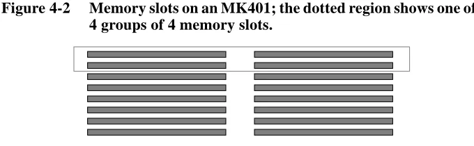
Up to 16 single in-line memory modules (SIMMs) may be fitted to the MK401 board (JEDEC 36 bit SIMMs). The array is constructed of 4 groups of 4 SIMMs, arranged as shown in Figure 4-2. Within each group the SIMMs must be identi-cal, but there is no requirement for the groups to be the same.
SIMMs can be either 4 Mbit DRAM or 16 Mbit DRAM technology, either single or double sided. This gives a minimum memory configuration of 16 Mbytes and a maximum of 512 Mbytes.
Front Panel Connections
Removable panels provide access to connectors on the optional SBus boards.
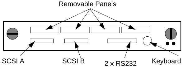
Figure 4-3 MK401 Front Panel Connections
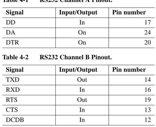
RS232 Connections
The two RS232 channels are connected as follows. Signal ground is pin 7, chas-sis ground in pin 1.
Table 4-1 RS232 Channel A Pinout.
Signal Input/Output Pin number
TXD Out 2
RXD In 3
RTS Out 4
CTS In 5
CSR In 6
DCD In 8
DB In 15
Ethernet
2× RS232
SCSI A SCSI B Keyboard SCSI Terminator Switch
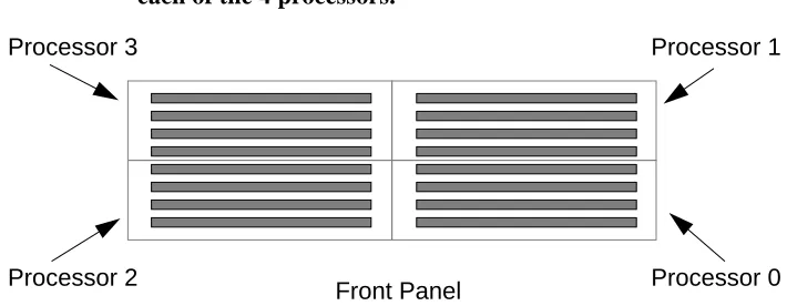
The processor slots are numbered from 0 to 3, from right to left (when viewed from the front) as shown in Figure 4-5.
Figure 4-5 MK405 Processor Numbering
Memory
Up to 16 single in-line memory modules (SIMMs) may be fitted to the MK405 board (JEDEC 36 bit SIMMs). The array is constructed of 4 groups of 4 SIMMs, one group for each processor — see Figure 4-6. Within each group the SIMMs must be identical but there is no requirement for the groups to be the same.
Figure 4-6 Memory slots on an MK405 showing the allocation of slots to each of the 4 processors.
SIMMs can be either 4 Mbit DRAM or 16 Mbit DRAM technology, either single or double sided. This gives a total minimum memory configuration of 64 Mbytes
Slot 0 Slot 1
Slot 2 Slot 3
Front
Processor 3
Processor 2
Processor 1
MK403 Vector Processor Board
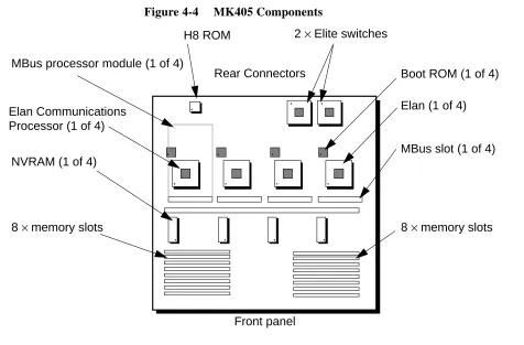
Field Upgradeable Components
The MK403 has the following field upgradeable components (see Figure 4-7):
•
Superscalar SPARC processor module fitted to MBus slot.•
Three SBus slots.•
Two VPU slots.•
Boot ROM.•
H8 ROM.•
Non-volatile RAM.•
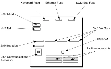
Fuses.Figure 4-7 MK403 Components
Fuse H8 ROM Boot ROM
NVRAM
2×MBus Slots
2×VPU Slots Elan Communications
Processor
Front Panel
3×SBus Slots
NVRAM
The non-volatile RAM holds system configuration information, environment variables, and the clock. It is held in a DIL socket and is easily replaced. Note however that the information within the NVRAM can only be restored by Meiko’s engineers.
The NVRAM contains lithium batteries which have special handling and dispos-al requirements — your attention is drawn to the precautions listed in the Generdispos-al Precautions on page ii.
Fuses
One fuse is used to protect the external keyboard/mouse. This fuse is 250 mA quick blow, Meiko part number 22–fu400–02e250.
External Connections
External connections are provided for a keyboard/mouse (8 pin circular socket), RS232 interfaces (2 channels provided by one 25-way D-type connector), and two independent SCSI buses (each via a 50-way connector). Note that the MK403 does not include SCSI controllers — the SCSI connectors must be con-nected to SCSI SBus cards.
Front Panel Connections
Removable panels provide access to connectors on the optional SBus boards.
Figure 4-8 MK403 Front Panel Connections
The green LED flashes at a slow steady rate (once per second) when operating normally. A quicker flash rate (2×normal) indicates that the SPARC processor is not responding; a very quick flash rate (3×normal) indicates that the H8 proces-sor on the module controller is not responding.
33
Installing Backplane Boards
5
Warning – The procedures in this chapter must only be undertaken by trained engineers.
Warning – You must disconnect the power supply befor e installing boards into the pr ocessor module.
A number of boards can be connected to the rear of the processor module. Along the top edge of the module backplane are connectors for up to 8 switch cards. Be-low these are another 5 slots; 4 are used for the module SCSI cards, and one (the larger one) for the module control card.
Blanking plates must be fitted over unused backplane slots to ensure correct cool-ing and compliance with RFI regulations.
Installation
The installation procedure for all backplane cards is similar. Note however that SCSI cards are normally installed during the module’s manufacture and are not readily removed.
Installing Backplane Boards 35
5
Figure 5-1 MK515 Components
Meiko may upgrade the H8 ROM from time to time.
The non-volatile RAM (NVRAM) holds system configuration information, such as the number of module switches. The NVRAM contains Lithium batteries which have special handling and disposal requirements — your attention is drawn to the General Precautions on page ii.
External Indicators
Two LEDs (one green, one amber) are visible from the rear of the module. The green LED is the module controller’s CAN heart beat, the amber light illuminates each time the controller writes to the CAN bus. These indicators are also dis-played in the top right hand corner of the module’s LED display.
Reset Switch
The reset switch is not accessible when the board is mounted in the module. It is used by Meiko engineers when bench testing the board.
H8 ROM
NVRAM Reset Switch
External power
RS232
Module Backplane Connector
External Connections
Two 3 pin connectors are provided for Meiko engineering use. They are used for bench testing of the board, and allow power and diagnostic RS232 connections to be made.
MK516 SCSI Cards
Transfers up to 5 SCSI buses from the processor module backplane to external connectors. Five ribbon cable connectors transfer the buses to disk devices mounted within the module, and one Beta Phase connector connects with exter-nally mounted devices.
Field Upgradeable Components
The MK516 has the following field upgradeable components:
•
Fuses•
Termination resistorsInstalling Backplane Boards 37
5
Figure 5-2 MK516 Components
Module Backplane Connector
Fuses
Bus 0
Bus 4
39
Installing SCSI Devices
6
Warning – The procedures in this chapter must only be undertaken by trained engineers.
The MK401 processor board is equipped with two independent SCSI-2 lers and includes 3 SBus slots that may be used to add additional SCSI control-lers. The MK403 Vector Processing board has no on-board SCSI controllers, but does have 3 SBus slots that can be used to add SCSI devices.
The CS-2 Processor Module includes space for up to 4 SCSI disk devices — these are connected to the SCSI controllers on the processor boards.
Additional SCSI disk devices or SCSI devices requiring frequent access (CD, tape, etc.) may be mounted externally to the processor module.
Module Disk Devices
The SCSI bus connection between the processor boards and the disk devices is via the Module SCSI Cards installed at the rear of the module. The Module SCSI cards take up to five1 independent SCSI buses from each processor board and transfer these to ribbon cable connections and a Beta Phase connector.
rib-Installing SCSI Devices 41
6
External Indicators
Three LEDs show from the front of the disk carrier. The green LED is the power light, the red LED is the activity light, and the yellow is the fail indicator. The activity signal is also displayed on the module’s LED panel using the small cir-cular red LED.
External SCSI Devices
External SCSI devices may be connected in two ways:
Front Panel Connections:
Some processor board types have SCSI bus connections on their front panels. When using these the cable should be routed behind the module’s front panel and into the cable guide below the module.
Module SCSI Card Connections: