Design of Miniaturized Rat-Race Couplers with Arbitrary Power
Division Ratios
Xiao Yang*, Zhen-Heng Liao, and Xu-Chun Zhang
Abstract—A miniaturized rat-race coupler with arbitrary power division ratio is proposed in this paper. The design formulas of the rat-race coupler with arbitrary power division ratio are derived using even-odd decomposition analysis. The proposed structure demonstrates miniaturized size and perfect isolation due to adding phase inverter to the branch. For demonstration, a 20 dB rat-race coupler operating at 1 GHz with 81.34% size reduction is designed and fabricated. There is good agreement between measured and simulated results.
1. INTRODUCTION
In modern communication systems, rat-race coupler is one of the most basic devices used for microwave and millimeter-wave applications. Different structures of arbitrary power division rat-race coupler have been reported widely. Rat-race couplers for arbitrary power division using 50 Ω lines only regardless of the power division ratio [1], using composite right/left-handed transmission lines [2–4] and usingπ-type stepped-impedance section [5] have been presented. The key of the large power division ratio is the realization of high-impedance line in the traditional structure [6].
A phase inverter (PI) is a device that changes the phase of a signal by 180◦ and is a crucial component in microwave circuits. It has been applied in many microwave components such as power divider [7], rat-race hybrids and feeding network of antenna arrays. In recent years, efforts have been directed to the development of novel phase inverters such as broad-band uniplanar phase inverter [8], dual-band phase inverter [9] and reconfigurable phase inverter [10]. The phase inverter is crucial components in microwave circuits for size reduction and perfect isolation.
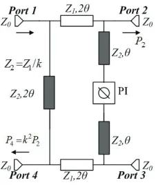
Figure 1. The proposed circuit model of the miniaturized rat-race coupler.
Received 8 November 2017, Accepted 26 February 2018, Scheduled 24 March 2018
* Corresponding author: Xiao Yang ([email protected]).
In this paper, a novel design of miniaturized rat-race couplers with arbitrary power division ratios is proposed, and the closed-form design formulas are presented. The arbitrary power division ratios are attained by controlling the characteristic impedance of the branch lines. Figure 1 shows the circuit model of the miniaturized rat-race coupler. The proposed structure has features of miniaturized layout and perfect isolation because of using a phase inverter. The rat-race coupler with transmission lines (Z1,Z2) and a phase inverter is designed. For verification, a 20 dB rat-race coupler operating at 1 GHz
with 81.34% size reduction is designed and fabricated.
2. DESIGN OF ARBITRARY POWER DIVISION RATIO RAT-RACE COUPLER
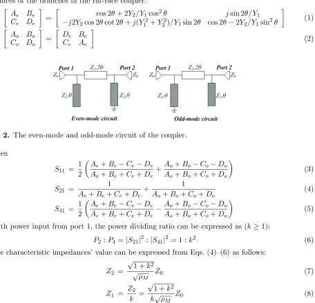
The closed-form design formulas of the rat-race coupler with the ideal phase inverter in Figure 1 can be derived using the even-odd-mode analysis. (Z0 is the impedance of port, and θ is the electrical
length of corresponding line at the central frequency fa). Figure 2 shows the even-odd-mode circuits (the PI in this structure cause the difference of line connected to the ground). The ABCD matrices of even- and odd-mode are Eqs. (1) and (2), respectively. Y1= 1/Z1 andY2= 1/Z2 are the characteristic
admittances of the branches in the rat-race coupler. Ae Be Ce De =
cos 2θ+ 2Y2/Y1cos2θ jsin 2θ/Y1
−j2Y2cos 2θcot 2θ+j(Y12+Y22)/Y1sin 2θ cos 2θ−2Y2/Y1sin2θ
(1) Ao Bo Co Do = De Be Ce Ae (2)
Figure 2. The even-mode and odd-mode circuit of the coupler.
Then
S11 =
1 2
Ae+Be−Ce−De Ae+Be+Ce+De +
Ao+Bo−Co−Do Ao+Bo+Co+Do
(3)
S21 =
1
Ae+Be+Ce+De +
1
Ao+Bo+Co+Do (4)
S41 =
1 2
Ae+Be−Ce−De Ae+Be+Ce+De −
Ao+Bo−Co−Do Ao+Bo+Co+Do
(5)
With power input from port 1, the power dividing ratio can be expressed as (k≥1):
P2 :P4 =|S21|2:|S41|2 = 1 :k2 (6)
The characteristic impedances’ value can be expressed from Eqs. (4)–(6) as follows:
Z2 =
√ 1 +k2
√ρM Z0 (7)
Z1 = Zk2 =
√ 1 +k2
k√ρM Z0 (8)
whereρM = (1 +S11)/(1−S11) (ρM ≥1) is the voltage standing wave ratio atfa.The power division
WhenρM = 1, the rat-race coupler is perfectly matched atfa, and this is the case of the traditional design method. Equations (7) and (8) are the same as the traditional one [5].
When ρM = 1, there are two different operation frequencies (f01 and f02, and f01 can be the
working frequency of the structure proposed by this paper). The lower and upper frequencies can be expressed as follows:
f01 =
2
π ·cot−1
1 +k2
2k
1− 1 ρM
·fa (9)
f02 = 2fa−f01 (10)
fa can be deduced from Equation (9) as follows:
fa= π
2f01/cot
−1
1 +k2
2k
1− 1 ρM
(11)
When k= 1, an equal division rat-race coupler can also be designed by Eqs. (7)–(10). The equal division design method [10] is the special case of the proposed one, and the proposed method is much simpler. Moreover, the proposed design method can be used in arbitrary division ratio design. The influences of Z1 and Z2 on the division ratio k are shown in Figure 3. The maximum power ratio is
20.5 dB (k= 10.6) whenZ1 = 160 Ω andZ2= 15 Ω, considering that 15 Ω–160 Ω is the range impedance
of microstrip line in reality.
0 20 40 60 80 100 120 140 160 0
5 10 10.6
Z1 ( )
k Z2=15 Z2=20 Z2=45 Z2=160 Ω Ω Ω Ω Ω
Figure 3. The influences ofZ1 and Z2 to the division ratiok.
For verification, using the analytical design method, when ρM = 10, Z0 = 50 Ω, for designing
a 20 dB (k = 10) rat-race coupler operating at f01 = 1 GHz. From Equations (7)–(10), the design
parameters can be calculated, and the values are Z1 = 15.89 Ω, Z2 = 158.9 Ω, fa = 3.5814 GHz and
f02= 6.16 GHz. The structure of the miniaturized rat-race coupler is shown in Figure 4.
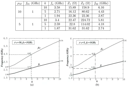
For further demonstration of the proposed analytical design method, the design parameters for different operations are listed in Table 1. Figure 5 shows the variation k according to Equations (10) and (11).
The structure of the phase inverter is shown in Figure 4(b), and the phase inverter can be simulated independently. The right line with defected ground structure is the phase inverter, and the left line is the reference line which is used to compare phase difference with the phase inverter. The phase inverter in this rat-race coupler consists of interdigital strip lines, five metallic via holes and defected ground structure. The 180◦ phase inverter is achieved by means of reversing electric field orientations with reference to the ground plane. The radial slot in the defected ground is the modified version of the conventionalλg/4 short-stub structure and has the advantage of wider bandwidth. The butterfly-shape defected ground structure is chosen because the rat-race coupler with a limited top layer structure. Ansoft HFSS13.0 is used to simulate the proposed phase inverter.
(a) (b)
Figure 4. The structure of the miniaturized rat-race coupler. (a) The dimensions of the rat-race coupler. (b) The configuration of the phase inverter.
Table 1. The design parameters of the rat-race couplers.
ρM f01(GHz) k fa (GHz) Z1 (Ω) Z2 (Ω) f02 (GHz)
10 1
10 3.58 15.89 158.9 6.16
5 2.71 16.12 80.62 4.43
1 1.94 22.36 22.36 2.87
5 1
10 3.4 22.47 224.72 5.81
5 2.59 22.8 114.02 4.18
1 1.87 31.62 31.62 2.74
(a) (b)
Figure 5. The variation of the power division ratio k. (a) ρM = 10, f01 = 1 GHz. (b) ρM = 5,
f01= 1 GHz.
3. EXPERIMENTAL RESULTS
For experimental demonstration, a substrate with dielectric constant 2.2, loss tangent δ = 0.0029, and thickness h = 0.8 mm is chosen. The fabricated board has an area of 52.29×53.38 mm2. The dimensions of the rat-race coupler are shown in Figure 4, and l1 and l2 are quarter wavelengths at fa,
respectively. The final dimensions areθ= 80◦,w0 = 2.46 mm,w1= 14 mm,w2= 0.2 mm,ws= 0.2 mm,
Figure 6. The simulated results of the phase inverter.
(a) (b)
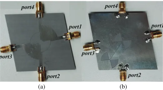
Figure 7. The picture of the miniaturized rat-race coupler. (a) Top layer. (b) Bottom layer.
is 0.3 mm. Ansoft HFSS13.0 is used to simulate the proposed rat-race coupler. The measurements are made by an AV3672 vector network analyser. Figure 7 shows pictures of the fabricated miniaturized rat-race coupler.
The measured results of the proposed rat-race coupler are shown in Figure 8 along with the simulated results (only show the necessary results at working frequency f01 = 1 GHz). As shown
in Figure 8(a), when the power input is from port 1, the measured return loss is better than 20 dB, the isolation better than 30 dB, and the power division ratio is 19.53 dB at the operation frequency 1 GHz, which is very close to the expected one.
As shown in Figure 8(b), when the power input is from port 3, the measured return loss is better than 20 dB, the isolation better than 30 dB, and the power division ratio is 19.42 dB at the operation frequency 1 GHz. As shown in Figure 8, the isolation is perfect owing to using the phase inverter. The measured results are in good agreement with the simulated ones.
(a) (b)
Figure 8. TheS-parameters of the coupler. (a) S11,S12, S13,S14. (b) S33,S32,S34, S24.
Figure 9. The phase difference of the coupler.
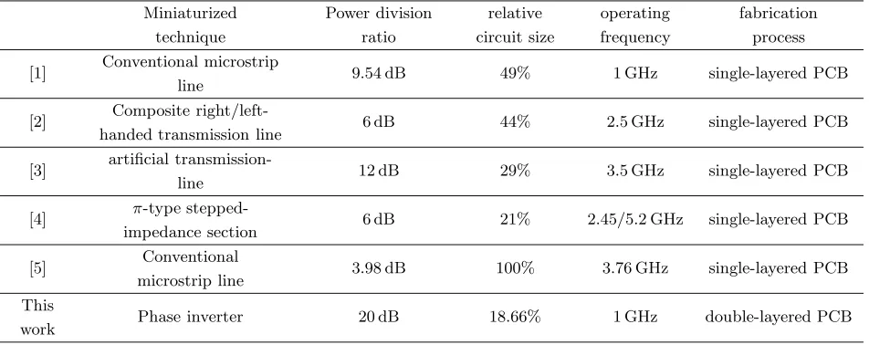
Table 2. Comparisons of published arbitrary power division rat-race couplers and this work.
Miniaturized technique
Power division ratio
relative circuit size
operating frequency
fabrication process
[1] Conventional microstrip
line 9.54 dB 49% 1 GHz single-layered PCB
[2] Composite
right/left-handed transmission line 6 dB 44% 2.5 GHz single-layered PCB
[3] artificial
transmission-line 12 dB 29% 3.5 GHz single-layered PCB
[4] π-type
stepped-impedance section 6 dB 21% 2.45/5.2 GHz single-layered PCB
[5] Conventional
microstrip line 3.98 dB 100% 3.76 GHz single-layered PCB This
4. CONCLUSION
A novel design of miniaturized rat-race coupler with arbitrary power division ratio has been proposed. A 20 dB race coupler with 81.34% size reduction is designed and fabricated. The structure of the rat-race coupler is miniaturized and simple. The realization of large power division ratio using microstrip line with high impedance has been solved easily. There is good agreement between the measured results and those of the theoretically designed, justifying the circuit configuration and the design theory.
REFERENCES
1. Park, M. J. and B. Lee, “Design of ring couplers for arbitrary power division with 50 Ω lines,”
IEEE Microw. Wireless Compon. Lett., Vol. 21, 185–187, 2011.
2. Chi, P. L., “Miniaturized ring coupler with arbitrary power divisions based on the composite right/left-handed transmission lines,” IEEE Microw. Wireless Compon. Lett., Vol. 22, 170–172, 2012.
3. Ho, K. L. and P.-L. Chi, “Miniaturized and large-division-ratio ring coupler using novel transmission-line elements,”IEEE Microw. Wireless Compon. Lett., Vol. 24, 35–37, 2014.
4. Xu, H.-X., G.-M. Wang, X. Chen, and T.-P. Li, “Broadband balun using fully artificial fractal-shaped composite right/left handed transmission line,”IEEE Microwave and Components Letters, Vol. 22, No. 1, 16–18, Jan. 2012.
5. Hsu, C. L., J. T. Kuo, and C. W. Chang, “Miniaturized dual-band hybrid couplers with arbitrary power division ratios,” IEEE Trans. Microw. Theory Tech., Vol. 57, 149–156, 2009.
6. Pon, C. Y., “Hybrid-ring directional coupler for arbitrary power divisions,”IEEE Trans. Microw. Theory Tech., Vol. 9, 529–535, 1961.
7. Zhang, X. C., T. Y. Wang, and Y. B. Xiang, “Wideband three-way out-of-phase microstrip power divider,” Electronics Letters, Vol. 51, 404–405, 2015.
8. Zhang, X. C., C. H. Liang, and J. W. Xie, “Microstrip phase inverter using interdigital strip lines and defected ground,”Progress In Electromagnetics Research Letters, Vol. 29, 167–173, 2012. 9. Liao, Z. H., X. C. Zhang, and T. Y. Wang, “A novel dual-frequency phase inverter,” IEEE
International Conference on Ubiquitous Wireless Broadband, 1–2, 2016.