Simulation Studies For Mmc–Hvdc Grid Using Ieee-39-Bus System
By Enhanced Dc Voltage Droop-Control With Active Filters
N Gangadhar
Associate Professor&H.O.D,Department Of Eee, Gates Institute Of Technology, Gooty, Ap, India
ABSTRACT: In this paper, the dc network dynamics of VSC-HVDC systems is investigated through enhanced dc voltage droop-control with active filters . The Filter analysis has been used to identify the factors that have an impact on the system stability. It has been determined that instability in the form of sustained oscillations can take place, and that the operating point, the dc side electrical characteristics, the strength of the ac system and the controller structure, are the major factors that impact the stability of the system. A frequency domain approach is proposed in this paper in order to explain the instability that occurs in the system. A two-terminal VSC-HVDC system is modelled as a SingleInput-Single-Output feedback system, and the VSC-system and the dc grid transfer functions are defined and derived. The proposed droopcontrol structure also autonomously imposes energy balance between the HVDC grid and its host ac system. Feasibility and performance of the proposed control method are evaluated based on time-domain simulation studies in the MATLAB platform, using the IEEE-39-Bus system that imbeds a five-terminal VSC– HVDC grid with filters. Each VSC station is a monopolar modular multilevel converter (MMC). The study results show that the proposed droopcontrol method enables the HVDC-AC system to reach a new steady state after transient events.
Index Terms: HVDC, VSC, Frequency Domain Analysis, Modular multilevel converter, dc voltage droopcontrol, dead-band droop-control, VSC–HVDC grid.
I. INTRODUCTION: In recent years, Voltage Source Converter based HVDC (VSC-HVDC) systems have been proposed as an attractive solution for the integration of renewable energy sources located far away from the consumption centres [1, 2] and for the integration of electricity markets located over large geographical areas [3, 4]. Since the first installation put in operation in 1997 [5] to interconnect the North and the South regions of Gotland, the VSC technology has improved tremendously in terms of power ratings, losses, and harmonic performance [16]. An example of that are the multilevel VSC topologies developed by the main manufacturers [10– 12], which have decreased the losses to a level comparable to thyristor-based HVDC systems (around 1% [10]). Moreover, compared to the thyristorbased converters, VSCs have very convenient controllability features, such as the independent control of active and reactive power. It is recognized also that VSC-HVDC systems are convenient
for the interconnection of weak grids. In addition, in the dc side, VSCs are so versatile that various strategies can be devised for the control of voltage-power in the dc side. Those features make VSC convenient for more complex HVDC structures, such as the multi-terminal HVDC (MTDC) systems proposed in [2–4, 6, 7]. From the dynamic performance perspective, VSC-HVDC systems have been traditionally viewed as means to enhance the dynamic performance of the existing ac system. For example, several works has been devoted to the use of VSC-HVDC systems for power oscillation damping, and for ac voltage support [43]. Another concern has been the undesired interactions between VSCs and the ac systems to which they are connected [44, 45]. However, few studies regarding the dynamic interaction between VSCs and the dc network can be found in the literature [47–49]. On the other hand, a large number of works can be found regarding the analysis of the dc network dynamics in low power multi-converter systems (dc microgrids) [36, 39, 41, 42]. For example, the impact of the load characteristics on the stability of the system is studied. For this kind of investigations, a frequency domain approach is proposed from which design criteria are provided. In high power applications, the interest in the dc network dynamics has arisen with the interest in MTDC system. In [10], a thorough analysis on the control and protection of MTDC systems has been carried out. In this work, instability in the dc side of the system was identified also in a point-to-point HVDC system. Other works, such as deal with the study of the stability of MTDC systems from a broad perspective. In these works, MTDC systems are modelled and the impact of the controller parameters on the stability of the system is determined through eigenvalue analysis. The risk of dc-side resonances is recognized in [7], where it is mentioned that the mitigation of low frequency dc-side resonances might become a complicated task in complex HVDC structures such as MTDC systems.
number of the operational converter stations, i.e., addition of a new station or out-of-service mode of a station, are accommodated based on the existing dead-bands. Subsequent to a transient event, the dead-band droop-control of the MMCs within a lower-priority group can be de-activated so that the MMCs can maintain their pre-disturbance operating points. Since the active power of a converter station intends to decrease due to the current limits, a single droop ratio based on reducing the active power is adequate for this approach.
II. VSC-HVDC OPERATION AND CONTROL :
The use of VSC in HVDC applications and the analysis of the behavior of the associated systems require an understanding of the fundamental properties and functionalities of the VSC technology. The intention of this chapter is to provide a basic but detailed background information on VSC-HVDC systems. The main structure and components of a VSC-HVDC system are initially described, followed by an introduction to the operational principles of a VSC. Thus, the interconnected layers of control that allow the VSC to operate as a controllable voltage source are presented. This will provide the basis for the understanding of the dynamic behavior of VSC-HVDC systems, as will be investigated in the following chapters. Finally, the control strategy of a typical two-terminal VSC-HVDC transmission link is presented and demonstrated via simulations.
Fig1: Outer-loop current controllers in d-axis of the dead-band droopcontrol: (a) DC-side voltage control, and (b) active power control.
The conventional dq-current control is the widely used approach for droop-based control of the DC-side voltage. Fig. 1(a) and(b) show the outer-loop d-axis controller that generates idref based on real power or DC-side voltage, respectively [9]. Fig. 2 shows the conventional power-voltage (P − Udc ) characteristics [9] that impose the
cooperation between the DCside voltage control of Fig. 1(a) and the active power control of Fig. 1(b). In Fig. 1, Pmax i(Pmin i) is the maximum (minimum) of real power of the corresponding converter where subscript i refers to the controller type, i.e., i = 1 is the DC-side voltage control and i = 2 is the active power control. idref max (idref min ) defines the top (bottom) straight-line characteristic of idref .Pref(Udcref) is the steady-state reference value of active power (DC-side voltage) and Pmea (Udcmea ) is the measured value. Kj and Tj are gains and time-constants of the PI controllers, where j = 1, 2, 3 and 4. The P − Udc characteristics of Fig. 2 show that Udc x of Fig. 1(b) can be Udc vm 1 or Udc vm 2 in Fig. 2. k in Fig. 1(b) refers to the slope of each segment of the P − Udc of Fig. 2 when the active power is within the range (Pmin 2 , Pmax 2 ).
Fig2: The test HVDC-AC hybrid system with filter
III.SIMULATION RESULTS: A. Test System
the HVDC grid and its parameters are given in [10] and Table I. The positive direction of power is assumed from the AC side to the DC side.
Performance Evaluation: The objective of this section is to evaluate the performance of the proposed enhanced droop-control during system transients. Initially, the system of Fig. 3 is under a steady-state condition as specified in Table I.
Case I - Removal of an MMC from service
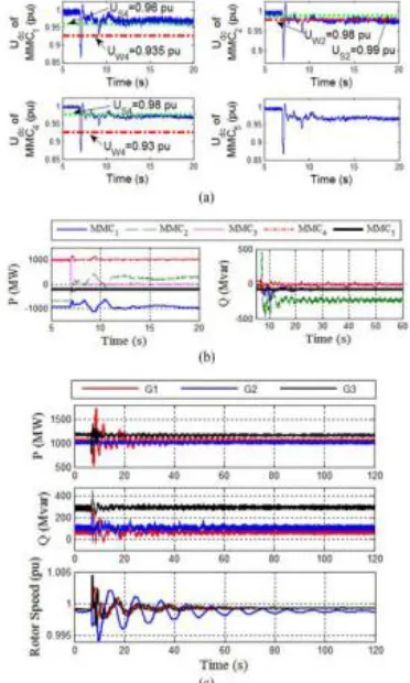
At time t = 7 s, the system is subjected to the removal of MMC3 (Group 1) from service, i.e., (i) the AC-side circuit breakers open and subsequently (ii) the DC-side is disconnected when the converter DC current reaches zero after about 10 ms. Fig. 3 shows the system response to the transients. Fig. 3(a) shows the DC voltages of the MMCs during the transient fault. Due to the disturbance at t = 7 s, all DC voltages drop from 1 pu to 0.869 pu which is smaller than the engage region thresholds, that is, UW 2 of MMC2 and UW 4 of MMC1 and MMC4 . So the droop-controls of the MMCs are activated and the DC voltages increase. Udc of MMC1 is higher than its disengage region threshold US4 at t = 7.23 s and Udc of MMC4 exceeds its US4 at t = 7.24 s. Then the DC voltages of MMC1 and MMC4 do not enter their engage regions again and the droopcontrols of the two MMCs are de-activated. Udc of MMC2 enters its engage region or disengage region several times between t = 7 s and t = 11.7 s. At t = 11.7 s,
Udc of MMC2 enters its engage region and after that it does not reaches its disengage region. Therefore, the new steady-state DC voltage of the HVDC grid is controlled by the droop-control of MMC2 . Udc of MMC5 is always higher than UL8 = 0.7 pu, under which the Group 4 voltage margin is formed in Table II, and MMC5 is under normal operation. Fig. 7(a) indicates that the removal of MMC3 from service does not result in the DC voltage collapse of the system, even in the absence of the DC slack bus, i.e., MMC3 , when the proposed droop-control is utilized.
Fig3 : System response to the removal of MMC3 : (a) DC voltages of MMCs, (b) power of MMCs, and (c) power and rotor speeds of generators.
Case II - DC transmission line trip-out
to decrease while Udc of the other MMCs intend to increase. The DC voltage of MMC1 remains higher than its disengage region threshold US4 and the droopcontrol of MMC1 is de-activated during the transient process. Udc of MMC2 becomes smaller than UW 2 at t = 7 s and enters its engage region. But 0.24 s later, Udc of MMC2 increases and becomes higher than US2 , which is the threshold of the disengage region of MMC2 . Between t = 7 s and t = 8.68 s, the DC voltage of MMC2 repeatedly operates at either the engage region or the disengage region. After t = 8.68 s, Udc of MMC2 operates at its disengage region or the dead-band. Therefore, the droop-control of MMC2 is de-activated after t = 8.68 s. Udc of MMC4 increases and enters the engage region (Udc > UW 3 ) of MMC4 at t = 7 s. However 0.27 s later the DC voltage of MMC4 becomes lower than US3 (the disengage region threshold) and the corresponding droop-control is de-activated. As the DC slack bus, MMC3 tries to prevent the rising DC voltage from 1.034 to 1 pu after the fault. However, MMC5 does not participate in regulating the DC voltage of the HVDC grid. In this transient process, the droop-controls of MMC2 and MMC4 are activated and assist MMC3 to stabilize the DC voltage of the HVDC grid. At the new steady-state, MMC2 and MMC4 de-activate their droop-controls and the DC voltage is regulated by MMC3 .
Fig4: System response to the outage of DC transmission line: (a) DC voltages of MMCs, (b) power of MMCs, and (c) power and rotor speeds of generators.
IV.CONCLUSION: In this paper , the dc-network of VSC-HVDC systems were thoroughly investigated in two-terminal connections and new perspectives were introduced to the control of VSC-MTDC grids. As an introductory part, Chapter 3 set the background for poorly-damped conditions in dynamic systems. It was shown in an explicit way that a VSC station operating as a constantpower provider in a VSC-HVDC or in motor drives, introduces the effect of a negative resistance. This has a degrading effect on the damping of the complex poles of the system, whose frequency is usually related to the characteristic frequency of the LC filter between the VSC and its dc source in drive applications, or the dc-transmission link natural frequency in a twoterminal VSC-HVDC connection.
This paper also presents a method to determine the deadbands to alleviate the impact of transient events on the operating points of converter stations with filters. The salient feature of the proposed droop-control method is that it does not require retuning the voltage margins and dead-bands as the number of HVDC stations, due to the in- or out-of-service modes of converters, changes. A set of time-domain simulation studies, using the matlab software tool, were conducted on a five-terminal VSC-HVDC grid to demonstrate the feasibility and effectiveness of the proposed control method for the HVDC grid applications.
REFERENCES :
[1] N. Flourentzou, V. G. Agelidis, and G. D. Demetriades, “VSC-based HVDC power transmission systems: An overview,” IEEE Trans. Power Electron., vol. 24, no. 3, pp. 592–602, May 2009.
[2] W. Lu and B. T. Ooi, “DC overvoltage control during loss of converter in multi-terminal voltage-source converter-based HVDC (M-VSC-HVDC),” IEEE Trans. Power Del., vol. 18, no. 3, pp. 915–920, Jul. 2003.
[3] O. Gomis-Bellmunt, J. Liang, J. Ekanayake, and N. Jenkins, “Voltagecurrent characteristics of multi-terminal HVDC-VSC for offshore wind farms,” Elect. Power Syst. Res., vol. 81, no. 2, pp. 440–450, Feb. 2011.
[4] M. Saeedifard and R. Iravani, “Dynamic performance of a modular multilevel back-to-back HVDC system,” IEEE Trans. Power Del., vol. 25, no. 4, pp. 2903–2912, Oct. 2010.
Int. J. Elect. Power Energy Syst., vol. 56, pp. 198–208, Mar. 2014.
[7] D. V. Hertem and M. Ghandhari, “Multi-terminal VSC-HVDC for the European supergrid: Obstacles,” Renew. Sustain. Energy Rev., vol. 14, no. 9, pp. 3156–3163, Dec. 2010.
[8] J. Cao and J. Y. Cai, “HVDC in China,” presented at the EPRI, HVDC & FACTS Conf., Palo Alto, CA., USA, Aug. 2013.
[9] T. K. Vrana et al., “A classification of DC node voltage control methods for HVDC grids,” Elect. Power Syst. Res., vol. 103, pp. 137–144, Oct. 2013.
[10] F. B. Ajaei and R. Iravani, “Dynamic interactions of the MMC-HVDC grid and its host AC system due to AC-side disturbance,” IEEE Trans. Power Del., vol. 31, no. 3, pp. 1289–1298, Jun. 2016.
[11] E. Prieto-Araujo, F. D. Bianchi, A. Junyent-Ferre, and O. Gomis-Bellmunt, “Methodology for droop control dynamic analysis of multi-terminal VSCHVDC grids for offshore wind farms,” IEEE Trans. Power Del., vol. 26, no. 4, pp. 2476–2485, Oct. 2011.
[12] R. T. Pinto et al., “A novel distributed direct-voltage control strategy for grid integration of offshore wind energy systems through MTDC network,” IEEE Trans. Ind. Electron., vol. 60, no. 6, pp. 2429–2441, Jun. 2013. [13] J. Beerten and R. Belmans, “VSC-MTDC systems with a distributed DC voltage control—A power flow approach,” in Proc. IEEE PowerTech, Trondheim, Norway, Jun. 2011, pp. 1–6.