University of Windsor University of Windsor
Scholarship at UWindsor
Scholarship at UWindsor
Electronic Theses and Dissertations Theses, Dissertations, and Major Papers
2013
Adapting Ad Hoc on Demand Vector Routing (AODV) for Static
Adapting Ad Hoc on Demand Vector Routing (AODV) for Static
Sensor Networks, Including a Test-bed Design
Sensor Networks, Including a Test-bed Design
Ahmad El Baba
University of Windsor
Follow this and additional works at: https://scholar.uwindsor.ca/etd
Recommended Citation Recommended Citation
Baba, Ahmad El, "Adapting Ad Hoc on Demand Vector Routing (AODV) for Static Sensor Networks, Including a Test-bed Design" (2013). Electronic Theses and Dissertations. 4753.
https://scholar.uwindsor.ca/etd/4753
This online database contains the full-text of PhD dissertations and Masters’ theses of University of Windsor students from 1954 forward. These documents are made available for personal study and research purposes only, in accordance with the Canadian Copyright Act and the Creative Commons license—CC BY-NC-ND (Attribution, Non-Commercial, No Derivative Works). Under this license, works must always be attributed to the copyright holder (original author), cannot be used for any commercial purposes, and may not be altered. Any other use would require the permission of the copyright holder. Students may inquire about withdrawing their dissertation and/or thesis from this database. For additional inquiries, please contact the repository administrator via email
Adapting Ad Hoc on Demand Vector Routing (AODV) for Static Sensor Networks,
Including a Test-bed Design
By
Ahmed El Baba
A Thesis
Submitted to the Faculty of Graduate Studies
through the Department of Electrical and Computer Engineering in Partial Fulfillment of the Requirements for
the Degree of Master of Applied Science at the University of Windsor
Windsor, Ontario, Canada 2012
Adapting Ad Hoc on Demand Vector Routing (AODV) for Static Sensor
Networks, Including a Test-bed Design
By
Ahmed El Baba
APPROVED BY:
____________________________________________
Dr. Mohammed Khaled
Department of Electrical and Computer Engineering
______________________________________________
Dr. Alioune Ngom
Department of Computer Science
______________________________________________
Dr. Kemal Tepe, Advisor
Department of Electrical and Computer Engineering
______________________________________________
Dr. Mitra Mirhassani
Department of Electrical and Computer Engineering
iv | P a g e
Declaration of Originality
I hereby certify that I am the sole author of this thesis and that no part of this
thesis has been published or submitted for publication. I certify that, to the best of my
knowledge, my thesis does not infringe upon anyone's copyright, nor violate any
proprietary rights; any ideas, techniques, quotations, or any other material from the work
of other people included in my thesis, published or otherwise, are fully acknowledged in
accordance with the standard referencing practices. Furthermore, to the extent that I have
included copyrighted material that surpasses the bounds of fair dealing within the
meaning of the Canada Copyright Act, I certify that I have obtained a written permission
from the copyright owner(s) to include such material(s) in my thesis and have included
copies of such copyright clearances to my appendix.
I declare that this is a true copy of my thesis, including any final revisions, as
approved by my thesis committee and the Graduate Studies office, and that this thesis has
v | P a g e
Abstract
Wireless sensor networks (WSNs) are deployed for their diverse ability to
monitor and control equipment ranging from transmission line systems to hydro usage
data in residential areas. Specifically, Mesh networks are valuable in smart grid
applications due to their self-configuring, self-healing properties. This project modified
Ad Hoc On-Demand Distance Vector routing Uppsala University (AODV-UU) to
achieve two key functions; design a protocol that monitors static sensor networks for the
collection of different data, and to establish then maintain a route to a specified control
center. This is achieved by tuning the maintenance periods of the protocol and creating a
mechanism for sharing the control center address. After a node receives the new control
center address, it will promptly establish a route and keep it up. Secondly, a test-bed was
designed to facilitate the setup of networks to simulate sensor networks, and to further
assist in data harvesting of critical test data from all nodes concerned with the tests to be
vi | P a g e
Acknowledgements
I would like to begin by thanking Dr. Kemal Tepe for not only advising me during
this thesis, but for pushing me beyond my expectations and personal goals. It was an
absolute pleasure and privilege to be given this opportunity. I would also like to thank my
colleague, friend, and lab partner Shawn Ruppert for accompanying me in this journey,
both the hard times and the joyous ones. I would also like to extend my gratitude to all of
my colleagues at the WiCIP lab, including but not limited to Dr. Nabih Jaber for his
support and guidance, Bill Cassidy, Syed Sami, Kazi Atiqur Rahman, Khaja Mohammad
Shazzad, Izhar Ahmed, Dr. B. K. Singh, M. J. Toimoor, Sarab Al Rubeaai, Patrick Casey,
and everyone else who helped enhance my experience in the lab. But ultimately, a big
thank you goes out to my family who have always provided nothing but positive support
throughout my academic career.
Sincerest Thank You,
vii | P a g e
Table of Contents
Declaration of Originality ... iv
Abstract ...v
Acknowledgements ... vi
List of Tables ... ix
List of Figures ...x
Abbreviations ... xi
Chapter 1 - Introduction ...1
1.1 Motivation ...1
1.2 Problem Statement ...2
1.3 Thesis Contribution ...3
1.4 Background ...3
1.5 Thesis Organization ...6
Chapter 2 - RELATED WORK ...8
2.1 Types of faults and their effects ...8
2.2 Related work ...10
2.3 AODV and Latency ...13
2.4 AODV and Throughput ...14
2.5 Wireless Links Utilized for AODV ...16
2.6 Summary ...17
Chapter 3 - AODV Overview and Test-Bed ...18
3.1 AODV General Functionality and Example Scenario ...18
3.2 Important Parameters in AODV ...21
viii | P a g e
3.4 Summary ...24
Chapter 4 - AODV-Modified for Semi-Static nodes with Test-bed ...26
4.1 Overall Proposed Modifications to AODV ...26
4.2 Hardware and Software ...27
4.3 System Requirements and the Shortfalls of Unmodified AODV ...30
4.4 Control Center Graphical User Interface ...32
4.5 AODV Protocol Modifications ...36
4.6 Results of Modified AODV vs Unmodified AODV ...47
Chapter 5 - Conclusion and Future Work ...53
5.1 Conclusion ...53
5.2 Future Work ...54
References / Bibliography...56
ix | P a g e
List of Tables
2.3 End to End Latency Unmodified AODV ... 13
4.3 Dropped Packets For Unmodified AODV in multi-hop ... 31
4.5 Summary of methods for Keeping a Route Alive ... 40
4.6.1 Throughput Comparison between Unmodified and Modified AODV ... 49
x | P a g e
List of Figures
Hydro One Smart Meter ... 4
Wireless Sensors in a City Grid ... 6
Before GPS routing, RREQ [18] ... 12
After GPS routing, RREQ [18] ... 12
AODV-SGR Improved Throughput over AODV-UU ... 15
AODV-SGR Improved Throughput over AODV ... 15
Explaining AODV, scenario ... 19
Burst vs Regular "Hello" Mechanism, AODV-UU ... 22
System overview, sensors on transmission line ... 26
Project test-bed (Hardware) ... 28
Unmodified AODV route build time ... 30
Developing the test-bed in Netbeans IDE ... 33
Test-bed GUI -clean ... 34
- Test Bed Data Script Sharing Flowchart ... 35
RCC packet structure ... 37
Burst Mechanism flowchart ... 38
Sensor nodes with paths to control center... 39
xi | P a g e
Abbreviations
AC Alternating Current
AMI Advanced Metering Infrastructure
AMR Automated Meter Reading
AODV Ad-Hoc On Demand Vector Routing
AODV-UU Ad-Hoc On Demand Vector Routing Uppsala University
CC Control Center
DC Direct Current
DG Distribution Grid
GW-h Giga Watt Hours
―Hello‖ Neighbor polling message, utilized by AODV
IEEE Institute of Electrical and Electronics Engineers
IP Internet Protocol
LAN Local Area Network
MAC Media Access Control (MAC address)
xii | P a g e
RCC Route Control Center
RREP Route Reply
RREQ Route Request
RRER Route Error
SGR Smart Grid Routing
Wi-Fi Synonym for WLAN
WLAN Wireless-LAN
1 | P a g e
Chapter 1 - Introduction
1.1 Motivation
Electricity has become a prime resource that controls every aspect of daily life.
For this reason, different power transmitters have been developed in order to improve the
distribution of electricity to meet the demands of the growing technologically dependent
population. The first electrical grid developed in 1882 was a DC grid which transmitted
DC power. In 1886, a shift from DC grids was observed to AC, which allowed an
increased in range of power transition across numerous cities and countries with better
efficiency. Following the move to AC, the principle design of this grid is reliable and
rarely changed, with millions of people across the globe relying on its operation to this
day.
The grid was originally designed with a single purpose in mind, which was to
carry power from various power sources (hydro or coal plant) to consumers. The initial
grids successfully carried DC power, but because of its low efficiency in transmission
over longer distances, power generators needed to be situated relatively close to
consumer households and institutions. Therefore, it was best to spread many small
generators around each city wherever there was a substantial demand for electricity. In
October of 1888, the first AC generator was then patented due to Nikola Tesla's efforts,
which introduced longer range power delivery [1]. The AC current's characteristics allow
longer transmission of power, with higher efficiency than its DC counterpart. Therefore
AC transmission marked the beginning of the distribution that is implemented today.
The first demonstration of electrical power transmission was in 1891 at Frankfurt.
A 25kV transmission line was used to prove the viability of AC in long distance
transmission, over a distance of 175 km from Lauffen on the Neckar to Frankfurt [2]. The
demand for electrical power ever since sharply increased to the level of high demands
2 | P a g e
By the 20th century, a substantial number of the world's countries relied on
electrical output where even residential households are into the grid. This includes
everyday appliances which require electrical power that is produced by hydro or coal
plant hundreds of miles away from the site of use. Generally, voltage in households can
range between 110v and 220v around the world. Drawing back from the kV that was
discussed earlier, this indicates that the voltage is stepped down between the actual grid
and the outlets found in our houses. This is done through local sub-stations and again
through step-down transformers. This process is required to transmit power efficiently at
higher voltages, but to be output at manageable voltages.
In Ontario alone, demographically speaking, the population has steadily risen
through the years. With that growing population, the grid also expanded accordingly to
meet the electrical needs observed. As of 2009, 124,684.6 GW-h [3] of total electrical
power has been used by the population of Ontario. This indicates that the demand for
power is staggering in not only Ontario, but also in numerous countries and cities around
the world. Fortunately the power delivery systems have improved in the form of AC grids
which carry electrical power over longer distances. Unfortunately this power grid, despite
its advantages, remains very similar to the designs first introduced in the early 1900s. The
control systems at the ends of the grid have evolved; but there remains a deficit of
valuable sensors that could relay information concerning the state and events of the
power lines themselves, and what is happening to the power delivered.
1.2 Problem Statement
This project has two main objectives:
First to choose, modify, and present a working communication prototype which can be
used for smart grid systems the prototype should be able to create routes between
3 | P a g e
Secondly to test-bed development that will aid in the setup and data harvesting of test
data from multiple sensing nodes.
1.3 Thesis Contribution
The research and documentation of the new communication protocol will be used
to implement a java test-bed to aid future researchers. The test-bed will build of off
lessons learned from the pursuit of the new communication protocol for Smart Grid. The
test-bed should be able to take care of the tedious checks to the wireless network as well
as document and collect various statistics from all nodes that are part of the test. Since the
testing will be carried out under real world conditions, with various real world
interference. The wireless network will be compromised of Adhoc test-bed connections,
following the IEEE 802.11(A,B,G,N) protocols. The nodes will also be running Linux
kernel 2.6.x.
1.4 Background
Maintenance mechanisms as proposed by the RFC3561 [4] to keep routes alive.
Unfortunately, frequent packet transmission congests the channel, keeping it very busy. It
is crucial to understand which of the protocol parameters can be tuned and modified once
4 | P a g e
1.4.1 Smart Meters
Fig 1 Hydro One Smart Meter – [http://www.hydroone.com/SiteCollectionImages/hero/smart_meter_01.jpg]
In this day and age, technology has permitted humans to communicate
information regardless of distance. Unfortunately power companies still require manual
collection of power usage from residential houses and businesses. Smart meters would
allow easy and accurate reporting of power usage, making running generators more
efficient due to near real time communication of power consumption instead of running
the generators based on statistics. Smart meters would bring about various benefits such
as making consumer power usage more easily monitored by the supplier, thereby
allowing electrical power providers to accommodate electrical supply demands. Also, it
cuts down on periodic trips to consumer locations for data collection. Smart meters have
recently been introduced and implemented in Ontario [10] with the hope of building more
efficient, environmentally sound electrical systems.
1.4.2 Communication System and Test-bed
For communication purposes, WLAN will be utilized. WLAN also known as
WI-FI, was initially introduced in 1992 [12] but did not gain worldwide attention until 1999,
5 | P a g e
protocol with various sub protocols (a/b/g/n) that has become famous worldwide [13].
The 802.11 protocol was chosen for testing due to its wide availability, with millions of
devices depending on it world-wide.
For testing purposes, the network needs to be set-up manually before testing.
After various manual setups, smaller inconsistencies began to emerge due to human
errors. Therefore, the best course of action was to pursue an automated bed. The
test-bed was developed using Java which created simple network topologies using MAC-kill
commands in the Linux kernel, as well as data retrieval after tests were done. This
eliminated the tedious job of manual setup of routing rules, tests, and then retrieval of
data from nodes.
1.4.3 Smart Grid Scenarios for AODV
The smart grid can be split into two generic parts, the first part concerns the smart
meters that will be used at all consumer locations, and the second part concerns the
actual sensors on the transmission lines and various substations that will be relaying
information back to the control center.
The smart meter consumer reports can be collected periodically or on demand by
the control center, or a drive by utility vehicle. Earlier ways of collecting and billing
customers would require periodic physical visits to each customers location and reading
the power meter, where charging was done statistically per location, and the difference
would either be charged or credited back to the customer. With the deployment of smart
meters, the utility companies will have a more accurate snapshot of the grid (Figure. 2)
and its usage at any given time, while the customers get billed much more accurately
6 | P a g e
Fig 2 Wireless Sensors in a City Grid [http://images.fastcompany.com/upload/smart-grid-city.jpg]
Smart grids streamline and optimize transmission line monitoring. Intelligent
sensors can process real-time voltage and current information of the lines to try and
predict upcoming faults or irregularities in the line or supply. This is significant for
keeping the power generation running at the highest efficiency levels. Also faults that
were discussed earlier in Section 2.1 can be detected immediately and relayed back with
accurate location to utility control centers cutting down repair time, especially with
underground power lines like the ones found in bigger cities.
1.5 Thesis Organization
The rest of this thesis is structured in the following format: Chapter 2 will discuss
related work concerning different approaches to smart grid protocols and modifications
of AODV to improve robustness. Chapter 3 will analyze current AODV and some of the
7 | P a g e
functionality of the test-bed. Chapter 5 will discuss the final modified AODV and its
8 | P a g e
Chapter 2 - RELATED WORK
A staple in all research to be conducted properly is that one must revisit earlier
work pertaining to the same area. For this chapter the features that are required for an
ideal smart grid and how AODV can be modified to reach those goals will be discussed.
Section 2.1 will discuss the different faults that could occur on power lines. Section 2.2
discusses routing protocols designed for smart grids including their advantages and
disadvantages. Section 2.2 explores AODV and how its mechanism affects latency.
Section 2.3 focuses on the throughput of AODV and how it can be improved. Section 2.4
briefly touches on wireless communication that can be used, mainly IEEE 802.11 WLAN
and IEEE 802.15.4 Zigbee. Section 2.5 will provide a summary of the discussed work.
2.1 Types of faults and their effects
On the distribution grid, many faults can occur on the three phase lines, but they
can always be classified into one of four fault types. They can be either transient,
persistent, symmetric, or asymmetric faults. The following sub-sections will discuss these
further.
2.1.1 Transient Fault
A transient fault is a fault that has already occurred, and no longer is present.
This could be caused by a lightning strike, animal contact, or a tree falling down and
momentarily grounding one of the lines. A single line-to-ground fault is one of the most
common faults to occur in overhead transmission lines, making up 70% of total faults
that occur [5, 6]. These types of faults can cause a current spike in the grounded lines,
which consequently affect the voltage on the damaged transmission line, as well as
9 | P a g e
another type of protection circuit to keep the rest of the grid online. These types of faults
are more common to overhead power lines than underground, as underground lines tend
to be more persistent [7].
2.1.2 Persistent Fault
A persistent fault is a fault that occurs and keeps occurring unless fixed. A
persistent fault is classified as a fault that does not disappear when the power is
disconnected. The most common cause for this type of fault is mechanical damage to the
transmission cable.
2.1.3 Symmetric Fault
A symmetric in the fault (or more commonly known as a balanced fault), affects
all three phases equally. This type of fault is much less common, but documented
regardless. Since they are less common to occur but easier to understand they are mostly
used in simulations to come up with better plans of action to deal with the more common
asymmetric symmetric fault.
2.1.4 Asymmetric Fault
An asymmetric symmetric fault is more common than symmetric faults which are
faults that affect the phases individually. Asymmetric faults can be caused by line-to-line
shorts, line-to-grounds, or double line-to-ground faults.
Line-to-line: Also phase-to-phase is a short between two different phases, they are
caused by the ionization of the air surrounding them or the weather of the
insulation surface around the lines themselves.
Line-to-ground: These faults are classified by a phase line shorting to the ground
wire. These types of shorts affect the current on all three phases which
10 | P a g e
Double line-to-ground: Like the line to ground, in this scenario two phase lines
are grounded. This fault is mostly caused by storm damage.
2.1.5 Locating Faults
One of the most requested features from a smart grid system is predicting faults
due to voltage or current irregularities and locating and carrying out proper maintenance
actions. The current options used by power companies to locate faults include using a
time-domain reflector [7] or ―thumper’ tests for areas that have reported faults, but
continues to work [8]. The smart- grid would offer accurate and faster reports regarding
faults that fit different characteristics due to their permanent link to the control centers.
2.2 Related work
Ad hoc On-Demand Distance Vector (AODV) Routing is a routing protocol
for mobile ad hoc networks (MANETs) and other wireless ad-hoc networks. It is jointly
developed in Nokia Research Center, University of California, Santa
Barbara and University of Cincinnati by C. Perkins, E. Belding-Royer and S. Das.[4]
Since, AODV is optimized for mobile nodes, the protocol brings many advantages and
some disadvantages, with regards to our purposes. AODV utilizes a set of frequent
2.2.1 DSR – Dynamic Source Routing
AODV is an on demand protocol; therefore routes are only created when required.
The information of the network topology is not saved anywhere; therefore AODV
actively creates routes through the cooperation of all nodes involved.
DSR is a routing protocol which uses predefined routing tables saved on each
11 | P a g e
DSR will check its routing table for a route if it already exists. This presents a critical
difference in operation, as AODV requires maintenance packets to keep neighbors and
create routes, DSR on the other hand will immediately know whether it has a route to the
required destination or not. For DSR, in the case that the destination is not available, the
protocol will deploy a RREQ to seek out a route to the destination [RFC4728].
DSR’s mechanism for handling routes presents it with faster route setup,
assuming the route exists in the memory cache of every node in the system, but can cause
long route setup times when seeking an unknown route. When DSR was compared with
AODV with different node counts [14], and traffic density, AODV performed better with
regards to packets dropped and energy consumption.
2.2.2 QOS – Routing
A recurring feature of smart grid communication is QOS (Quality of Service)
routing [15, 16, and 17]. QOS in networking allows the delivery of data packets with
special requirements. With technologies advancing, options to check and filter packets
permits higher quality of data with less errors to be relayed. The QOS can be affected by,
throughput, dropped packets, errors within packets, or out-of-order delivery. These
parameters are crucial and require monitoring for sensitive applications.
Guaranteeing the QOS within a routing protocol is essential for smart grid
communication due to the importance of the data being dealt with. QOS features were
added to Zigbee, and IEEE 802.15.1Bluetooth to increase their throughput and decrease
delay when transmitting and receiving messages destined for smart grid purposes [15].
2.2.3 Geo-Based Routing
AODV routing, as previously discussed, creates routes with no predetermined
knowledge of the route and its precursors. Adding a geographical parameter to the
routing can minimize traffic in unrelated areas, thus exponentially decreasing the traffic
12 | P a g e
to its destination. Through a simulation by Rowan University [18], the RREQs were
substantially limited to the area of the possible destination. In Figure 3, Node 2 and Node
3 are outside the general routing area of the source.
Fig 3 Before GPS routing, RREQ [18]
Fig 4 After GPS routing, RREQ [18]
Using the fresh GPS coordinates of the nodes, the source can limit its RREQ
broadcast region to exclude Node N2 and Node N3, Figure 4. This approach significantly
decreased the amount of RREQ’s, in turn lowering network traffic during the route
13 | P a g e
2.3 AODV and Latency
The latency we will be measuring and drawing from is two-way latency, or the
time it takes a packet to traverse the network from the source to destination and back.
This latency is important to note, as it clearly is affected by the number of nodes.
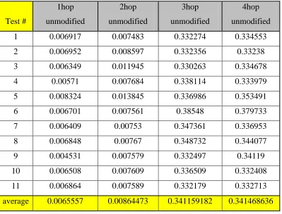
Table 1 2.3 End to End Latency Unmodified AODV
Test #
1hop
unmodified
2hop
unmodified
3hop
unmodified
4hop
unmodified
1 0.006917 0.007483 0.332274 0.334553
2 0.006952 0.008597 0.332356 0.33238
3 0.006349 0.011945 0.330263 0.334678
4 0.00571 0.007684 0.338114 0.333979
5 0.008324 0.013845 0.336986 0.353491
6 0.006701 0.007561 0.38548 0.379733
7 0.006409 0.00753 0.347361 0.336953
8 0.006848 0.00767 0.348732 0.344077
9 0.004531 0.007579 0.332497 0.34119
10 0.006508 0.007609 0.336509 0.332408
11 0.006864 0.007589 0.332179 0.332713
average 0.0065557 0.00864473 0.341159182 0.341468636
Another important parameter pertaining to latency is the route setup time. This
measures the time difference between the requests for a route, to the time the route is
actually active. Without loss of generality, this data is collected with a limited number of
14 | P a g e
2.3.1 AMI - Advanced Metering Infrastructure
AMI are systems that measure, collect, and analyze energy usage while
communicating with metering devices such as gas, electric, or water meters. The
infrastructure can be setup to report on a schedule or on demand. The network between
the meters should allow the collection and distribution of collected data from and to
suppliers, utility companies and service providers. Having on demand access to such
information can allow the governing body to conduct its business in a more efficient
manner, dictating efficient resource deployment as well as accurate billing to all parties
involved. AMI is set apart from similar systems (like AMR) by allowing two way
communications.
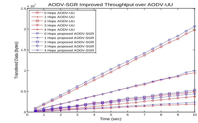
2.4 AODV and Throughput
Throughput is the measure of the rate successful data that is transferred through
the link. Considering a routing protocol like AODV, it is important to keep note that
maintenance packets will also take up space on the channel hindering throughput. This
realization is important because if AODV packet’s rate is decreased, logically throughput
and latency of the overall link should be improved, as shown in Figure 5. AODV-SGR is
15 | P a g e
Fig 5 AODV-SGR Improved Throughput over AODV-UU
Drawing from Figure 5, Figure 6 will extrapolate the date between AODV-SGR
and AODV-UU (unmodified implementation). AODV-SGR relies on reducing protocol
traffic, by throttling down maintenance traffic for static sensor networks. The data from
Figure 5 is extrapolated and easily identifiable in Figure. 6.
Fig 6 AODV-SGR Improved Throughput over AODV
0 1 2 3 4 5 6 7 8 9 10
0 0.5 1 1.5 2 2.5x 10
7 AODV-SGR Improved Throughtput over AODV-UU
Time (sec) T ra nsf er ed D at a (b yt es)
0 Hops AODV-UU 1 Hops AODV-UU 2 Hops AODV-UU 3 Hops AODV-UU 4 Hops AODV-UU
0 Hops proposed AODV-SGR 1 Hops proposed AODV-SGR 2 Hops proposed AODV-SGR 3 Hops proposed AODV-SGR 4 Hops proposed AODV-SGR
0 1 2 3 4
0 5 10 15 20 25
AODV-SGR Improved Throughtput over AODV-UU
16 | P a g e
Note that the general throughput decreases with the increase in hops. This result is
due to the fact that as the nodes increase, each node will receive data packet, process its
destination, and then resend on the proper route.
2.5 Wireless Links Utilized for AODV
AODV is independent of the link it utilizes, so this allows us to run the protocol
on any node utilizing WLAN, Zigbee, Bluetooth, or Cellular. AODV-UU, the code by
Erik Nordstrom from Uppsala University utilizes the WLAN links on Linux nodes,
running 2.6.x.x kernels.
For smart grid applications, longer range transmission links are required to bring
down cost and increase efficiency. Publicly available WLAN included in the setups
found in consumer laptops and cell phones has low range of around ~30 meters. The
limiting factor to transmission distance is the transmission power, antenna type, and the
environment. All these factors are important to keep in mind but can be overcome
depending on the resources and requirements. Transmission power and high gain
antennas come at the cost of power usage. Therefore depending on the sensors power
supply whether it is battery operated or plugged in into a power source, the system can be
setup. Sensors utilizing Zigbee or Bluetooth will be most likely running on shorter
ranges, even though there exists longer range communication antennas.
Qing in [19] shows that using cellular links in smart grid situations and power fault detection, yielded good results. Cellular networks make sense for nodes that would
be required to be outside of crowded cities. Nodes that are far away from population
centers would require many intermediate nodes just to relay information, which would be
17 | P a g e
Assuming the power constraints on the sensing nodes is not constrained, the
distance in nodes can be increased without worrying about power depletion. León et al. in [20], put forward the idea that the nodes, when not constrained, would still make a viable
solution utilizing multi-hop mesh network solution.
The number of ways that sensor data can be transmitted for long distances is
limited only by our imaginations. Marihart in [19] describes numerous technologies for
this application and summarizes their advantages and disadvantages. These technologies
range from twisted pair cables, power line carries, and optic fiber for wired solutions, to
microwave radios and satellites for wireless solutions. Cole in [20] illustrates how
satellites can be used by power companies to collect the usage information directly from
smart meters for near-real-time data collection. This topology would be especially useful
for dwellings in remote areas. The disadvantage though, would be the cost associated
with purchasing and launching several satellites into orbit, or paying for processing time
on existing orbiting satellites.
2.6 Summary
By now, an understanding of some of the different protocols developed for static
and mobile nodes should be achieved, as well as a general overview of the different
technologies that can be utilized to realize our purposes. Appropriate technologies must
be selected depending on the constraints of the system; therefore it is important to
18 | P a g e
Chapter 3 - AODV Overview and Test-Bed
AODV is the protocol chosen for this project. For the complete overview and
functionality of the AODV protocol, please refer to RFC3561 [4]. I will discuss its
functionality and provide an overview and a scenario of AODV’s operation in Section
3.1. Section 3.2, will provide some of the important parameters that are important for our
purposes. Section 3.3 will explore the requirements for the test-bed. Section 3.4, will
summarize our findings before we delve into the modifications of AODV in Chapter 4.
3.1 AODV General Functionality and Example Scenario
It is important to note that AODV was first created for mobile networks, instead
of static networks. AODV is an on-demand protocol, meaning a route will only be
established provided a node requested it. The AODV protocol relies heavily on "Hello"
messages, which are packets that are broadcasted, and when received replied to, to
establish a direct ―neighbor‖. These messages are sent out periodically and any neighbors
are added into a neighbor list, and deleted accordingly if communication is lost.
The "Hello" messages are periodically sent by each node at one second interval as
per the RFC3561 [4]. The "Hello" packet is in essence a RREP packet, with TTL set to 1.
If communication is lost with a neighbor, all nodes using the lost neighbor need to be
19 | P a g e
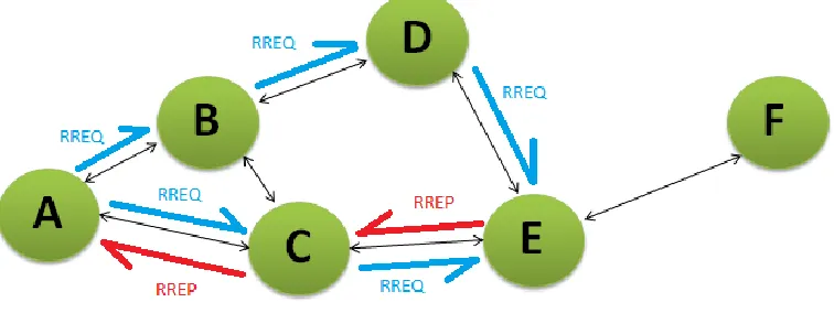
Fig 7 Explaining AODV, scenario
To establish a route in a scenario like Figure 7 from node A to F, node A first will
broadcast a RREQ packet. This packet is received by its direct neighbors; they will parse
and process it. The RREQ packet will include originator, destination, destination
sequence number, and lifetime.
First we will discuss the lifetime; the lifetime is included in the packet header and
dictates how many hops should the packet traverse before being marked invalid.. This
mechanism is useful if the RREQ was issued to lost or non-existent destination. AODV
uses an expanding-ring search algorithm. The first RREQ will include a short TTL, 2
hops by rfc3561, if the route is not established within 2 hops, the originator will send out
a new RREQ with a larger TTL, and again up to a certain limit. Expanding-ring search is
an intelligent route seeking scheme which will prevent overloading the system in case of
lost or nonexistent nodes.
The originator and destination fields are self-explanatory where the originator
field contains the IP of the node that originated the request and the destination field
contains IP of the desired destination. The sequence number is unique to the originator
and actually attributed to the route itself.
When node A needs a route, it will first check the routing table for a path to the
destination, if unavailable, a RREQ will be sent. The RREQ is rebroadcasted for any
nodes in range. Each node that receives a RREQ, in this case node B and C, they will
20 | P a g e
scenario node B and C both do not have the destination in their direct neighbors, and no
route established yet, therefore the RREQ is rebroadcasted. When node E receives the
RREQ, it will check the destination field. When the destination is cross referenced with
all its neighbors and route destination, it will receive hit on a node that is a neighbor.
Since node F is a neighbor of node D, and that is the destination on the RREQ received,
node D will reply with a RREP to the node that sent the RREQ. The RREP packet will
traverse down the network to create a symmetric unidirectional link to the originator.
It is worth noting that after node D sends a RREP back to node ―A‖, it will also
send RREP to node F to establish a route through D to A. This completes the route
request process, with a positive route established. The route will stay active as long as the
route is in use. If the route is not being utilized by any of the nodes, each precursor that is
part of the route will invalidate the route. This is a great feature when AODV is being
used in fast changing environments and on nodes with low resources.
So we have discussed the RREQ, RREP, and "Hello" message, which leaves us
the RERR message. The RERR is used to flag a dropped node or a broken route and
notify all other nodes which might have been used by other nodes as a precursor to a
route. The RERR can be broadcasted or unicasted for all effected precursors, if
broadcasting is inappropriate. When a node receives a RERR, it will check which node
the packet is concerning. After that the local node will check if the dropped node is part
of a route, a neighbor, or a destination in its local routing table. That way the node can
mark the affected routes appropriately.
Put simply, AODV manipulates the kernel routing table with destination and
gateway fields in order to allow messages to traverse properly through unidirectional
21 | P a g e
3.2 Important Parameters in AODV
AODV’s functionality is governed by important parameters that are outlined in
RFC3561. Some of the more pertinent parameters will be explored. Without loss of
generality, some of these parameters will be tuned to some of the requirements of smart
meters in Ontario. For example, in cities like London and Toronto utility companies
would like to have their smart meters data collected every 15 minutes and reported once
per day [23]. Since fifteen minute intervals will make data acquisition lengthy and
tedious in our test-bed, the assumed reporting time will be 10 seconds.
3.2.1 "Hello" Interval
In AODV-UU, the "Hello" Interval is set in the params.h file, and would be
accessed by the Hello_send () function. This parameter dictates how often are "Hello"
messages broadcasted. A "Hello" is a RREP packet, with TTL = 1. If a previously added
neighbor does not send a "Hello" within:
which is twice the "Hello" interval, the node will mark that neighbor as lost.
Consequently a RERR packet is then generated and also propagated through the network
as per Section 6.11 of RFC 3561 [4]. The neighbor link will be marked ―invalid‖ and
deleted after Delete Period, where:
( )
From the above key points, it is understood that as long as the ―Hello’s ―are periodically
sent at their set interval, and any active multi-hop routes are utilized before their set
22 | P a g e
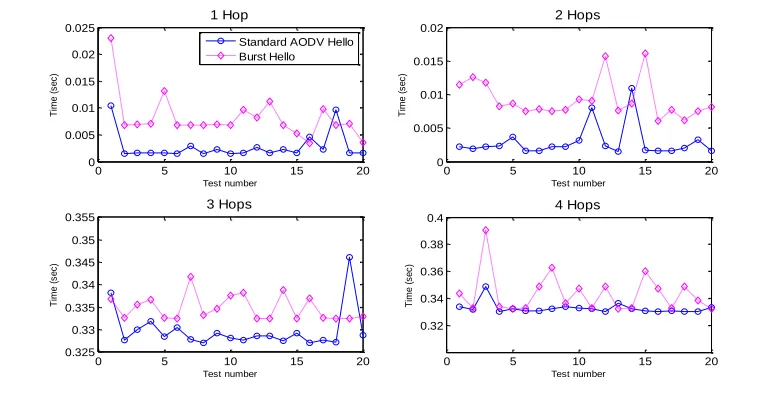
3.2.2 "Hello" Broadcast Mechanism
As Discussed in Section 3.1, AODV relies on periodic "Hello" messages to
establish direct neighbors. This is a very important mechanism, as without direct
neighbors no route can be achieved to any destination. Per the RFC3561 [4], AODV
nodes will establish and update their neighbor list at a period of one second. Our first
approach to modifying AODV was changing the ―Hello‖ interval, to send with varying
frequencies.. This burst mechanism would dynamically change the frequency throughout
the operation of AODV.
Fig 8 Burst vs Regular "Hello" Mechanism, AODV-UU
In Figure 8, we can see that the unmodified version of AODV consistently
outperformed AODV with burst "Hello" enabled. This was a surprising result, but was
attributed to phenomena observed where all nodes ended syncing up with each other
during "Hello" sending. This would spike traffic at certain times when the "Hello's"
would be broadcasted and processed. So the burst mechanism was ignored and decided to
go with a different approach.
3.2.3 Route Delete management
Now that we understand how AODV establishes routes, AODV also deletes
routes when not in use. The parameter that controls the timeout is Active_route_timeout.
0 5 10 15 20
0 0.005 0.01 0.015 0.02 0.025 Test number 1 Hop T im e ( s e c )
0 5 10 15 20
0 0.005 0.01 0.015 0.02 Test number T im e ( s e c ) 2 Hops
0 5 10 15 20
0.325 0.33 0.335 0.34 0.345 0.35 0.355 Test number T im e ( s e c ) 3 Hops
0 5 10 15 20
0.32 0.34 0.36 0.38 0.4 Test number T im e ( s e c ) 4 Hops Standard AODV Hello
23 | P a g e
This timeout is set to 20000ms or 20 seconds after a route has not been in use. This is
important and will be varied to identify its effect on the routing performance later.
3.3 Test-bed Requirements
When conducting multiple tests with different nodes, human error becomes
amplified. Manually entering rules, modifying Adhoc connections we were facing
problems that seemed serious at first but were due to simple errors.
To conduct any test on the Linux boxes, we were required to enter into an Adhoc
connection with static IPs on each node; this was due to multiple reasons. If the
connections where not setup in Adhoc the nodes would require a router to communicate.
Therefore, a static IP setup was implemented. This was achieved using iwconfig[24]and
ifconfig[25]. A typical script would look like:
#!/bin/bash
/etc/init.d/network-manager stop ' turn off automatic network selection
ifconFigure wlan0 down ' bring interface down, flushing settings
sleep 1 ' wait 1 second, allow all changes to take place
iwconFigure wlan0 mode Ad-Hoc ESSID aodv channel 5 ' settings for network
sleep 1 ' again wait
ifconFigure wlan0 up ' return interface back on
iwconFigure wlan0 mode Ad-Hoc ESSID aodv channel 5 ' reiterate settings to the
buffer, more consistent results
sleep 1
ifconFigure wlan0 ' check ifconFigure if settings carried through
ifconFigure wlan0 default 192.168.0.1 ' assign IP gateway to wireless
interface
ifconFigure wlan0 192.168.0.7 ' assign IP to wireless interface
iwconFigure
echo " The card shoud be set up to connect to aodv now with IP 192.168.0.7" '
24 | P a g e
Unfortunately this did not always result in a stable connection, so we decided to
utilize the built in network-manager [26]. The manual method sometimes resulted with
mismatched cells for the network, and required flushing the wireless configuration. A
mismatched cell on one of the nodes would render all test data collected in that test
suspect.
This was done without checking how the nodes were setup in respect of each
other. Using MAC-kill commands like:
“iptables -A INPUT -j DROP -m mac --mac-source xx:xx:xx:xx:xx:xx”
Therefore when changing test topologies, some rules in the Iptables would still exist, and
after time wasted it would be realized that the rules are not setup as previously thought.
Another important feature would be data collection from each node. After running
multiple tests, data concerning the test would be logged on each node. This data required
harvesting after the tests, and with some tests utilizing six or seven nodes, the data
harvesting would be tedious and error prone.
In conclusion the test-bed should be able to:
Find all nodes on the static network setup through network manager
Present a sort of GUI to setup the topology to test
Share test modules with each node (scripts to run on each node)
Wait till all tests have completed
Harvest test data from each node
3.4 Summary
A general idea of the "Hello"_interval and Route_delete_timeout was introduced as well as other parts of AODV’s functionality. The role of the RREQ, RREP, and
RERRs in AODV were presented as well, as they are the main packets that are used by
25 | P a g e
The test-bed will be a tool of great benefit to researchers studying AODV as well
as other protocols since it is protocol independent. In the next chapter the modifications
26 | P a g e
Chapter 4 - AODV-Modified for Semi-Static nodes with Test-bed
4.1 Overall Proposed Modifications to AODV
Smart meters are currently being deployed across Ontario, as well already being
utilized in countries like the United States, various countries in Europe, and other
provinces within Canada. The smart meters themselves will allow utility companies to
balance supply and demand much more efficiently, slowly alleviating (I don't know if
this is a word I don’t know, or what) the adverse global warming affects of coal and fossil
fuel plants. These meters will also facilitate the consumer push to personal wind and solar
energy harvesting. The communication system which is currently being utilized is known
as the advanced metering infrastructure (AMI). Many companies are already specializing
in designing, developing, and deploying the devices which will be operable on AMI. For
the smart grid, with communication systems still in their infancy, this project aims to
bring a novel approach to data collection.
27 | P a g e
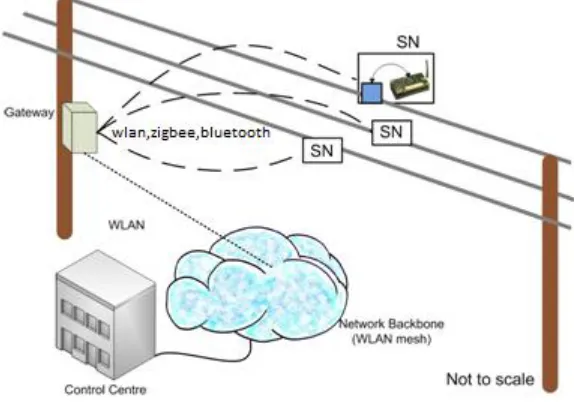
In Figure 9, the system overview of the sensors on transmission lines that will
relay data back to control center through an essentially transparent cloud of mesh
communication is presented. The AODV modifications presented in this project will
bring forth a viable communication protocol that will fill that gap. The sensors on the
transmission lines do not necessarily need to be on preconfigured manually to
communicate with other sensors. The collector node labeled ―gateway‖ , will instead
collect sensor data and then transmit to the control center through the mesh network.
We will assume that all sensor devices use WLAN, as their wireless option for
communication. Discussed in Section 2.4, AODV and other communication protocols are
essentially link independent, therefore any wireless link can be used with certain
modifications to the back end of the protocol.
For this project, there is a major emphasis on the control center, and the
realizations that all mesh network nodes are primarily required to report back to the
control center. AODV has no hierarchy to any node in the mesh network, but in a smart
grid scenario routes between any node and the control center are our primary concern.
Additionally, it would be required that all nodes being used as hops for a route leading to
the control center will have to maintain precursor links and report breaks in order to
reestablish new links for any node that is concerned. Therefore it is required for the
protocol to guarantee a route that is always usable from every node to the control center,
providing there are available hopping nodes, and the links between said nodes are
healthy.
4.2 Hardware and Software
4.2.1 Hardware
The modified protocol was designed and tested in lab. This required hardware,
and a coded implementation of the protocol. The base code used for this project was
AODV-UU version 0.9.6. All modifications were tested using a variety of industry
standard tools discussed later.
New AODV node
added to network.
1
Send RREQ to
control center
when found,
initiate keep route
28 | P a g e
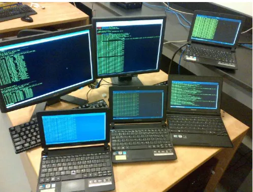
Fig 10 Project test-bed (Hardware)
The hardware in Figure 10 consisted of 6 nodes, running the same copy of
Modified and Unmodified AODV. All nodes were required have 2.6.35 Linux kernel, for
the backend mechanisms of AODV-UU 0.9.6 to run. The test-bed is described with an
overview of its hardware in table 4.1.
Table 4.2: Hardware Test-Bed description 1
Computer Wi-Fi
Card
Processor Kernel
1 b/g/n 2.0 Ghz Dual core 2.6.35
2 b/g/n 2.0 Ghz Dual core 2.6.35
3 b/g/n 1.6 Ghz Single core 2.6.35
4 b/g/n 1.6 Ghz Single core 2.6.35
5 b/g/n 1.6 Ghz Single core 2.6.35
29 | P a g e
4.2.2 Software Testing Tools (from paper for refs)
A number of different tools and utilities were utilized for network performance
testing and solving for different metrics which would measure the performance of the
proposed system versus the original AODV-UU system. They are as follows:
Iperf v2.0.4 [11]- for bandwidth testing with half second bandwidth reporting
“iperf –c xxx.xxx.xxx.xxx –i0.5 ”
Ping utility, iputils-sss20071127 [12]– used to test end to end latency after a route has
been established. The ping command utilized the ―-R‖ switch to make verify the route each ping packet used. The ―-c1000‖ switch ran a 1000 iterations and ―-i0.05‖ waited
50ms between successful pings.
“ping –R –c1000 –i0.05 xxx.xxx.xxx.xxx”
Iptables v1.4.4 [13]– to simulate out of range scenario and force multihop routes. To do
so, we asked the kernel to drop packets with certain MAC addresses.
“iptables -A INPUT -j DROP -m mac --mac-source xx:xx:xx:xx:xx:xx”
AODV-UU v0.9.6 – The debug reporting native to AODV-UU was altered to output data
pertinent to our data mining scripts, that solve for such things as Route setup times,
polling broadcasted messages, and monitoring kernel calls for routing table functions.
VB6, C, Bash, Matlab - multiple programming languages were used to generate scripts
which were involved in time stamping network data, performing calculations, retrieving
30 | P a g e
4.3 System Requirements and the Shortfalls of Unmodified AODV
Firstly, this section will discuss where unmodified AODV fell short on
requirements for semi-static node systems like smart grids. Since AODV is an on demand
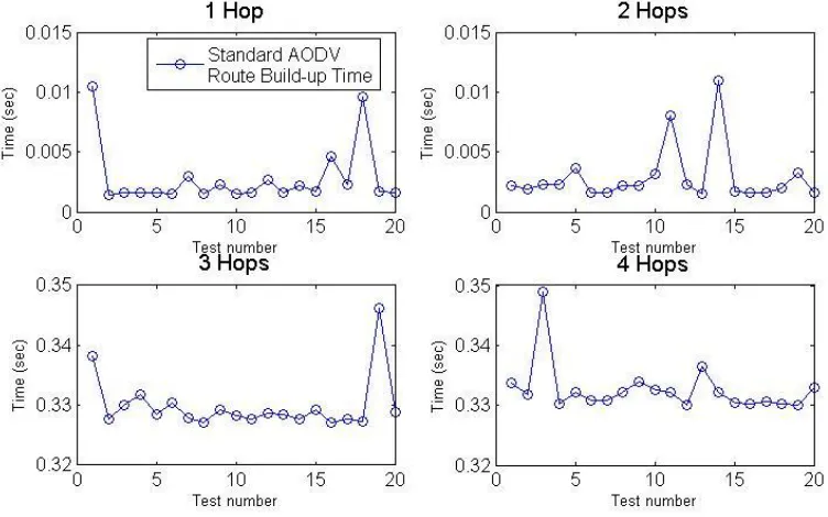
system, longer multi-hop routes would take time to setup. The Route establishment time
ranged between 50ms for 1 hop (3 nodes) and about 340 ms for 4 hops (6 nodes), as
shown in Figure 11. It is worth noting that some of the spikes in the times observed were
hard to reproduce at exact intervals. Therefore the spikes are attributed to unknown
sources either within the kernel, or wireless interference.
Fig 11 Unmodified AODV route build time
Since routes are created after the request is detected up by unmodified AODV's
kernel module, applications might time out and report a failed send. To further prove this
point, the tests showed a that the Unmodified AODV's first ―ping‖ packets issued by the
ping application would get dropped due to no route being available, and overstepping the
31 | P a g e
Table 4.3 Dropped Packets For Unmodified AODV in multi-hop
Iteration Packets sent Packets Received Percentage of packets lost
1 100 92 8%
2 100 93 7%
3 100 93 7%
4 100 67 33%
5 100 92 8%
Wireless card were selected with drivers available that will run Ad-Hoc mode in
Linux. The e-machines net books had internal wireless cards that had Ad-Hoc drivers,
and all cards were 802.11 b/g/n. As for the desktops, external USB cards were purchased
that met two requirements. The wireless cards had to match the classification of all the
other nodes in terms of 802.11 (a/b/g/n), the wireless cards also need to have drivers that
were tested with Linux machines to work in Ad-Hoc mode.
When testing Unmodified AODV, random link breaks were observed as well.
There was no immediate indication to why these breaks would occur, but they were
documented regardless in Table 2.4.2. AODV-UU presents the option of running the
protocol with debugging enabled, giving a glimpse into the inner workings of kernel
calls, to processing and sending maintenance packets. These drops were characterized by
a link break with immediate neighbors, then immediately re-adding the neighbor after the
next "Hello" message comes in.
As for the operating system, the AODV-UU README file documents the following is required:
* Linux OS (2.4.x, 2.6.x).
* Kernel with Netfilter support.
Most Red Hat/Fedora kernels have this support.
32 | P a g e
Looking for a friendly Linux flavor to use on all nodes, Linux mint 9
[http://linuxmint.com/] was chosen. Linux Mint 9, comes with a kernel that meets the
specifications and a rich application repository setup that was very user friendly to
experienced and novice users alike.
4.4 Control Center Graphical User Interface
In section 3.3, the required proposed requirements for the test-bed were:
Find all nodes on the static network setup thought network manager
Present a sort of GUI to setup the topology to test
Share test modules with each node (scripts to run on each node)
Wait till all tests have completed
Harvest test data from each node
Reset all configurations and be ready for a new test
The GUI was developed as a collaborative effort using the Netbeans Java IDE.
The final version of the test-bed met all the required specifications put forth in section
3.3. Figure 12 presents the IDE work area. Figure 13 presents the finished GUI in its
standby state.
The test-bed will ask the user for the number of nodes in the test. When the
number of nodes on the testing network is entered, the "find nodes" button will initiate a
scan of all available nodes up till the number of nodes entered. The nodes are then added
to a drop down list with their IP and hostname visible. All these features insure the test
that will be ran, is what the researcher is aiming for and preventing mistakes.
The test-bed consists of a server side and a client side. The server side will log all
the client nodes running a copy of the test-bed and grab the IP and host name of the
33 | P a g e
available. A built in throughput test, based on the "Iperf" application for Linux, or a script
runner.
The Iperf utility is a widely used throughput testing program that will require the
IP of the node to be tested as the bare minimum. The test-bed uses the "-t" switch on the
program to specify a time for the test to run, and this will give the researcher a clear
throughput output on both the client and server side.
34 | P a g e
Fig 13 Test-bed GUI -clean
The test-bed was also developed with a script run and data harvest feature. First,
the script or test module will be linked to the test-bed. Then the test-bed will ask for
which node is the script or module pertaining to. When the script run button is pressed,
the module is shared with the node the researcher wants the module to run on, and the
data will be collected after the test is complete.
The mechanism to run the script share will first open a socket to the node that will
run the test. The server is the node where the researcher is conducting tests, and the client
is the node which tests will run from. The server will send a packet stating this is a script
based test. After that, the client will open another socket to receive the script on. The
script is then uploaded to the client. Upon successfully receiving the test script, the client
will run the script and log all test data to a folder set up by the test-bed (client-side). After
35 | P a g e
mechanism is utilized for the built in "Iperf" tests, but the script tests allow variety in
testing. The following chart illustrates the script based test.
START
Read Test
Execution node
Read Script
filename to run
Build command to run
script
Open Socket Connection
to test node
Send script execution
command
Close Socket Connection
to test node
END
36 | P a g e
4.5 AODV Protocol Modifications
Unmodified AODV's unmodified operation was discussed in section 3.1, and
some of the shortfalls for a static network were discussed in Section 4.3. The
requirements for a proposed communication protocol should include:
Low end to end to latency, will be compared to manually set network
Stable and acceptable throughput rates
Decrease or eliminate RREQ times
The requirements will also have to be dynamic and retain the maintenance
robustness of Unmodified AODV. The main mechanisms that were modified, will be
discussed, and the results presented in the next section.
In a smart grid scenario, there is always an emphasis on the control center. Every
node is required to report its acquired data back to the control center, or in case of an
emergency to be able and relay information immediately to the control center. In the
modified version of AODV presented in this project, a mechanism was added to
dynamically share the control center address with every node and create a route to the
new control center. This route will be kept up as long as the route is available. If there is
a break anywhere in the link, RERR will traverse the network and alert all nodes to take
proper precautions concerning the node that is down.
To share the control center, the new RCC packet was added to the protocol. This
packet is utilized when sharing the control center address with direct neighbors. The
37 | P a g e
Figure 15 RCC packet structure
The RCC packet is simpler in comparison to the other packet employed by
Unmodified AODV-UU. The packet includes:
The type of the packet (RCC in this case, picked up in aodv_socket.c)
9 bits reserved for future work
Destination IP : Destination for the packet
Originator IP: The address of the originator
Control Center Address: The address of the control center being shared
4.5.1 Throttling down "Hellos" and extending Routes
Due to the static nature of the nodes in smart grid sensors, the one second "Hello"
interval is not necessary anymore. When all the nodes are broadcasting "Hello's" within
range, they broadcast at staggered time slots, each received message will be processed by
each node. The extra traffic on the channel and processing required for each message will
slow the system down. Therefore the rate can be decreased.
It is important to note that the "Hello" broadcast period needs to be tuned with
care. Real world testing with more nodes would be required to establish the ideal rate for
any given setup. When a node is set to a certain "Hello" period, other nodes need to
38 | P a g e
governs the neighbor links. If a node does not receive a "Hello" from its neighbor before
the route delete timeout, the link will be invalidate and the neighbor assumed lost.
If the "Hello" period is chosen to be much longer, for example one hour;
neighboring nodes will also require a route delete timeout to take into account the longer
"Hello" interval. Such a modification would free up the channel, on the other hand it will
take up to an hour to register a node as missing if it ever experiences difficulty.
Fig 16 Burst Mechanism flowchart
Referring to Section 3.2.2, a burst "Hello" mechanism was tested with surprising
results. The burst mechanism was simple, it would switch from one second intervals, to 5
second intervals, to 10 second intervals as illustrated in Figure 14. After observing the
debugging outputs, all nodes within range of each other seemed to sync and cause
undesirable effects on latency. When all nodes are set with the same "Hello" period,
performance was scalable.
Burst
Mechanism
10 sec for 5 iterations
1 sec for 20 iterations 5 sec for
39 | P a g e
To demonstrate a tangible change to the system, the "Hello"_interval will be set to
10 seconds in params.h of AODV-UU.
#define "Hello"_INTERVAL 1000// changing this value changes "Hello"
interval
#define "Hello"_INTERVAL 10000 // changed to 10000ms or 10 seconds
4.5.2 Control Center Mechanism
Fig 17 Sensor nodes with paths to control center
Figure 15, shows how nodes placed at random with routes established to the
control center. Unmodified AODV will only create routes to the control center if the node
requests such a route. There is currently no mechanism in Unmodified AODV that will
allow multiple nodes to create and keep up a route to an important node like the control
center. There is also no mechanism to maintain the address of the control center.
There would be a need for an external application or service that will update the
control center address if it changes. In this project, the auto update feature and route
40 | P a g e
deployment of nodes, as they will receive the control center address from neighboring
nodes, eliminating user error.
As for keeping the route up, there were two ways to go about this. One way is
altering the mechanism AODV maintains current routes. The values for timeouts could
be set dynamically in the code itself. The other way would be to periodically "ping" or
poll the control center. Both ways have advantages and disadvantages discussed in table
4.3.
Table 2 4.5 Summary of methods for Keeping a Route Alive
Routing Manipulation Cross network Polling
Advantages Changes are guaranteed
No extra network traffic required
Uses existing mechanism in
AODV, and already available in
AODV-UU
Disadvantages Room for error with wrong
routes, being kept alive.
Managing the routing table
dynamically is complicated
Increases Network traffic
Might adversely affect
throughput and latency.
Routing Manipulation:
To manually keep the route up, we will first have to find out if the node in
question is receiving and forwarding a route for the control center. This can be achieved
through reading and logging each RREQ packet.
In the code from Unmodified AODV-UU, the aodv_rreq.c file contains a
function called
rreq_process(), below is part of the function.
void NS_CLASS rreq_process(RREQ * rreq, int rreqlen, struct in_addr ip_src,
struct in_addr ip_dst, int ip_ttl, unsigned int ifindex)
41 | P a g e
rreq_dest.s_addr = rreq->dest_addr;
rreq_orig.s_addr = rreq->orig_addr;
rreq_id = ntohl(rreq->rreq_id);
rreq_dest_seqno = ntohl(rreq->dest_seqno);
rreq_orig_seqno = ntohl(rreq->orig_seqno);
rreq_new_hcnt = rreq->hcnt + 1;
// check if the originator or the destination is the control center, and log the ips to keep the route up
// cc_fts is a flag signifying this node currently posses a control center address
if (cc_fts ==1 && (rreq_orig.s_addr == cc_addr.s_addr || rreq_dest.s_addr == cc_addr.s_addr))
{
cc_imp_rreq = rreq_orig;
cc_imp_rrep = rreq_dest;
}
When we log the route request addresses we can now save the IPs that will be
used for a route lookup later. The originator creates the RREQ, the destination will
initiate a RREP, and both the RREQ and RREP are required to create a symmetrical link.
Both addresses were used to periodically renew the routing table fields associated with
them. Unfortunately, this approach did not provide the expected results. Dropped packets
were observed across 4 hop routes to the control center, even after the routes were locally
refreshed. Therefore it was decided to go with the polling of the route.
Polling The Control Center:
The polling mechanism was simpler to insert into the code and check for
![Fig 1 Hydro One Smart Meter – [http://www.hydroone.com/SiteCollectionImages/hero/smart_meter_01.jpg]](https://thumb-us.123doks.com/thumbv2/123dok_us/1416600.1174206/17.612.194.397.97.304/fig-hydro-smart-meter-hydroone-sitecollectionimages-smart-meter.webp)
![Fig 2 Wireless Sensors in a City Grid [http://images.fastcompany.com/upload/smart-grid-city.jpg]](https://thumb-us.123doks.com/thumbv2/123dok_us/1416600.1174206/19.612.109.549.69.291/wireless-sensors-city-grid-images-fastcompany-upload-smart.webp)
![Fig 4 After GPS routing, RREQ [18]](https://thumb-us.123doks.com/thumbv2/123dok_us/1416600.1174206/25.612.148.406.149.324/fig-after-gps-routing-rreq.webp)