İSTANBUL TECHNICAL UNIVERSITY INSTITUTE OF SCIENCE AND TECHNOLOGY
M.Sc. Thesis by Başak ÖZ
Department : Aeronautical and Astronautical Engineering Programme : Aeronautical and Astronautical Engineering STRUCTURAL ANALYSIS OF CYLINDRICAL SANDWICH SHELLS
UNDER UNIFORM AND IMPACT LOADING
İSTANBUL TECHNICAL UNIVERSITY INSTITUTE OF SCIENCE AND TECHNOLOGY
M.Sc. Thesis by Başak ÖZ 511071140
Date of submission : 20 December 2010 Date of defence examination: 27 January 2011
Supervisor (Chairman) : Members of the Examining
Committee :
Prof. Dr. Zahit MECİTOĞLU (ITU) Prof. Dr. Ata MUGAN (ITU)
STRUCTURAL ANALYSIS OF CYLINDRICAL SANDWICH SHELLS UNDER UNIFORM AND IMPACT LOADING
Assoc. Prof. Dr. Vedat Z DOĞAN (ITU)
İSTANBUL TEKNİK ÜNİVERSİTESİ FEN BİLİMLERİ ENSTİTÜSÜ
YÜKSEK LİSANS TEZİ Başak ÖZ
511071140
Tezin Enstitüye Verildiği Tarih : 20 Aralık 2010 Tezin Savunulduğu Tarih : 27 Ocak 2011
Diğer Jüri Üyeleri :
Prof. Dr. Ata MUGAN
SİLİNDİRİK SANDVİÇ KABUKLARIN SABİT VE DARBE YÜKLERİ ALTINDA YAPISAL ANALİZİ
Tez Danışmanı : Doç. Dr. Vedat Z DOĞAN (İTÜ) Prof. Dr. Zahit MECİTOĞLU (İTÜ)
(İTÜ)
FOREWORD
I would like to thank and express my deep appreciation for my advisor, Vedat Ziya DOĞAN. I am very glad to be completing my Masters Thesis at ITU and for the opportunities provided to me.
İBAÇOĞLU and Namık ALPAYDIN. Many thanks to all of my friends at TURKISH TECHNIC and ISTANBUL TECHNICAL UNIVERSITY, especially Haldun Hakan CÜZDAN, Ömer Faruk ÇALIŞKAN, Hafize Ebru SEVGİ, Seyit TOPAL, Hasan KÖRÜK and Oya EZER for their great support and encouragement. For his great effort on my completing the experiments I would like to thank to Müslüm ÇAKIR as well.
Special thanks to Emre YÜZBAŞIOĞLU for her preventing me from giving up and being with me in my tough times.
Most importantly, I owe my mother, Yüksel ÖZBAĞIR, a dept of gratitude for her efforts throughout her life in raising me to my current standing without getting bored or tired.
December 2010 Başak ÖZ
Aeronautical Engineer
TABLE OF CONTENTS
Page
4.1 General Solution for Orthotropic-Sandwich Cylindrical Shells Under Axially
FOREWORD... v
3.6.2 Forced vibration response of a sandwich plate subjected to dynamic 3.2 Anisotropy Concept... 12
3.1 Properties and Advantages of Sandwich Structures...10
3. SANDWICH STRUCTURED COMPOSITES ... 92.1.6 Combined composites ... 8
2.1.3 Flake composites... 6
2.1.2 Particle composites... 6
2.1 Clasification of Synthetic Composites ... 5
1. INTRODUCTION... 1
TABLE OF CONTENTS...v ii ABBREVIATIONS ...ix
LIST OF TABLES ...xi
LIST OF FIGURES ... xiii
SUMMARY ...xv
2. GENERAL OVERVIEW OF COMPOSITE MATERIALS ... 3
2.1.1 Fiber composites ... 5
2.1.4 Laminar composites ... 6
2.1.5 Filled composites ... 6
3.3 The Physical Meaning of Composites of Orthotropic Elastic Tensor... 14
3.4 Laminate Analysis... 15
3.4.1 Stiffness matrices for a midplane symmetric sandwich structure ... 18
3.5 Bending of Laminated or Sandwich Plates: Classical Theory ... 19
3.5.1 Boundary conditions... 21
3.6 Dynamic Effects on Sandwich Plates... 22
3.6.1 Natural flexural vibrations of sandwich plates ... 23
loading... 24
4. ANALYSIS OF CYLINDRICAL SANDWICH SHELLS ... 27
Symmetric Loads... 32
5. IMPACT ANALYSIS ... 35
5.1 Impact On A Simply Supported Plate ... 35
5.2 Impact on Sandwich Structures... 36
6.1 Pressure Load ... 41
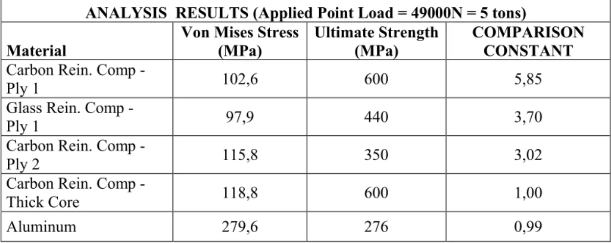
6.2 Point Load ... 42
6. NUMERICAL ANALYSIS ... 39
6.3 Impact Load... 42
6.4 Analysis for Validation with Experiments ... 43
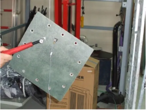
7. EXPERIMENTAL ANALYSIS ... 45
8. CONCLUSION... 49
8.1 Case 1 - Evenly Distributed Pressure Load... 49
8.2 Case 2 – Point Load... 51
8.3 Case 3 – Impact Load... 51
8.4 Comparison of Abaqus and Experiment Results... 52
8.4.1 Free vibration ... 52
8.4.2 Impact analysis... 53
REFERENCES ... 59
APPENDICES ... 61
ABBREVIATIONS
aij :compliance matrix Cijkl :elasticity tensor D : bending rigidity E :modulus of elasticity F :forcing function G :shear modulus h :plate thickness hc :core thickness
i (=x,y,z) :indices for general coorinates K : inplane stiffnesses
k : elastic modulus of the foundation
m,n :wave numbers
M :stress couples per width N :stress resultants per width
Q :transverse shear resultants per width p :dynamic lateral load
P : convolution integral tf :face thickness
u0, v0 :midsurface displacements Vn :effective shear resultant u,v,w :displacements
[A] :extensional stiffness matrix
[B] :bending stretching coupling matrix [D] :flexural stiffness matrix
( )f,( )c : subscripts for face and core
( )n,( )t : subscript for normal and tangential directions ( )u,( )v,( )w :subscripts for directions of displacements α,β :rotations
ε0 :midsurface strains εij :shear strains
κ :curvature
ν :Poisson’s Ratio σii :normal stresses σij :shear stresses
qmn :coefficient of lateral load function θ : circumferential coordinate
ωmn :natural frequency
LIST OF TABLES Page Table 6.2 : Table 6.3 : Table 8.1 : Table 8.2 : Table 8.3 : Table 8.4 : Table 8.5 : Table 8.6 : Table 8.7 :
Table 6.1 : Material Properties [16, 19]... 41
Velocity Calculation... 42
Velocity Calculation for the Small Shell... 43
Elastic Properties [18, 20]... 49
Maximum Von Mises Stresses... 50
Results for 2MPa Evenly Distributed Pressure... 50
Results for Point Load Applied at the Middle... 51
Results for Impact Load ... 52
Frequency Results of Abaqus Analysis... 52
LIST OF FIGURES Page Figure 2.2 : Figure 2.3 : Figure 2.4 : Figure 2.5 : Figure 4.1 : Figure 4.2 : Figure A.1 : Figure A.2 : Figure A.3 : Figure A.4 : Figure A.5 : Figure A.6 : Figure A.7 : Figure A.8 : Figure 3.2 : Figure 3.3 : Figure 3.4 :
Structure of a Composite Panel ... 10
Stress Distribution Over A Sandwich Model... 11
Stress Distribution Over A Homogenous Model... 12
Laminate Sequence... 7
Lamina and Laminate ... 7
Figure 3.1 :Assembled Composite Sandwich... 9
Figure 7.2 : Figure 8.1 : Figure 8.2 : Figure 8.3 : Figure 8.4 : Figure 8.5 : Figure 8.6 : Figure 8.7 : Figure 8.8 : Figure 8.9 : Figure 8.10: Rigid Modes of Glass Reinforced Composite... 53
Rigid Modes of Carbon Reinforced Composite... 53
Strain Plot of Circumferential Direction – Abaqus... 54
Strain Plot of Circumferential Direction - Experiment... 54
Strain Plot of Longitudinal Direction - Abaqus... 55
Strain Plot of Longitudinal Direction - Experiment... 55
Strain Plot of Circumferential Direction – Abaqus... 56
Strain Plot of Circumferential Direction - Experiment... 56
Strain Plot of 45° Direction - Abaqus... 57
Strain Plot of 45° Direction - Experiment... 57
Von Mises Stress ... 62
Displacements... 63
Von Mises Stress ... 64
Displacements... 65
Von Mises Stress Distribution... 66
Displacement Distribution... 67
Modes of the Free Vibrated GRC Shell... 68
Modes of the Free Vibrated CRC Shell... 69
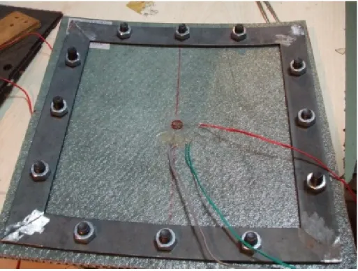
Strain Gauge Alignment ... 47
Positive Directions of Stress Resultants and Stress Couples... 28
Circular Cylindrical Shell... 27
Figure 3.5 : Figure 3.6 : Figure 3.7 : Figure 7.1 :Impact Testing on Glass Reinforced Composite Shell... 46
Representative Forcing Functions ... 25
Cross Section of A Symmetric Structure... 18
Nomenclature for the Stacking Sequence... 15
Sandwich Structures With Foam and Honeycomb Cores... 7
Classification of Synthetic Composites... 5
SUMMARY
Composites are becoming an important part of today’s materials because they offer great advantages such as low weight, corrosion resistance, improved fatigue and impact strength, faster assembly, low thermal conductivity, etc. Nowadays, composites are used in so many different areas ranging from automotive industry to golf clubs, making aircraft strctures to electronic packaging, sport requisites to medical equipment, space vehicles to home building. They consist of two or more combined constituents that are combined at a macroscopic level in order to gain better qualifications regarding chemical and physical properties. The properties of the mareials that are used to form the composite material can be separetely seen in the properties of the final product. The properties of the composites can vary by changing the matrix material, fiber orientation, the number of the fibers, the thickness of the layers...etc.
As aerospace engineers, we can often come across with composites in our area. A group of laminated composites used extensively is sandwich composites. Sandwich panels consist of thin facings (also called skin) sandwiching a core. The facings are made of high-strength material, such as steel, or composites such as graphite/epoxy; the core is made of thick and lightweight materials such as foam, cardboard, plywood, etc. The advantage in weight and bending stiffness makes sandwich panels more attractive than other materials. Sandwich panels are evaluated based on strength, safety, weight, durability, corrosion resistance, dent and puncture resistance, weatherability, and cost.
Mainly, the researches that have been done so far are related with optimization of composites, delamination of the layers or repair techniques of them. There are also many studies concerning the behaviour under an impact and vibration analysis of composite panels and shells. In this study, static and dynamic behaviour of sandwich structured composite shells is discussed. The material characteristic is changed by changing the core thickness, the material of the face sheets and the fiber orientation. Comparison between a cylindrical aluminum plate and a composite plate having the same dimensions is made. Different load types are applied on the sandwich model, stress-strain and displacement values are compared between different models. The optimum (having the minimum weight and most desired results) material type and orientation is tried to be reached. Since this is a comparison based study, the UNDER UNIFORM AND IMPACT LOADING
STRUCTURAL ANALYSIS OF CYLINDRICAL SANDWICH SHELLS
materialproperties are taken to be linear and the boundary conditions are encastered. For all numerical solutions ABAQUS 6.9 is used.
This research will show us how the behaviour of sandwich structured composite having a cylindrical shape changes according to changing thickness and fiber orientation under general vibration and impact loads. The analysis can be improved for more various configurations (having different core material, various load conditions, etc.)
SİLİNDİRİK SANDVİÇ KABUKLARIN SABİT VE DARBE YÜKÜ
ÖZET
Düşük ağırlık, korozyon dayanımı, yüksek yorulma limiti ve çarpma dayanımı, hızlı montaj edilebilmeleri, yüksel termal iletimleri gibi özellikleri sayesinde günümüzde önemli kullanım alanına sahiptirler. Otomotivden golf sopalarına, uçak yapılarından elektronil paketlemeye, spor malzemelerinden tıbbi gereçlere, uzay araçlarından bina yapımına kadar pek çok değişik alanda boy göstermektedirler. Daha iyi kimyasal ve fiziksel özelliklere kavuşmak için kompozitler gözle görülür seviyede iki veya daha fazla bileşenden meydana gelirler. Son üründe onu meydana getiren alt ürünlerin özellikleri ayrıayrı görülebilir durumdadır. Kompozit malzemenin özelliği matrix malzemesini, fiber oryantasyonunu, fiber sayısını veya katman kalınlıklarını değiştirerek değiştirilebilir.
Uçak mühendisleri olarak alanımızda kompozit malzemelere sıkça rastlarız. Sıkça kullanılan katmanlı kompozitlerin başında sandviç kompozitler gelir. Orta kısımda kalan nispeten kalın ve yumuşak olan dolgu malzemeyi iki taraftan daha ince ve dayanımı yüksek tabakalar sıkıştırır. Dış tabakalar, yüksek dayanımlı çelik veya kompozit olabilir, dolgu malzemesi olarak da düşük yoğunluklu köpük, bal peteği gibi malzemeler kullanılır. Kompozit malzemeler ağırlıkları, yüksek dayanımları, hava koşullarından az etkilenmeleri ve maliyetleri yönünden tercih edilirler.
Şuana kadar yapılan araştırmalar çoğunlukla kompozitlerin optimizasyonuveya delaminasyonu üzerinedir. Çarpaya yükü altında kompozitlerin dayanımı veya titreşim analizlerini konu alan pekçok araştırmaya rastlamak da mümkündür. Bu çalışmada kompozit kabuğun fiziksel özellikleri değiştirilerek düzgün dağılmış basınç altında veçarpmaya maruz kaldığında nasıl davranacağı incelenmiştir. Aynı zamanda titreşim analizleride yapılarak doğal frekansları karşılaştırılmıştır. İncelemeler karbon takviyeli ve cam takviyeli kompozitler, ve aynı ölçülerde aluminyum plaka üzerinde yapılmıştır. Minimum ağırlıkla en iyi sonuç veren malzemenin seçimi hedef alınmıştır. Kıyaslama bazlı çalışıldığı için malzeme özellikleri lineer, sınır şartları ise ankastre alınmıştır. Nümerik çözümler için ABAQUS 6.9 kullanılmıştır.
e ve yükler altında nasıl davrandığını gösterir. Bu çalışmanın bir ileriki safhası değişik sınır şartlarında ve lineer olmayan malzeme özellikleriyle araştırma kapsamının genişletilmesi olacaktır.
ALTINDA YAPISAL ANALIZI
1. INTRODUCTION
As commented by Rahmani and his coworkers [1] sandwich structures with laminated polymer matrix composite face sheets and a foam or low strength honeycomb core are being used increasingly in aerospace, automobile, locomotive and construction industries for their excellent properties. In their study they deal with the free vibration analysis of composite sandwich cyrindrical shell with a flexible core using a higher order sandwich panel theory. To extend the knowledge of mechanical properties both on single components and on complete structures, focusing on the effects induced by different kind of skin arrangements many studies are present [2, 3]. Layerwise finite element models are developed by Moleiro and his coworkers [4] based on a mixed least-squares formulation for both static and free vibration analysis of multilayered composite plates. In this research area there are also studies based on sandwich structured beams. In one of them [5] a method, based on Reissner's formulation, is developed to improve the accuracy for new sandwich structures.
Reducing the weight has always been the most critical issue in all kinds of optimization technique. In their study Walker and Smith [6] has developed a methodology to select the best material combination and optimally design composite sandwich cylinders having fibre reinforced skins and low density cores for minimum mass.
Most of the previous studies have focused on the strength capacity of sandwich structures under quasi-static loading. However, Meo et al. [7] called attention to the response of sandwich composite structures to impact loadings. Again Meo et al. [8] has investigated the potential hazards resulting from a low-velocity impact (bird-strike, tool drop, runway debris, etc.) on aircraft structures, such as engine nacelle or a leading edge. Study of soft body impact damage in fibre reinforced composite structures is done by Johnson and Holzapfel [9].
Similarly, the composite sandwich structures response to bird strike have also been the focus of various researchers. Nowadays the risk of structural and system failures, as well as of occupant injuries, due to bird strike events is well recognised in aircraft design. Different structural parts of airplanes and helicopters are currently designed to deflect the impacting body trajectory and to partially absorb its impact energy in order to protect the primary structures in the event of bird strike. In order to fulfil these requirements, the bird impact response of windshields, wing or tail empennage leading edges, as well as engine nacelles, are evaluated by means of intensive experimental and numerical activities as given in [10, 11, 12].
In the study of Hanssen et al. [13] experimental bird-strike tests have been carried out on double sandwich panels made from AlSi7Mg0.5 aluminum foam core and aluminum AA2024T3 cover plates. The bird-strike velocity varied from 140 to 190m/s. The test specimens were instrumented with strain gauges in the impacted area to measure the local strains of the rear sandwich plate. The bird was represented by an idealised geometry and the material model was defined by a linear equation-of-state. Similarly the use of aluminum foams as filler materials in aeronautical leading edges is investigated in other studies as well [14]. Particularly, the improvement of the mechanical behaviour of the filled structure respect to the hollow one is analysed by means of standard bird strike impact tests.
The scope of the present study can be defined as comparing composites that have different physical characteristics and comparing them with commonly used metals as well. Moreover, at the end of the study the results obtained from abaqus and experiments are compared to understand the reliability of the testing apparatus.
2. GENERAL OVERVIEW OF COMPOSITE MATERIALS
Composite materials consist of two or more materials combined in such a way that the individual materials are easily distinguishable. One constituent is called the reinforcing phase and the one in which it is embedded is called the matrix. The reinforcing phase material may be in the form of fibers, particles, or flakes. The matrix phase materials are generally continuous. The reinforcement is usually much stronger and stiffer than the matrix, and gives the composite its good properties. The matrix holds the reinforcements in an orderly pattern. Because the reinforcements are usually discontinuous, the matrix also helps to transfer load among the reinforcements. Examples of composite systems include concrete reinforced with steel and epoxy reinforced with graphite fibers, etc. We can classify wood as one of the oldest and best known natural composites that includes cellulose fibers in a matrix of lignin [21].
Reinforcements basically can be counted in three forms: particulate, discontinuous fiber, and continuous fiber. If a particle has roughly equal dimensions in all directions such as gravel, microballoon, and resin powder, they are called particulate reinforcements. Reinforcements become fibers when one dimension becomes long compared to others. Discontinuous reinforcements (chopped fibers, milled fibers, or whiskers) vary in length from a few millimeters to a few centimeters. Most fibers are only a few microns in diameter, so it doesn't take much length to make the transition from particle to fiber. Fibers are the pricipal load carrying members and occupy the largest volume fraction.
Typologies of fibre-reinforced composite materials: a) continuous fibre-reinforced
b) discontinuous aligned fibre-reinforced
Figure 2.1 : Typologies of Fibre-Reinforced Composite Materials [21] The matrix must transfer the load at very short intervals with either particles or short fibers. Therefore it is not possible for the composite properties to come close to the reinforcement properties. This makes the continuous fibers to be used in most high performance components when compared to others.
Matrix materials are usually some type of plastic, and these composites are often called reinforced plastics. Metal or ceramic are other types of matrces, but plastics are by far the most common. It will be sufficient to say that the most common plastic matrices are epoxy resins and polyester resins.
Matrix provides a protection against adverse environment and protects the surface of the fibers from mechanical abrasion. It determines inter-laminar shear strength, damage tolerance of composites, in-plane shear strength, processibility and heat resistance of composites. The primary roles of the matrix are to provide efficient transfer of load to the fibers and to avoid propagation of crack growth through the fibers by providing alternate failure path along the interface between the fibers and the matrix.
The matrix alloy for continuously reinforced composites may be chosen more for toughness than for strength. On the other side, for discontinuously reinforced composites, the matrix may govern composite strength.
Composite materials are available as plies or lamina. A single ply consists of fibers oriented in a single direction, unidirectionalor in two directions, bidirectional.
Composite properties are best in the direction of the fibers. Perpendicular, or transverse, to the fibers, the matrix properties dominate because load must be transfered by the matrix along every fiber diameter. It is necessary to orient fibers in
multiple directions, because most structures are not loaded in a single direction, even though one direction may dominate. This can be accomplished by stacking multiple plies together. Such a stack is called a laminate.
The most efficient composites have most of their fibers oriented in the primary load direction, and just enough fibers oriented in the other directions to carry secondary loads and hold the structure together. Efficiency means both low weight and low cost, because any fibers which don't carry much load could probably be removed. Composites can be classified mainly into two groups. Traditional composites occur in nature or have been produced by civilizations for many years. Wood, concrete and asphalt can be counted as the main examples. Normally, synthetic composites are associated with the manufacturing industries in which they are first produced separately and then combined in a controlled way to achieve the desired structure, properties and part geometry.
2.1 Clasification of Synthetic Composites
Based on reinforcements there are five types of composite materials: Fiber, particle, flake, laminar or layered and filled composites.
Figure 2.2 :Classification of Synthetic Composites [24] 2.1.1 Fiber composites
The fibers reinforce along the line of their length. Reinforcement may be mainly 1-D, 2-D or 3-D. As it can be understood from the names; 1-D gives maximum strength in one diection, 2-D gives strength in two directions and 3-D (isotropic) gives strength equally in all diections.
2.1.2 Particle composites
They are commonly used to reinforce the composite equally in all directions. Plastics, cements and metals are examples of particles. The difference between a fiber and particle composite is that particles are not directional like fibers. Since particles are spreaded ramdomly throughout the matrix, they tendto reinforce inall directions equally.
2.1.3 Flake composites
Due to their shapes, usually flakes reinforce in 2-D. Two common flake materials are glass and mica. Aluminum canbe used as metal flakes as well. A flake composite consists of thin, flat flakes binded together or placed in a matrix. Almost all flake composite matrixes are plastic resins. Flakes provide uniform mechanical properties in their planes such as higher strength, higher flexural modulus, higher dielectric strength and heat resistance.
2.1.4 Laminar composites
Laminar composites are composed of layers of materials held together by matrix. They involvetwo or more layers of the same or diferent materials. The layers can be arranged in different directions to increase the strength of the material. Laminarcomposites can be divided into two as; unreinforced and reinforced. Like all composites, laminar composites are produced to gain a different property like neither of the constituents alone would have.
In unreinforced laminar composites, the outer metal is called a “face” instead of a matrix and the inner metal, even if stronger, is called a “base” instead of a reinforcement. A lamina is any arrangement of unidirectional or woven fibers in a matrix. A laminate is a stack of lamina arranged with their main reforcement in different directions.
2.1.5 Filled composites
There are two types of filled composites. In one, filler materials are added toa normal composite to strengthen the composite and reduce the weight. The second type of filled composite consists of a skeletal 3-D matrix holding a second material. The most widely used examples are sandwich structures and honeycombs.
Figure 2.3 :Lamina and Laminate [24]
Figure 2.4 : Laminate Sequence [23] 2.1.5.1 Sandwich structure
It consists of a relatively thick core of low density foam bonded on both faces to thin sheets of a different material. An alternative to a foam is honeycomb. Either foam or honeycomb achieves high strength to weight and stiffness to weight ratios.
2.1.6 Combined composites
As it is possible to combine several different materials into a single composite, it is also possible to this combination with different composites into a single product. To give an example, from the combination of wood (natural fiber) and layers (laminar composites) a moder ski can be produced.
3. SANDWICH STRUCTURED COMPOSITES
The sandwich composite is a special case of the symmetric laminate with three layers. It is fabricated by attaching two thin but stiff skins to a lightweight but thick core. The strength of the core material is normally low, but its higher thickness provides high bending stiffness and low density to the sandwich composite. Commonly used core materials are open and closed cell structured foams like polyvinylchloride, polyurethane, polyethylene or polystyrene foams, balsa wood, syntactic foams and honeycombs. Widely used skin materials are laminates of glass or carbon fiber reinforced thermoplastics or thermoset polymers (unsaturated polyesters, epoxies...). Sheet metal can also be used as skin materials in some cases. The core is bonded to the skins with an adhesive.
Figure 3.1 : Assembled Composite Sandwich [22] The strength of the composite material is largely dependent on two factors:
The bending moment will create shear forces in the material when the sandwich structure is supported on upper and lower sides and stressed by a force in the middle. The shear forces will be tension in the bottom skin and compression in the top skin. The core material spaces these two skins apart. The thicker the core material, the stronger the composite will be. This principle works in much the same way as an I-beam does.
The interface between the core and the skin: The adhesive layer sees some degree of shear force as well due to the rapid changing shear stresses between the core and the skin in the composite material. If the adhesive bond between the two layers is too weak, the most probable result will be delamination.
With the flanges and web extended in all directions, a sandwich panel is much like an I-beam. The skins of a sandwich panel can be thought the same as the flanges of the I-Beam, and the sandwich core is similar to the I-beam web. Since it is a panel, there is bending strength in all planes, not only in the y-z plane but also in the x-z plane, and any plane between.
Figure 3.2 : Structure of a Composite Panel [25]
When a sandwich panel is bent, one skin experiences tension, and the other skin experiences compression. Skins are where the majority of strength is created in a sandwich structure. The core keeps the skins fixed and relative to each other, so the panel doesn’t buckle, snap, deform, or break. As the two skins are sliding past each other, shear stress is the main stress that the core experiences. The stiffness of the core is determined by the core material shear properties and the thickness of the core.
3.1 Properties and Advantages of Sandwich Structures
They have high rigidity combined with higher strength to weight ratio, smoother exterior, better stability, high load carrying capacity, increased fatigue life, better crack growth and fracture toughness characteristics compared to solid laminates, thermal and acoustical insulation and high bi-axial compression load bearing capability.
The real advantage of the sandwich core can be only made clear by comparing it to a single skin fiberglass, subject to the same bending force. The below drawing illustrates a profile cross section through a sandwich core panel. The bending causes
the sandwich to stretch above the 'Neutral Axis' and to compress below the axis. As the panel bends, both the core and the skin elongate and shrink linearly (for simplicity) from the neutral axis.Since the skins are firmly glued to the core, both the core and skin will stretch the same amount where they bond together. Even though the materials stretch equally at the skin/core boundary, they both have completely different physical properties and therefore will react differently to this elongation.
Figure 3.3 :Stress Distribution Over A Sandwich Model [25]
It can easily be noticed that the force (arrows) acting on the skin are far larger than on the core. This is because the fiberglass skin has a large Modulus (E =10,000,000 psi) but the core such as wood has Modulus roughly six times smaller (E = 1,700,000 psi). So, equal strain at the boundary multiplied by larger Modulus will produce larger stress in the skin.
The discontinuity of the stress at the skin/core boundary is a clear indication that the fiberglass is absorbing far more tension and compression then the core. The same applies to the simple 'I' beam as well.
The below drawing illustrates single skin fiberglass,the entire panel is made of ‘homogeneous’ material. The thickness of the panel is equivalent to three times of the sandwich skin. Since the density of the skinscan be 3 to 6 times of the core, this lay-up will be as heavy or heavier than the sandwich.
Even though both the sandwich core and the fiberglass are subject to the same bending, the surface stress shown by the arrows in the single skin fiberglass are far more thus they will also stretch more. The skin will mostly bend or break. The panel will be far less stiff and strong than the sandwich. Conversely, if the single skin
fiberglass is assumed stiff enough, it can be substituted by much lighter sandwich core panel. In order for the maximum stresses (longest arrows) to be equal, far thinner and lighter skin is required in the sandwich.
3.2 Anisotropy Concept
An isotropic material is one whichhas identical mechanical, physical, thermal and elecrical properties in every diection.They have only three elastic constants; the modulus of elasticity,E; the shear modulus,G; and Poisson’s Ratio, ν.
Materials exhibiting properties that vary with direction are called anisotropic such as composites. Generally isotropic materials are mathematical approximations to the true situation. For the linear elastic analysis of sandwich structures, the equilibrium equations, strain-displacement relations, and compatibility equations remain the same for both isotropic and anisotropic compositematerials.
However, it is necessary to alter the the stress-strain relations to account for the anisotropy of the composite material system.
The stress-strain relations are used to derive the anisotropic stiffness and compliance matrices.
From knowledge of basic strength of materials, both stresses, σ and strains, ε are second order tensor quantities, and they have 9 components in three dimensional space. They are equated by means of the fourth order elasticity tensor, C which has 81 components with the following constitutive equation:
Figure 3.4 :Stress Distribution Over A Homogenous Model [25]
The relation between them is: =
σ = C ε (3.1) Fortunately, both the stress and strain tensors are symmetric, i.e., σ = σ and ε =ε .
Depending on this symmetry, the following notation may be used:
σ = σ σ =σ ε = ε 2ε =ε
σ =σ σ =σ ε =ε 2ε =ε (3.2)
σ =σ σ = σ ε =ε 2ε =ε
It should be noted that do not use the factor of “two” when using shear strain relations. From Eq. (3.1) and (3.2) it can be written as:
= ( , = 1 … 6) (3.3)
Thus, by the symmetry in stress and strain tensors the elasticity tensor immediately reduces to 36 components. In addition, the strain energy density function can be
shown as W = σ ε .
Since C = C , the independent components are further reduced to 21 elastic constants by using
ε = C ε = σ (3.4)
For a material having only one plane of symmetry, the number of elastic constants is reduced to 13. Materials which have three mutually-orthogonal planes of elastic symmetry are called “orthotropic” (orthogonally anisotropic). Therefore, the elasticity tensor for orthotropic materials is shown below:
= ⎣ ⎢ ⎢ ⎢ ⎢ ⎡C C C 0 0 0 C C C 0 0 0 C C C 0 0 0 0 0 0 C 0 0 0 0 0 0 C 0 0 0 0 0 0 C ⎦⎥ ⎥ ⎥ ⎥ ⎤ (3.5)
So, for orthotropic elastic bodies, for most composite material in 3-D configuration, there are nine elastic constants.
The compliance matrix, a is the transpose of the cofactor matrix of the C ’s divided by the determinant of C matrix:
a = (3.6) It can easily be shown that a = a and that
ε = a σ (where i, j = 1,2, … 6) (3.7)
3.3 The Physical Meaning of Composites of Orthotropic Elastic Tensor
All of the components mentioned above can be related to physical or mechanical properties by performing simple tensile and shear tests.
Consider a tensile test in x direction, the stress and strain tensors will as the following:
σ = σ0 0 00 0
0 0 0
, ε = ε0 −v ε0 00
0 0 −v ε (3.8)
From the above expressions the Poisson’s ratio can be defined as v = −ε /ε . Moreover, the constant of proportionality between stress and strain is noted to be .
= =
= = − = − (3.9)
= = − = −
Therefore from the tensile tests in x , x and x directions;
a = 1/E a = −v /E a = −v /E
a = −v /E a = 1/E a = −v /E (3.10)
a = −v /E a = −v /E a = 1/E
Now, consider a simple shear test with the following stress, strain and displacement tensor components: = 0 0 00 0 0 0 , = 0 0 00 0 0 0 , = /0 0 00 0 0 0 0
The constant or proportionality between shear stress σ and the angle is G21, the
shear modulus in the x1– x2plane.
From the theory of elasticity ε = u , + u , =σ = θ
and ε = σ = σ
hence a = = (3.11)
Similarly, a = and a = (3.12)
With the latest equations, all a components have now been related to mechanical properties, and to characterize a three dimensional orthotropic body, nine physical quantities are needed.
The compliance matrix is given as:
= ⎣ ⎢ ⎢ ⎢ ⎢ ⎢ ⎢ ⎢ ⎢ ⎡ − − 0 0 0 − − 0 0 0 − − 0 0 0 0 0 0 0 0 0 0 0 0 0 0 0 0 0 0 ⎦⎥ ⎥ ⎥ ⎥ ⎥ ⎥ ⎥ ⎥ ⎤ (3.13) 3.4 Laminate Analysis
In Figure 3.5, a laminated plate of thickness h is given. can be defined as the vectorial distance from the midplane, = , to the upper surface of the kth lamina.
As in a classical beam, plate and shell theory, one defines stress resultants (N), stress couples (M), and transverse shear resultants (Q) per unit width for the overall structure regardless of the number and the orientation of the laminae:
⎩ ⎪ ⎨ ⎪ ⎧NN N Q Q ⎭⎪ ⎬ ⎪ ⎫ = ∫ ⎩ ⎪ ⎨ ⎪ ⎧σσ σ σ σ ⎭⎪⎬ ⎪ ⎫ dz, M M M =∫ σ σ σ zdz / / / / (3.14)
For a laminated or a sandwich plate, the stress components can be integrated across each lamina, but then be superimposed as follows:
N N N = σ σ σ dz = ∑ ∫ [ ] ∫+ [ ] κ κ κ ∆ − ∫ [ ] ∆ ∫+ [ ] ∆ (3.15)
Since the derivatives of the midsurface displacements (u and v ) and the rotations (α and β)and the Q’s are not functions of . Therefore the above equation becomes:
N N N =∑ [Q] ε ε ε ∫ dz + [Q] κ κ κ ∫ zdz ∆mdz − ∫ [Q] α α α ∆Tdz + ∫ [Q] β β β ∆mdz (3.16) Finally; [N] = [A]{ε } + [B]{K} − {N} − {N} (3.17) where A = ∑ Q (h − h ) [i, j = 1,2,6] (3.18)
B = ∑ Q h − h [i, j = 1,2,6] (3.19) N = ∑ ∫ Q α ∆Tdz [i, j = 1,2,6] (3.20) N = ∑ ∫ Q β ∆mdz [i, j = 1,2,6] (3.21) Similarly {M} = [B]{ε } + [D]{κ} − {M} − {M} (3.22) Where D = ∑ Q h − h [i, j = 1,2,6] (3.23) M = ∑ ∫ Q α ∆Tzdz [i, j = 1,2,6] (3.24) M = ∑ ∫ Q β ∆mzdz [i, j = 1,2,6] (3.25)
Finally the results can be combined as:
⎩ ⎪ ⎪ ⎨ ⎪ ⎪ ⎧ ⋯ ⎭ ⎪ ⎪ ⎬ ⎪ ⎪ ⎫ = ⎩ ⎪ ⎪ ⎨ ⎪ ⎪ ⎧ || | ⋯ ⋯ ⋯ ⋮ ⋯ ⋯ ⋯ | | | ⎭⎪ ⎪ ⎬ ⎪ ⎪ ⎫ ⎩ ⎪ ⎪ ⎨ ⎪ ⎪ ⎧ 2 ⋯ κ κ 2κ ⎭⎪ ⎪ ⎬ ⎪ ⎪ ⎫ − ⎩ ⎪ ⎪ ⎨ ⎪ ⎪ ⎧ ⋯ ⎭ ⎪ ⎪ ⎬ ⎪ ⎪ ⎫ − ⎩ ⎪ ⎪ ⎨ ⎪ ⎪ ⎧ ⋯ ⎭ ⎪ ⎪ ⎬ ⎪ ⎪ ⎫ (3.26) [A] matrix is the extensional stiffness matrix relating the in-plane stress resultants (N’s) to the midsurface strains (ε ′s) and the [D] matrix is the flexural stiffness matrix relating the stress couples (M’s) to the curvatures (κ’s). Since the [B] matrix relates M’s to ε ′sand N’s to κ’s, it is called the bending-stretching coupling matrix. From these relations it can be understood that laminate structure can have bending-stretching coupling even if laminae are isotropic.
When the structure is exactly symmetric about its middle surface are all of the B components equal to zero and this requires symmetry in laminae properties, orientation, and location from the middle surface.
3.4.1 Stiffness matrices for a midplane symmetric sandwich structure
The same methods used to determine the stiffness matrix quantities for a laminated structure, can also be used to obtain the stiffness quantities for a sandwich plate, by defining lamina 1 as the lower surface, lamina 2 as the core, and the lamina 3 as the top face. Since the materials are assumed to be isotropic Q = Q , where subscript f is used for face, c is used for core quantities.
Figure 3.6 :Cross Section of A Symmetric Structure
= (ℎ − ℎ )
= −ℎ2 − −ℎ2 − + ℎ2 − −ℎ2
+ ℎ2 + −ℎ
= + (ℎ ) + = 2 + (ℎ ) (3.27)
where , = 1,2
To calculate the in-plane stiffness terms:
If Ecis negligible compared to Ef, then the in-plane stiffness per unit width is the
very similar sandwich expression:
= = (3.29)
Similarly, 1 3 (ℎ ) 1 3 ℎ 2 ℎ 2 + − − + + − (3.30)
Neglecting higher powers of , the resulting flexural stiffness quantities are:
= = ( ) 1 + (( ) ) (3.31)
Likewise, all [A], [B], [D] matrix quantities can be derived from the laminate analysis for a sandwich structure, isotropic or anisotropic, midplane symmetric or asymmetric.
3.5 Bending of Laminated or Sandwich Plates: Classical Theory
Consider a plate composed of a laminated composite material that is mid-plane symmetric, i.e., Bij = 0, and has no other coupling terms ( )16 = ( )26 = 0 no surface
shear stresses, and no hydrothermal effects. The plate equilibrium equations for the bending of the plate subjected to lateral loads are as the following:
+ − + [ + ] = 0 (3.32)
+ − + + = 0 (3.33)
+ + − = 0 (3.34)
With the above assumptions they become:
+ − = 0 (3.35)
+ − = 0 (3.36)
+ + ( , ) = 0 (3.37)
where ( , )= ( , )− ( , )
Solving for and , Equations (3.35) and (3.36) can be substituted into Equation (3.37):
+ 2 + = − ( , ) (3.38) The above equations are derived from equilibrium equations alone. From Equation (3.26) and for the case of midplane symmetry ( = 0)and no ( ) and ( ) terms, the constitutive relations are:
= + (3.39)
= + (3.40)
= 2 (3.41)
where = , = , = + (3.42)
It is well known that he transverse shear deformations ( , ) cannot be zero and are important for composite sandwich plates in determining maximum deflections, vibration natural frequencies, and critical buckling loads. However it is appropriate to use a simpler stress analysis involving classical theory that neglects transverse shear to determine a “first cut” for stresses, the required overall stacking sequence and required plate thickness.
Since the transverse shear deformation is ignored:
= 0 = + and = 0 = ̅ +
̅
Substituting Equation (3.44) into (3.39) through (3.41) results in:
= − − (3.45)
= − − (3.46)
= −2 (3.47)
Substituting these three equations into Equation (3.38) results in:
+ 2( + 2 ) + = ( , ) (3.48)
= − and = − (3.43)
Hence,
The coefficients can be simplified to:
≡ , ≡ , ( + 2 ) ≡ (3.49)
With the simplified coefficients Equation (3.48) becomes:
+ 2 + = ( , ) (3.50)
It can also be shown that if the plate materials are isotropic then = = = . Solution of Equation (3.50) can be obtained generally in two ways: direct solution of the governing differential Equation (3.50), or utilization of an energy principle solution.
3.5.1 Boundary conditions
In the classical method which is ignoring transverse and shear deformation, two and only two boundary conditions can be satisfied at each edge of the plate.
3.5.1.1 Simply-supported edge
where n is the direction normal to the plate edge and t is the direction parallel or tangent to the edge.
= 0implies = 0, there is no curvature along the edge of the simply-supported plate because = 0along that edge.
3.5.1.2 Clamped edge
For the clamped edge, the corresponding equation will be:
= 0 = 0 (3.52)
3.5.1.3 Free edge
On the free edge of a plate there are no loads nor any displacement or slope requirements, all Mn, Qnand Mntshould be zero.
However with classical plate theory only two boundary conditions can be satisfied. For the free edge:
Since there is no curvature along the edge, the full expressions of Equations (3.45) and (3.46) must be utilized. For the second boundary condition:
= + = 0 (3.54)
where is the effective shear resultant, and is given by Equation (3.35) or (3.36), is given by Equation (3.45) or (3.46) and is given by (3.47).
3.6 Dynamic Effects on Sandwich Plates
In the linear elastic range, dynamic behaviour can be divided into two categories: natural vibrations and forced vibrations. Forced vibrations can be further divided into one-time events (an impact) or receiving loads (cycling loading). Physically every elastic continuous body has an infinity number of natural frequencies. When a structure is excited cyclically at its natural frequency, it takes little input energy for the amplitude to grow until:
- The amplitude of vibration reaches the ultimate strength, and the structure fails. - Portions of the structure exceed the yield strength and deform plastically.
- The amplitude grows until nonlinear effects become visible and there is no natural frequency.
- Damping or other mechanism limits the amplitude, but as the natural vibration occurs, fatigue failure may occur.
If no damping is present, the sum of potential and kinetic energies remains constant when a structure undergoes a natural vibration. This can also be concluded that if a structure is truly vibrating in one mode of vibration, it will not change and initiate vibrating in some other mode at some other natural frequency.
Mathematically, natural vibration problems are called eigenvalue problems. They are represented by homogeneous equations. At any two different natural frequencies the corresponding normal modes are orthogonal to each other. The normal modes includes the solutions to the homogeneous governing differential equations, each are now zero only at the eigenvalues for those equations and boundary conditions. If there is a forcing function, then the particular solution is added onto the homogeneous solution.
3.6.1 Natural flexural vibrations of sandwich plates
Consider a rectangular sandwich plate that is mid-plane symmetric as discussed previously. Then the governing differential equation can be repeated as:
+ 2 + = ( , ) (3.55)
Using D’Alembert’s Principle, the above equation can be written as:
+ 2 + = ( , , )− ℎ (3.56)
In the above equation, the last term is the mass per unit planform area times the acceleration. For natural vibrations, the right hand side of the equation will be zero as:
+ 2 + + ℎ = 0 (3.57)
Consider the sandwich plate is simply supported:
( , ,) = sin sin cos( ) (3.58)
where is the natural circular frequency in radians per unit time.
Substituting Equation (3.58) into (3.57), it can be seen that the nontrivial solution only when:
= + / (3.59)
When = = 1, the lowest natural frequency occurs, and it is termed as the fundamental natural frequency. To convert it into cycles per second:
= (3.60)
If the sandwich plate is specially orthotropic and midplane symmetric, then the governing differential equation will be:
+ 2 + = − ℎ (3.61)
Again, for the simply supported case:
3.6.2 Forced vibration response of a sandwich plate subjected to dynamic loading
Consider a simply supported sandwich plate subjected to a dynamic lateral load
p(x, y, t) neglecting rotatory inertia terms. A convolution integral P(t)is introduced. The solutions will be as follows:
w(x, y, t) = ∑ ∑ sin sin P(t) (3.63)
α(x, y, t) = ∑ ∑ ( )cos sin P(t) (3.64)
β(x, y, t) = ∑ ∑ ( )sin cos P(t) (3.65)
where P(t) = ∫ F(τ) sin[ω (t − τ)]dτ (3.66)
q is the coefficient of the lateral-load function expanded in series form.
The function P(t) can be represented in several forcing functions shown in Figure 3.7.
For the sine pulse the forcing function F(t) and the convolution integral P(t) are:
( ) = sin( ⁄ ) 0 ≤ ≤
( )
( ) = ∫ ( ) sin [ ( − )]
For the stepped pulse the forcing function F(t) and the convolution integral P(t) are:
( ) = 0 ≤ ≤ ( ) = 0 > ( ) = ∫ ( ) sin [ ( − )] = [1 − cos( )] 0 ≤ ≤ (3.69) ( ) = {cos [ ( − )] − cos( )} > (3.70) = 0 > (3.67) (3.68)
Figure 3.7 :Representative Forcing Functions [15]
For a triangular pulse the forcing function F(t) and the convolution integral P(t) are:
( ) = ∫ ( ) sin [ ( − )]
= 1 − cos( ) + sin( ) − 0 ≤ ≤ (3.71)
( ) ( )
(3.72) The stepped triangular pulse of Figure 3.7 simulates a nuclear-blast loading, whereas the exponential pulse may be used to simulate a high explosive (nonnuclear) blast loading.
Another type of lateral loading can be impact to one of the faces. For such an impact, one has to make assumptions of constant thickness, constant flexural stiffness and a nearly unstressed core. Here, the impacted face can deflect more than the other face
F(t) = F0 (1- t/t1) 0 ≤ ≤
and the core can become compressed and sheared locally. As a well known fact, the sandwich panels are sensitive to failure by strongly localized point and line loads. In some cases, the compression of the core can be at a high percentage level of the deflection of the loaded face, thus it is incorrect to neglect the compression of the core.
On the other side, the core compression does not change considerably with the size of the sandwich plate. Most of the time low velocity impacts an be approximated by considering a static indentation.
4. ANALYSIS OF CYLINDRICAL SANDWICH SHELLS
Shell can be obtained in three forms; symmetric laminate, unsymmetrical laminate or a sandwich composite. A composite shell can be constituted by 2-50 layers. Different thicknesses, material orientations and same or different material properties for each ply can be changed to obtain different materials having different properties.
The classical approach to the response of sandwich structures deals only with the local and global responses, rather than dealing with the interaction between them. Presently, the analytical models of the structures are commonly based on classical shell theory, elastic foundation model, various equivalent single layer and shear deformation theories and most recently, the high-order sandwich panel theory.
The positive directions of the displacements u, vand wand directions of coordinatesx and are shown in Figure 4.1. The other coordinate is the circumferential coordinate
. The thickness h is the total thickness of the sandwich shell, ℎ = 2 + ℎ for a sandwich with two equal face thicknesses. The positive value of all stress resultants and stress couples is shown in Figure 4.2.
According to the classical shell theory: = = = = 0
( , , ) = ( , )+ ( , ) (4.1)
( , , ) = ( , )+ ( , ) (4.2)
Here an additional assumption known as Love’s First Approximation that is correlated with neglecting the transverse shear deformation, has to be defined as follows:
ℎ/ ≪ 1 (4.3)
The equilibrium equations are:
+ + = 0 (4.4) + + + = 0 (4.5) + − + ( , ) = 0 (4.6) + − ( − ) = 0 (4.7) + − ( − ) = 0 (4.8) where = (ℎ 2⁄ ) − (− ℎ 2⁄ ) = − (4.9) = (ℎ 2⁄ ) − (− ℎ 2⁄ ) = − (4.10) = (ℎ 2⁄ ) + (− ℎ 2⁄ ) = [ + ] (4.11) = (ℎ 2⁄ ) + (− ℎ 2⁄ ) = [ + ] (4.12)
outer surfaces of the sandwich faces. In case of no transverse-shear deformation, the relation between the rotations,
+ − = 0 (4.14)
To simplify neglect the bending-stretching coupling, [B]=[0] and there are no other coupling terms, ( )16 = ( )26 = 0. Therefore the stress-strain relations and the
strain-displacement relations are:
= ( − ) = + (4.15)
= [ − ] = + + (4.16)
= (4.17)
The in-plane stiffnesses, K, and the flexural stiffnesses, D, are given as follows for one lamina:
=( ), = ( ) (4.18)
= ( ), = ( ) (4.19)
The orthotropic relationship is =
Since both the geometry and and the loading are axially symmetric, it can be assumed that the loads axially symmetric, ⁄
usual integration of Equations (4.15) and (4.16) by multiplying each by , and integrating from –h/2 to h/2 results in:
= = ℎ , − = ℎ
Rearranging the above relations:
= + (4.20)
= + (4.21)
( ) = 0 for all quantities. Doing
+ = 0 (4.13)
and the displacements are given by
Similarly, multiplying Equations (4.15) and (4.16) by and integrating from –h/2 to h/2 result in: − = − 12ℎ , = = 0 Rearranging yields: = − (4.22) = (4.23)
Further assume that there are no surface shear stresses; hence, = = =
= 0
The above equations can be simplified for the case of axial symmetry in both geometry and loads:
= 0, therefore = (4.24) − + ( ) = 0 (4.25) − = 0 (4.26) + = 0 (4.27) = 0 (4.28) = + (4.29) = + (4.30) = − (4.31) = (4.32) = − (4.33)
From Equations (4.24) and (4.29):
From Equations (4.33), (4.30) and (4.25):
− − + + ( ) = 0 (4.35)
From Equations (4.29) and (4.35):
+ (1 − ) = ( ) − = 0 (4.36)
For a composite laminate the coefficient of the second term can be written as:
( ) (4.37)
For the sandwich shell, is defined to be:
= ( ) (4.38)
The governing differential equations for the lateral deflection, w, and the in-plane displacements, become:
+ 4 = ( ) − (4.39)
+ = 0 (4.40)
By standard methods, the roots of the fourth-order equation are obtained to be
± (1 ± ). The general solution can be written as:
Where A, B, C and E are constants of integration determined by the boundary conditions, and ( )is the particular integral.
The in-plane displacement, ( ), can be obtained as:
( ) = − ∫ + (4.42)
For circular cylindrical shells under axially-symmetric loads, there are six boundary conditions, three at each end. The natural boundary conditions are:
- Either is defined or = 0
⁄
- Either wis defined or = 0
(4.41)
Considering Bending Boundary Layer (BBL) solution:
( ) =2 (sin − cos ) − 2 cos
+ 2 ( [sin ( − ) ) − cos ( − ) ]
– ( ) ( − ) + ( ) (4.43)
Instead of A, B, C, E; , , and are the integration constants.
4.1 General Solution for Orthotropic-Sandwich Cylindrical Shells Under Axially Symmetric Loads
By using instead of , and is used in place of , the solution for the lateral displacement is:
( ) =2 (sin − cos ) −2 cos
+ 2 ( [sin ( − ) ) − cos ( − ) ]
( ) ( − ) + ( ) − (4.44)
( )
= cos +2 (sin + cos )
( cos ( − ))
( [sin ( − ) ) + cos ( − )] + ( ) (4.46)
= − = (sin + cos ) + sin
+ ( [sin ( − ) ) + cos ( − )]
− ( sin ( − ) −) ( ) (4.47)
= − = −2 sin + (cos − sin )
+2 ( sin ( − ))
− ( [− cos ( − ) + sin ) ( − )] − ( ) (4.48)
=
For any laminated cylindrical shell, one must determine the in-plane stresses lamina by lamina, and the stress values must be compared to the material strength allowable. In case of axial symmetry:
= + 0 (4.49)
where = , = , = − are given previously.
The Equation (4.49) can be used to obtain the solutions for sandwich shell, where the face thickness is tf and the core depth is hc. Specifically, in honeycomb- and
foam-core sandwich construction, it is usually assumed all of in-plane and bending loads are resisted by the faces alone. Thus, the stresses are given as:
= ± ( = , ) (4.50)
The flexural stiffness in the axial direction for the sandwich Dxis:
= ℎ (4.51)
If the sandwich faces are laminates, then stresses must be determined in each lamina. We can count the core part as one of the laminas as well. In the case of axially symmetric loading,
sandwich shell are given by:
= ± 0 (4.52)
The midplane displacement, , is found to be:
( ) = − ∫ + (4.53)
symmetric-5. IMPACT ANALYSIS
While the basic problems associated with impact on composite can be studied on flat specimen, in many applications curved panels are used.
5.1 Impact On A Simply Supported Plate
For rectangular plates with simple supports along the edges, then Navier solution can be used. For other geometries and different boundary conditions, variational models or finite elements must be used; nevertheless this model is useful in the analysis of man test situations. In many cases the contact duration is so short and there only occurs a local deformation around the point of impact. Therefore the deformation is not affected by the boundary condition, and the present model is applicable.
According to the classical plate theory, the motion of an orthotropic plate is governed by Equation (3.61). The boundary conditions for a rectangular SSSS plate and the equation of motion of the plate are satisfied when the displacements are expanded into the following double series:
( , , ) = ∑ , sin sin (5.1)
For a concentrated force applied at ( , ):
= ( − ) ( − ) (5.2)
By substituting into the equation of motion:
̈ + = sin sin (5.3)
Where is the natural frequency given by Equation (3.62). If m and n vary respectively from 1 to p and 1 to q, the motion of the plate is then described by
̈ + = 0 (5.4)
with the contact force given by
= = 〈 − ( , )〉 (5.5) and the initial conditions are (0) = ̇ (0) = 0
(0) = 0, ̇(0) = (5.6)
The N+1 differential equations can be written in matrix form as:
[ ] ̈ +[ ]{ } = { } (5.7)
5.2 Impact on Sandwich Structures
Contact laws for the sandwich structures are significantly different than the laws for monolithic laminates. For sandwich structures, the indentation is dominated by the behaviour of the core material. When we compare a sandwich structure with a monolithic structure that are made of the same material, we can apparently see that the indentation of the sandwich is much larger than that of the solid laminate. The difference is attributed to the fact that the core is much softer than the facings in the transverse direction and will therefore experience a much larger deformation.
The mechanical behaviour of the core material has an important role in the indentation of the whole material. In most applications, the core is made out of foam or honeycomb, but corrugated and balsa cores are be used. With foam cores, indentation sometimes causes core damage only in a small semi-spherical region near the top facing. This suggests that the compressive stress in the transverse direction is not uniform through the thickness.
Normally honeycomb cores are not continua since they are made up of webs arranged in cells which are joined together to form periodic structures. However, they can be modelled as anisotropic continua for analysis purposes.
The indentation of a sandwich plate by a spherical indentor can be modelled as top facing plate being on elastic foundation and subjected to a concentrated force. The deflection of an infinite isotropic plate on an elastic foundation under a concentrated force Pis given by:
=
( ) (5.8)
where D is the bending rigidity of the plate and k is the elastic modulus of the foundation. It is usually acceptable that the load increases linearly with the
indentation so that Equation (5.8) is applicable. The local indentation of the
the denominator of the above equation. The stiffness is used to estimate the initial contact stiffness of sandwich plates with quasi-isotropic laminated facings.
However, laminated composite facings are not always quasi-isotropic but can be modelled as orthotropic plates if the layup is symmetric and consists of more than six plies.
According to the classical bending theory, the equation of motion was already given in Equation (3.55) where w is the transverse displacement and are the bending rigidities and p is the distributed loading which can be written by changing the Equation (5.2) into the following form:
= ( − ) ( − ) (5.9)
when a concentrated force is applied at = and = . As discussed previously, the indentation of the top face is expected to be localized. Therefore, for indentations away from the plate boundaries, the problem can be studied by considering a rectangular plate with simple supports along the edges.
Therefore the following expression is obtained for the coefficients :
=
〈 ( ) 〉 (5.10)
6. NUMERICAL ANALYSIS
In this section, a quarter of a sandwich structured cylinder, having the dimensions (30x2000x1500mm) is taken into account. It has two faces, each composed of 4 layers having different ply angles (90:0:45:-45) and a foam core, relatively much thicker than the face sheets. Carbon and glass reinforced composites are chosen for the analysis. The runs are made on different combinations obtained by changing the ply angles or by changing the core thickness. For further comparisons a cylindrical aluminum sheet having the same surface dimension and weight is also used in the analysis. The analysis can be divided into two parts. In the first part, comparisons are done between different materials by applying static loads, such as point and pressure loads, and an impact load. Especially the impact that can occur accidentally in a shop environment is tried to be modelled. A rigid spherical ball is observed under free fall from 5 m height. For faster approach the object is given an initial velocity and let falling from a relatively lower height, 1 m. The results are evaluated by keeping the limit values for fracture and delamination of the sandwich composite in mind which can be represented by ultimate strength value for the composites and yield strength value for the aluminum. Since this study is focusing on the main basis of comparison of different materials and orientations, the boundary conditions are taken to be encastered. In the second part validation between the experimental results and Abaqus results is done. The dimensions of the sandwich shell are rearranged accordingly and the results are compared. First of all, the first 10 modes are compared for free boundary conditions. In the second stage, an impact load is applied by dropping a spherical ball on the plate. All the experiments and analysis are done on both carbon and glass reinforced composite shells separately. For the numerical analysis, ABAQUS 6.9 is used. The plots are given in the Appendices part.
The finite element analyses are done by using explicit solutions. To highlight the difference between implicit and explicit solutions, further information is given as follows:
Finite Element Analysis (FEA) involving simulating short-time large deformation dynamics, quasi-static problems with large deformations and multiple nonlinearities, or complex contact/impact problems requires the use of either implicit or explicit solution techniques.
Examples of these types of simulations are crashworthiness analysis, drop testing, deep drawing, rolling, extruding, pipe whip, bird strike, fan containment and many more.
Implicit integration schemes (Forward Differencing Method can be used) assume a constant average acceleration over each time step, between tnand tn+1. The value tnis
time at the beginning of each time step and the value tn+1 is time at the end of each
time step. The governing equation is evaluated and the resulting accelerations and velocities at tn+1 are calculated. Then the unknown displacements at tn+1 are
determined. Explicit integration schemes (Central Difference Method can be used) assume a linear change in displacement over each time step. The governing equation is evaluated and the resulting accelerations and velocities at tn are calculated. Then
the unknown displacements at tn+1are determined.
There is one major difference between the two techniques in the equations that are used to solve for displacements at tn+1. The implicit solution method requires matrix
inversion of the structural stiffness matrix, the explicit solution does not. However, unlike the implicit solution scheme, which is unconditionally stable for large time steps, the explicit scheme is stable only if the time step size is smaller than the critical time step size for the structure being simulated. The undamped critical time step size is 2/wn(where wnis the largest natural circular frequency), which is usually
a very small value. This very small time step size requirement for stability thereby makes explicit solutions useful only for very short transients. But, even though the number of time steps in an explicit solution may be orders of magnitude greater than that of an implicit solution, it is significantly more efficient than an implicit solution since no matrix inversion is required. Neither an implicit nor explicit solution is the clear winner in all cases.
Since there is no problem in convergence, in Abaqus calculations explicit solution is used. However one should be very careful while doing comments on the solutions, they may not be exactly true.
![Figure 2.2 : Classification of Synthetic Composites [24]](https://thumb-us.123doks.com/thumbv2/123dok_us/11032663.2990524/24.892.173.810.683.906/figure-classification-of-synthetic-composites.webp)
![Figure 2.5 : Sandwich Structures With Foam and Honeycomb Cores [24]](https://thumb-us.123doks.com/thumbv2/123dok_us/11032663.2990524/26.892.173.731.877.1099/figure-sandwich-structures-foam-honeycomb-cores.webp)
![Figure 3.4 : Stress Distribution Over A Homogenous Model [25]](https://thumb-us.123doks.com/thumbv2/123dok_us/11032663.2990524/31.892.126.682.221.398/figure-stress-distribution-over-a-homogenous-model.webp)
![Figure 3.7 : Representative Forcing Functions [15]](https://thumb-us.123doks.com/thumbv2/123dok_us/11032663.2990524/44.892.323.637.109.588/figure-representative-forcing-functions.webp)
![Figure 4.1 : Circular Cylindrical Shell [15]](https://thumb-us.123doks.com/thumbv2/123dok_us/11032663.2990524/46.892.255.709.430.640/figure-circular-cylindrical-shell.webp)
![Figure 4.2 : Positive Directions of Stress Resultants and Stress Couples [15]](https://thumb-us.123doks.com/thumbv2/123dok_us/11032663.2990524/47.892.235.595.99.387/figure-positive-directions-stress-resultants-stress-couples.webp)