THE PHYSICS BASIS FOR A SOLUTION TO THE
POWER AND PARTICLE EXHAUST PROBLEM OF A
NEXT STEP DEVICE
M. WISCHMEIER1, THE EUROFUSION MST1 TEAM2, THE ASDEX UPGRADE TEAM3AND JET CONTRIBUTORS4 1Max Planck Institute for Plasma Physics, Garching, Germany 2See author list of ”H. Meyer et al., 2017 Nucl. Fusion 57 102014” 3See author list of ”A. Kallenbach et al., 2017 Nucl. Fusion 57 102015” 4See author list of ”X. Litaudon et al., 2017 Nucl. Fusion 57 102001”
Abstract
We present an overview of the key physics elements necessary for advancing power and particle exhaust from present to future devices such as ITER and a future fusion reactor. The physics basis outlined here is as valid for ITER like divertor configurations as it is for advanced divertor configurations. A high dissipative power fraction, fdiss, would simplify the
en-gineering demands on plasma facing components, PFCs. A quantitative understanding of its impact on confinement is being developed. Seeding of impurities will be mandatory to accommodate the engineering limits of the PFCs. The quantitative understanding of the enrichment of the seed impurities in the divertor is of the essence. The interaction of the plasma with the PFCs together with the volumetric dissipative processes leads to a complex physical system. A significant improvement of our qualitative and quantitative understanding of detachment physics has been achieved. The combination of experiments in devices with full metal PFCs, improved diagnostic capabilities and the use of numerical tools with a comprehensive set of phys-ical models provided a major step forward in interpreting experimental data. A steady improvement lead to the identification of missing elements in the models, most prominently the interaction of the numerically expensive drift terms with enhanced far SOL transport. Thus our uncertainty about the highest achievablefdissof the SOL narrows down to the largest extent to a
quantitative obscurity about the nature of perpendicular SOL transport. In view of the complexity of numerical modeling with fluid transport codes, reduced models are being investigated on the basis of experimental data or numerical simulation results.
1. BACKGROUND
A fusion reactor faces a major challenge when limiting the thermal power load to the plasma facing components, PFCs. Sustaining values below 5 MW/m2at the divertor target plates would be advantageous in simplifying the engineering demands on PFCs for a dpa of 50, as foreseen in the lifetime of a divertor component. Depending on the envisaged size and design of a reactor a dissipative power fraction,fdiss, of 90%−97% needs to be obtained. In alternative divertor configurations, ADCs, such as a snow flake or a disconnected double null, fdissmight be reduced, if a larger plasma wetted target area can be achieved by diverting ’sufficient’ power into the additional divertor legs. It seems that with such a requirement for the power load and erosionTet would be dropped below 5 eV along the entire targets linked to a high degree of divertor detachment, DoD, see e.g. [1–3]. Compared to such an electricity producing prototype of a fusion power plant, FPP, in Europe named DEMO, ITER is aiming at divertor conditions with a partially detached divertor, to prevent the recristalization of its tungsten monoblocks. This criterion currently limits the perpendicular power flux to less than 10MW m−2and a peak targetTet, which in the far Scrape-Off Layer, SOL, may reach values of the order of 10 eV [4]. ITER aims at a total fdissof 60−80% and a limit to the radiation inside the last closed flux surface,fradcore, to 30%. This is lower than for a FPP withfradcore of the order of 70% [2]. The foreseen DoD is lower for ITER than for DEMO because of two reasons. For ITER the engineering constraint on the PFCs of the divertor is reduced and it is suspected that operating at a higher DoD leads to a loss of confinement.
We therefore need to answer two questions. Firstly, if such highly dissipative regimes, DR, are achievable, stable and controllable and how to reliably extrapolate these to a FPP. Secondly, how such a regime impacts confinement and ultimately the fusion performance.
The modified Two-Point model, M2PM, is used in the following and an extensive review can be found in [5]. It is an extension of the well known Two-Point-Model by introducing loss terms and serves as a guideline for laying out the basic physics processes required to achieve such DRs as well as for understanding the concepts of the physical processes that lead to the respective loss terms [6]. Two prominent locations are usually defined for such
includesanyprocess that along a field line removes pressure from a flux surface, which may also be a process that simply transfers it to a neighboring flux surface. The power flux to the target needs to be limited and the following two relations contain those physical quantities, that need to be manipulated in a DR in order to re-conciliate the power flux with engineering requirements of the PFCs. The particle flux and the power flux to the target scale respectively asΓt∝pttotT−
1
2 and qkt∝pttotT12. There exist two knobs outside of geometrical considerations to reduce the power load to the target and these are reducingTt or the plasma pressure. In a conduction limited regime an increase of the recycling flux by increasing the upstream pressure, e.g. by increasingnue(as usually done in L-mode density ramp experiments), withΓt∝nue2, will lead to a reducedTtand thus to a reducedqkt. In present
day devices thishigh recyclingregime can often be sufficient to limit the power load to the target. And as the power load to the target is reduced it is often found to be called the (power) detached regime. Ions recombining to neutrals and molecules on a material surface release their recombination energy as heat, forTt<2.5eVthe power load deposited by surface recombination can be of the order of the conducted heat flux [2, 7]. In the following, we use a stricter definition of detachment. In view of the relevance for ITER and an FPP the particle flux needs to be limited as well to remain below the engineering limits and in view of the relation forΓt,pttot has to be reduced as considering only power dissipationΓt would increase inversely proportional to
√
Tt. Therefore, one needs to distinguish the above mentioned two types of detachment, one that may already be achieved in a high recycling regime for protecting the PFCs in existing devices and the second one, which depending on the operational space of the device may also already be required for protection of the PFCs in today’s devices, but which is the only relevant one to study for ITER and an FPP. This is particle or pressure detachment and in the following referred to as detachment.
The power in the SOL has a fall-off width,λq, that roughly scales as∝B−pol1[8]. The data source of this scaling has been obtained for non dissipative SOL plasmas and were confirmed for dissipative plasmas under the assumption of an electron channel dominated parallel heat conduction in the SOL. In a DR the relation ofλq≈2/7λT, withλT the experimentally accessibleTuradial fall off length, is therefore assumed [9]. However, the scaling is challenged numerically by the code XCG1 for ITER [10]. Here, it is claimed that numerically the scaling changes andλq becomes wider than expected when the perpendicular fall of length of the electron heat channel becomes wider than the ion heat flux channel. This condition is likely not found in the experimental data from [8], but will need to be investigated in highly DRs, when confinement degrades. The scaling from [8] can therefore be regarded as the most severe power exhaust scenario, a worst case. Then one obtainsqku∝PSOLRBtor, for a constant cylindrical safety factorqcyl. The limitation ofqkt at the PFCs is given by the perpendicular power flux impinging onto the
materialq⊥=qktsinΘt, withΘt being the inclination of the target with the magnetic field line. Thus, geometry itself can lead to a reduction of the upstream parallel heat flux by a factor 20 - 30 and even for the most optimistic ADC by a factor<60. For simplicity it is assumed that the target and the upstream location are at the same radius of the device. The dissipative power fraction, fdiss, is then defined asqtk= (1−fdiss)quk. The minimum required
dissipative power fraction,fmin
diss, in the SOL and divertor to remain below the maximum tolerable power load of the target,qmax
⊥ , is then fdissmin=1− qmax
⊥
qu
ksinΘt. If power detachment, geometrical factors and the intrinsic radiation from
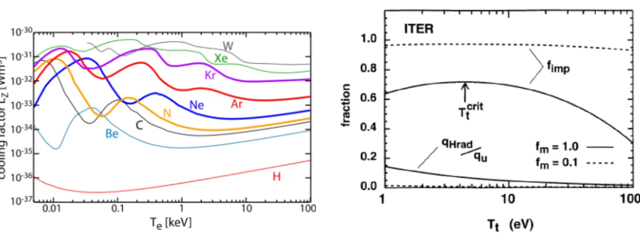
the recycling fuel are not sufficient to fall belowqmax⊥ then impurities need to be seeded. The choice of impurities or the mix of several impurities will depend on the expected temperature range, the achievable impurity density nZ andne. Their radiation then amounts toqimprad =nenZLz(ne,Te,τ)l, withlthe length segment over which the radiation is considered, withτ being the residence time of the charge states of the impurity at the location for whichneandTeare considered. A functional dependence of the cooling factorLZfor lim
τ→∞in coronal equilibrium for various seed and intrinsic impurities can be found in Fig. 1. The radiative impurity fraction,fradimp=q
imp rad
qu
FIG. 1. Cooling factor for a set of intrinsic and seeded impurities expected to be present in ITER or an FPP,
data from [11].
FIG. 2. Theoretically achievable radiative fraction in the SOL considering the M2PM as a function of the target temperature with Tet=Tit=Ttcalculated for an example
of ITER as detailed in [12] and adapted.
always lower than fdiss. While in experiments mixing radiative impurities has been used, willingly or unwillingly via intrinsic impurities, there is currently no clear statement or theory that allows to define the ideal mixing ratio of impurities as a function of discharge parameters. Interpretative numerical studies have just begun. It is therefore unclear to which extent such a mixture can be optimized for existing experimental devices and different impurities may simply replace each other when targeting only at maximizing fradimp. An extrapolation of how the entire plasma system reacts in a high DR of a FPP is thus extremely ambitious.
As stated by Krasheninnikov [13, 14] as well as by Stangeby [5, 6] the radiative losses of the hydrogenic fuel needs to be taken into consideration when considering power and particle fluxes to the divertor target plates. The radiation losses of recycling hydrogen is qrad
recy=qrecy−EpotΓt= (εion−Epot)Γt, where Epot=15.5eV is the potential energy for the ionization and dissociation of recycling molecules andεion is the loss of power to the electron heat channel, that as a function ofTt, may range from 15.5eV(zero net radiation) to∼100eV whenTtis around 1eV. The overall power reaching the target is now
qtk=quk−qdiss with qdiss=qimprad+qradrecy+q⊥+qrecom (1) with the last two terms expressing the perpendicular power loss due to transport processes across field lines (CX, diffusive and turbulent transport, as well as cross-field drifts) and volumetric recombination, for which the particle losses,Γrec, increase with decreasingTt.
Pitcher and Stangeby have in the past adressed the question of achievable power dissipation and in this context derived the achievable radiative fraction fradachieve,SOLin the SOL and divertor from the M2PM. It can be shown [5, 15] that
fradachieve,SOL=1−Kpu qu k (1−fmom) , with K= cs 4[γTt 1/2+Epot Tt 1/2 ] (2)
andγ being the sheath heat transmission coefficient andcs the ion sound speed. K is a weak function forTt> Ttcrit ∼5−10eV. Based on power balance considerations that includeqradrecy,qrecom and assuming no significant momentum losses it can be shown thatTt<Tcrit may lead to unstable or periodically oscillating divertor regimes [16, 17]. Figure 2 shows the theoretically achievable radiative fraction in the SOL, assuming no as well as a high pressure loss. The comparatively low radiative losses from recycling fuel are shown as well for the considered ITER case. Figure 2 shows that impurity radiation is required and that fradachieve,SOL may even decrease when Tt <Ttcrit. The achievable radiative fraction should decresse with upstream pressure, increase with increasing power flux density and lowqtkwill likely require impurity radiation as well as momentum removal, at least for reachingTtcrit. Depending on the device the SOL may not be capable to achieve fdissminand radiation from inside the separatrix may be required. However, following equation 2 increased radiation inside the separatrix may itself even reduce fradachieve,SOLas would a largerλq. In the context of detachment the notion ofpower starvationas a mechanism for achieving detachment is often referred to [5, 13, 14]. It can be shown that forTt<Ttcrit
Γt∝
quk−qdiss
εion
FIG. 3. Simulated ion current density jsatto a target
as a function of the ratio of the upstream pressure to the power available for recycling qrecycle(not to be confused
with the power radiated by the recycling fuel) shown for various PSOLand pure D plasmas, taken from [18].
FIG. 4. Ratio of target to static upstream electron pressure for experimental H-mode conditions on ASDEX Upgrade [19]. The continuos line represents a fit based on the data shown [5],
while the dashed curves shows the pressure loss according to the Self-Evald model, see also [12].
Without perpendicular transport or volume recombination Γt would saturate. The dissipation of power limits the achievableΓt and can lead to detachment, with Γt not being larger than the available power to sustain the ionization of the recycling neutrals. Figure 3 shows a numerical example of a simulated ion flux as a function of the quantities discussed so far in a simplified case without impurities. However, great care needs to be taken with equation 3 as this relationship and thus power starvation is only valid if momentum has been removed from the system to achieveTtcrit. Furthermore, in the region between the ionization volume and the target power is no more purely conducted and convection may contribute to limiting a rise ofΓtwith decreasingTt as thenΓt∝
fmom2 f
4/7
cond
1−fdiss ,
with 1−fcondthe fraction of convected power. We note that diffusive or turbulent perpendicular transport, which is always present under any condition will always redistribute momentum from one flux surface to a neighboring flux surface or even up to a PFC through the ion and the electron heat transport channels as well as via particle transport. Numerical simulations indicate that this channel may easily contribute to e.g. 30% of the total pressure loss. Therefore, perpendicular transport is likely playing a key role on the path to detachment.
2. ELEMENTARY PROCESSES, CURRENT UNCERTAINTIES AND RELATED PROGRESS OF
NUMERICAL SIMULATIONS
Due to the importance of momentum loss for detachment, processes that may contribute to fmomhave been inten-sively investigated since detachment was first observed [2, 20, 21]. However, a major drawback has been that for many years even the most sophisticated fluid transport codes used in the field were unable to numerically repro-duce the quantitative experimental observations in detached L- and H-mode plasmas in any of the experimental devices. Even qualitatively the codes lacked to describe important experimentally observed features and failed at lowTt [20], even though detachment as defined here could be achieved at low levels. Therefore, while the basic processes have been known, the detailed role of each processes and possible modifications of these through the combination and competition with each other were not understood. It appears that in the community incomplete interpretation of the role of CX processes had spread, where it was or is thought that impurity radiation removes power and CX processes then remove momentum from the SOL to PFCs and ultimately volume recombination sets in to incresse detachment, reducing pt further. Such an interpretation may have likely been facilitated by images similar to Fig. 4 where the comparison of the drop in electron pt occurs for Te<10eV. This by itself can be used as a criterion for the onset of detachment as such a behavior is observed in all reported experiments and simulations. The Self-Evald curve describes momentum loss via a CX processes that deposits the momentum directly on a PFC. The similarity of the functional dependence as a function ofTtimplied that CX plays a key role in removing momentum directly to PFCs. However, CX still plays a decisive role in reducing pt by redistribut-ing pressure to neighbourredistribut-ing field lines in a diffusive like process of short mean free paths of the neutrals in the direction perpendicular to the field as described in [13, 19], which may even lead to the electronpt being larger than its upstream value on flux surfces in the SOL, when pressure drops in the vicinity of the separatrix. As laid out by Stangeby CX plays a further important role in detachment, by facilitating volumetric particle recombina-tion at lowTe. When the plasma reaches values ofTefor which the rate coefficients of three-body and radiative
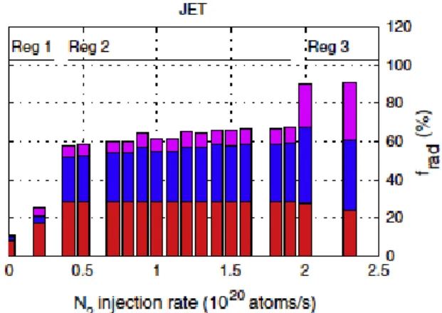
FIG. 5. Ratio of divertor radiation to radiation above the X-point as a function of fradimpfor JET N seeded H-mode
discharges [27].
FIG. 6. Contribution of the different regions of the computational domain to the total simulated radiation
for JET N2seeded L-mode conditions [28]. recombination become important, the ionization source will have moved upstream and a convective zone between the ionization source and the target will have formed. Free streaming ions will reach the target in a
characteris-ticdwell timeτdwell= nΓetL, with L the parallel distance between the ionization volume and the target plate. For
Tt sufficiently low, volume recombination can only become relevant ifτdwell>τrec, withτrecthe recombination time, being the inverse of the volumetric recombination rate.The CX processes reduce the speed of the plasma flow between the ionization volume and the target plate, thereby increasingτdwell, thus the volume recombination rate and therefore fmomand thus particle detachment. In numerical simulations often very lowTt can be achieved in front of the target plate. However, the poloidal/parallelTeprofile in many times does not reflect the experimen-tally expected one for high recycling or detached regimes as well as the simulated neutral pressure, being often missed by a factor 2-10. Consequently, numerically, volume recombination plays a less important role compared to experiment and a mismatch to spectroscopic hydrogenic line radiation should not be surprising [2, 21, 22]. That volume recombination is a key for being able to explain the experimentally observed strong reduction of pt has been highlighted in [5, 6, 13, 23] and references therein. Of the volumetric recombination processes it appears that three body recombination plays a more prominent role compared to molecular assisted recombination and experimental examples exist for quantifying its amount [24–26].
For ITER and an FPP impurity seeding will be mandatory to achieve sufficient power dissipation and radiation. Even inside the separatrix radiation will likely be necessary too, if, as e.g. estimated for a SN ITER like divertor geometry, fradachieve,SOL< fmindiss[2]. Experiments in the devices with metallic PFCs such as ASDEX Upgrade and JET, using various seed impurities, have shown, in conditions of maximum power dissipation, that a large frac-tion of the radiafrac-tion is emitted in the confined area. It appears that independent of the seeding species from a certain frad, dependent of the species, the contribution to the total radiation from the divertor diminishes and in some cases even the absolute amount of radiation from the divertor decreases with increased seeding. The case for highly radiative nitrogen seeded H-mode experiments is shown in Fig. 5. Even in numerical simulations of seeded L-mode plasmas at JET with increased impurity injection into the system the amount of radiation inside the core generally rises while from the inner and outer divertor volumes it either saturates or even decrease as seen in Fig. 6. To what extent this is in line quantitatively with the expected losses as discussed for equation 2 will need to be understood in more detail with the help of numerical simulations. The total radiation is measured through bolometric systems. At high frad a seemingly stable radiative regime can be obtained with pronounced radiation around the X-point. Detailed information on the distribution of the charge states contributing to the total radiation and experimental evidence of their transport and re-distribution in the SOL as a function of upstream and target conditions are lacking. Furthermore, while some estimate exists on the possible impurity screening by the pedestal, a quantifiable extrapolation of the impact of the cyclic behavior of ELMs is missing, see also [29] Measuring the impurity enrichment,Eimp, defined as the ratio of the impurity concentration,cnZ =nZ/ne, in the
divertor to that in the core, would help to better understand the connection of thecnZ along the SOL, their
radia-tive efficiency and it’s impact on fuel diluation and core radiation, which limitcnZ in the core plasma as outlined
in [11, 30]. This spectroscopic challenge still needs to be overcome, though major progress has been made in the case ofN2seeding [31]. Recent scalings by Reinke suggest that highBT devices are favorable for impurity radiation, for which the requiredcnZ∝B
0.88
T R1.33[32]. Figure 7 shows the evolution ofEimpfor a simulated, but unvalidated, H-mode case for ASDEX Upgrade as a function of the seeding level comparingN2andArseeding
FIG. 7. Divertor enrichment as a function of seeding level for N2and for Ar in a simulated ASDEX Upgrade H-mode
numerical case study [33].
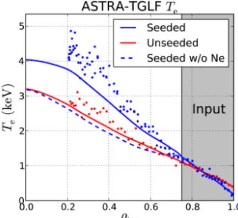
FIG. 8. Comparison of simulated and experimental core Te
profiles using ASTRA-TGLF for a JET Ne seeded discharge showing the effect of fuel dilution by Ne using as input
the experimental heating and radiation profiles [34].
FIG. 9. Sketch of the cross-field~Ex~B drift terms present in the divertor and the direction of the diffusive perpendicular
transport, adapted from [37].
FIG. 10. Density decay length as a function of divertor collisionality for ASDEX Upgrade
and JET L-mode plasmas from [38].
for the inner and outer divertors. While in the outer divertor, the most critical in terms of power load, forN2the enrichment decreases, by a factor 2, for Ar the enrichment first strongly increases and then drops with increasing seeding level, with the drop correlating with the transition to detachment at the inner divertor. An increase in radiation inside the spearatrix, however, does not necessarily imply a reduction of confinement as can be seen in discharges performed at JET [2, 35]. For Ne seeded discharges for which at high frad enhanced radiation in the inner divertor, the pedestal region and around the X-point can be observed, the confinement scaling H98y does not decrease despite a degradation of the pedestal pressure, since this is largely compensated by a steepening of the core profiles ofneandTe. This steepening is explained using ASTRA-TGLF simulations due to a stabilizing effect on the ITG modes by the dilution of the main ion density as shown in Fig. 8 [34]. Which impact seed im-purities have in highly radiative scenarios with strong X-point radiators and which correlation exists between the amount of detachment, the position of the ionization volumes, the impurity radiation and the closure of divertors will certainly be a major drive in the near future and activities have started inside the ITPA DIVSOL group. An important stepstone in modelling detachment has been the ability to recover the asymmetric behaviour of de-tachment when comparing the simulated inner and outer target to the dede-tachment observed in experiments. Here, neutral pressure measurements available across various poloidal locations in ASDEX Upgrade across the divertor was the pivot of uncovering the major discrepancies and to rectify these by eliminating or reducing the discrepancy of the latter down to a factor<2 for the best cases [2, 21, 28, 36]. While it was known that drift terms, as shown in Fig. 9 play a determining role in driving divertor asymmetries, even with only drift terms active it was not possible to obtain all of the experimentally observed features [20]. The interconnection of drift terms and turbulent per-pendicular transport has not been studied systematically due to the difficulty in operating numerical fluid transport codes with active drift terms and the related long convergence times. However, a key to success for simulations of ASDEX Upgrade has been the combination of an enhanced perpendicular transport at elevated divertor collision-ality,Λdiv, by adapting transport coefficients to reflect the increased upstream gradient lengths in the transition to detachment, with active drift terms. Numerical models of fluid transport codes assume that the perpendicular
par-FIG. 11. The maximum simulated nein the HFSHD region as
a function of heating power from [36].
FIG. 12. Comparing SOL profiles between the upstream and target location as modelled by COREDIV and SOLPS for the same fradimpby seeded N2from [39]. ticle transport isΓt=−D⊥∇n+n v⊥and the resulting heat flux thenq⊥=−χi∇Ti−χe∇Te+Γ⊥(Ti+Te) +qCX⊥ .
It was experimentally found that with increased divertor collisionality the density decay length, shown in Fig. 10, increases as does the particle flux. Not only was it possible to obtain an improved match with the overall ex-perimental data set, but even the exex-perimental dependencies of what is called the high field side high density, HFSHD, as a function of fueling, seeding and heating power, with the latter shown in Fig. 11, could be recovered numerically. A general rule under which conditions and with which value ofqkentering the HFSHD region this
can be sustained and therefore its relevance to next step devices are still open questions. Being able to model an H-mode discharge that features the HFSHD allowed to analyse in more detail the poloidal fueling profile, as experimental measurements of ionization sources and of the poloidal distribution of transport are missing. With perpendicular profiles between the separatrix and the pedestal top depending on transport and sources and the con-finement depending on the stability of the radial profiles, it was possible to link changes in the HFSHD to changes in confinement as a function of fueling, seeding and heating [40, 41]. Here, for ASDEX Upgrade, in the opera-tional space that had been investigated, the extent of the HFSHD modified the separatrix density, which otherwise correlates with the divertor neutral pressure through the recycling at the targets and the associatedΓt [42]. Such a modification ofnuby the HFSHD may not occur for all devices. In contrast recycling from the main chamber appears to impact the density profile inside the separatrix.
The assessment of the certainty with which we can apply our models to interpret experimental data and thus allow for a more general quantitative statement is starting to be looked at in the community and needs more attention in the future. In view of the complexity of numerical modeling with fluid transport codes, reduced models are being investigated on the basis of experimental data or numerical simulation results. However, they need to be applied and interpreted with great care as the example in Fig 12 shows. While the total radiation from impurity seeding simulated by the code COREDIV [43] is the same [39] as that of SOLPS5.0 [44], the underlying plasma profiles in the divertor are very different and so will be other aspects that may be extracted. However, in view of extrapolating to a FPP and being able to quickly asses the operational space such reduced numerical models as well as even simpler 1D or 0D scalings are the currently only feasible path. Validated reduced models of various levels of complexity may then be used in system codes to determine the performance of future devices and to specify their design [30, 45].
3. SUMMARY
The combination of experiments in devices with full metal PFCs, improved diagnostic capabilities and the use of numerical tools with a comprehensive set of physical models provided a major step forward in interpreting experimental data. A steady improvement lead to the identification of missing elements in the models, most prominently the interaction of the numerically expensive drift terms with enhanced far SOL transport. Thus our uncertainty about the highest achievable fdiss of the SOL narrows down to the largest extent to a quantitative obscurity about the nature of perpendicular SOL transport. While selected positive example cases of a successful numerical validation against experimental data exist they remain an exception. Most of all future simulations will need to systematically study the role of drift terms and turbulent perpendicular transport on divertor conditions and a parametrization of perpendicular transport needs to developed to be implemented into fluid transport codes. When comparing to experiments, uncertainties in results of the numerical model in comparison to the experimental data and a qualifier for the quality of the comparison need yet to be well defined. This may itself lead to a hierarchy of the experimental data to which successful comparison needs to be made as a function of the accuracy desired
[1] A. Kallenbach et al.Nuclear Fusion, 55:053026, 2015.
[2] M. Wischmeier et al. Journal of Nuclear Materials,463:22–29, 2015. [3] F. Reimold et al. Nucl. Fusion, 55:033004, 2015.
[4] A. S. Kukushkin et al. Journal of Nuclear Materials, 463:586, 2015. [5] P. C. Stangeby. Plasma Physics and Controlled Fusion, 60:044022, 2018.
[6] P. C. Stangeby.The plasma boundary of magnetic fusion devices. Institute of physics publishing, Bristol and Philadelphia, 2000.
[7] A. Loarte et al.Nucl. Fusion,47:S203, 2007. [8] T. Eich et al. Phys. Rev. Let., 107(215001), 2011.
[9] H. J. Sun et al. Plasma Phys. and Control. Fusion, 57:125011, 2015. [10] C. S. Chang et al.Nucl. Fusion,57:116023, 2017.
[11] T. Puetterich et al.ECA,39 E:P4.111, 2015. EPS Conference on Plasma Physics 2015. [12] C. S. Pitcher and P. C. Stangeby.Plasma Phys. Control. Fusion,39:779, 1997.
[13] S. I. Krasheninnikov et al.Physi. Plasmas,23:055602, 2016.
[14] S. I. Krasheninnikov and A. S. Kukushkin.J. Plasma Physics,83:155830501, 2017. [15] C. S. Pitcher et al. Journal of Nuclear Materials,241-243:1696, 1997.
[16] P. Manz et al.Nuclear Materials and Energy,12:1152, 2017.
[17] S. I. Krasheninnikov et al.Journal of Nuclear Materials,266-269:251, 1999. [18] A.A. Pshenov et al.Nuclear Materials and Energy,12:948, 2017.
[19] I. Paradela Perez et al. Nuclear Materials and Energy,12:181, 2017. [20] M. Wischmeier et al. Journal of Nuclear Materials,415:S523, 2011. [21] S. Wiesen et al.Nuclear Materials and Energy,12:3–17, 2017. [22] A. G. McLean et al.Journal Nuclear Materials, 463:533, 2015. [23] A. Kukushkin et al. Nuclear Materials and Energy, 12:984, 2017. [24] U. Fantz et al.Journal of Nuclear Materials,290-293:367, 2001. [25] C. Guillemaut et al. Nucl. Fusion, 54:093012, 2014.
[26] K. Verhaegh et al. Nuclear Materials and Energy,12:1112, 2017.
[27] A. Huber et al. ECA,38 F:P1.031, 2014. EPS Conference on Plasma Physics, Berlin, 2014. [28] L. Aho-Mantila et al.Journal of Nuclear Materials, page 546.
[29] R. Dux et al.Nuclear Materials and Energy,12:28, 2017. [30] M. Siccinio et al.Nucl. Fusion, 58:016032, 2018. [31] S. S. Hendersen et al. Nucl. Fusion, 58:016047, 2018. [32] M. L. Reinke. Nucl. Fusion, 57:034004, 2017.
[33] F. Hitzler et al.ECA,42 A:P2.1026, 2018. EPS Conference on Plasma Physics, Prague, 2018. [34] S. Gloeggler et al.ECA,42 A:P2.1025, 2018. EPS Conference on Plasma Physics, Prague, 2018. [35] M. Bernert et al. Nuclear Materials and Energy, 12:111, 2017.
[36] F. Reimold et al.Nuclear Materials and Energy,12:193–199, 2017. [37] A. Jaervinen et al. Nuclear Materials and Energy,12:1136, 2017. [38] D. Carralero et al. Physical Review Letters, 115:215002, 2015. [39] I. Ivanova-Stanik et al.Contrib. Plasma Phys., 56(6-8):760, 2016. [40] M. Dunne et al. Plasma Physics and Controlled Fusion, 59:014017, 2015. [41] E. Wolfrum et al.Nuclear Materials and Energy,12:18–27, 2017. [42] A. Kallenbach et al.Plasma Phys. Control. Fusion,60:045006, 2018. [43] R. Zagorski et al. Nuclear Fusion, 53:07030, 2013.
[44] R. Schneider et al.Contributions to Plasma Physics,40(3-4):328, 2000.
![FIG. 4. Ratio of target to static upstream electron pressure for experimental H-mode conditions on ASDEX Upgrade [19].](https://thumb-us.123doks.com/thumbv2/123dok_us/10033714.2902377/4.892.120.420.117.338/ratio-target-upstream-electron-pressure-experimental-conditions-upgrade.webp)
![FIG. 11. The maximum simulated n e in the HFSHD region as a function of heating power from [36].](https://thumb-us.123doks.com/thumbv2/123dok_us/10033714.2902377/7.892.144.780.109.275/fig-maximum-simulated-hfshd-region-function-heating-power.webp)
