Crosstalk Noise Aware System For WDM-Based
Optical Network on Chip
Ahmed Jedidi
Abstract—Network on chip (NoC) is presented as a promising solution to face off the growing up of the data exchange in the multiprocessor system-on-chip (MPSoC). However, the traditional NoC faces two main problems: the bandwidth and the energy consumption. To face off these problems, a new technology in MPSoC, namely, optical network-on-chip (ONoC) has been introduced which it uses the optical communication to guaranty a high performance in communication between cores. In addition, wavelength division multiplexing (WDM) is exploited in ONoC to reach a high rate of bandwidth. Nevertheless, the transparency nature of the ONoC components induce crosstalk noise to the optical signals, which it has a direct effect to the signal-to-noise ratio (SNR) then decrease the performance of the ONoC. In this paper, we proposed a new system to control these impairments in the network in order to detect and monitor crosstalk noise in WDM-based ONoC. Furthermore, the crosstalk monitoring system is a distributed hardware system designed and test with the different optical components according the various network topology used in ONoC. The register-transfer level (RTL) hardware design and implementation of this system can result in high reliability, scalability and efficiency with running time less than 20 ms.
Keywords—Optical Network on Chip, Wavelength Division Multiplexing, Crosstalk Noise, Detection Crosstalk, Waveguide, Optical Router.
I. INTRODUCTION
Nowadays, modern applications are very greedy in terms of memories, execution time, latency time etc. To satisfy these requirements, Multiprocessor system on chip (MPSoC) is presented as a promising solution in which it offers a large variety of resources as high numbers of processor cores, memories etc. However, MPSoC has to face serious challenges in terms of energy consumption, execution time, heat dissipa-tion and data flow [1]. Particularly, the data transfer between cores in MPSoC becomes the major challenge. Consequently, the function of the on-chip communication is essential to guarantee performance and scalability, which the network on chip (NoC) is an indispensable solution. With the growing up of data flow, the traditional network on chip (NoC) becomes a bottleneck for the scalability, the power consumption and the temperature dissipation in the MPSoC. The electrical interconnects are not able to achieve a high rate transmission and low power consumption, making it highly desirable to replace them [2]. In this context, finding a technology that offers a high bandwidth and a large scalability while keeping a low energy consumption and low temperature dissipation is the target, optical communication can be an ultimate solu-tion. The optical communication has a potential capacity of
A. Jedidi is with Faculty of National Engineering School, University of Sfax, Tunisia and Computer Engineering department, College of Engineering, Ahlia University, Bahrain (email: [email protected])
several tens of terabits/s per channel. Likewise, wavelength division multiplexing (WDM) consists of the multiplex optical signal in the same optical guide [1]. Consequently, the optical communication imposes as a promising solution for NoC. Therefore, optical network on chip (ONoC) is proposed to replace the traditional NoC [3]. Currently, several ONoCs employing WDM have been proposed in which mesh, torus and fat tree topologies [3], [4]. However, the optical devices and waveguides in ONoC provide transparency capabilities and new features allowing switching of traffic without any examination or modification of signals within the network. One of the typical problems with transparency is the fact that optical crosstalk is additive, and thus the aggregate effect of crosstalk over a whole ONoC may be more nefarious than a single point of crosstalk [5]. Moreover, optical crosstalk degrades the quality of signals and increases their Bit Error Rate (BER) performance. As a result, crosstalk is one of the major problems arising in ONoC and it is the first challenge facing the evolution of this technology in MPSoC. Consequently, detect, localize and monitor crosstalk in ONoC will be indispensable. In this paper, we propose a new system to detect, localize, evaluate and monitor the crosstalk noise in WDM-based ONoC. Principally, the proposed system has the capacity to detect and localize crosstalk noise in the optical components. A distributed hardware system has the responsi-bility to achieve these functions. Monitoring impairments in the whole network has running continuously to ensure and keep a healthy function of the MPSoC. In addition to this introductory section, this paper is organized as follows: the second section presents a brief overview of the related works, which it presents the least studies of the crosstalk noises in ONoC. While, the third section presents the inner architecture of the various devices in WDM-based ONoC in addition to the different network models. In addition, it illustrates the analytic model of the crosstalk noise induced in optical components. The fourth section describes the main key of the proposed system. It focus on the hardware designing and implementing the proposed system which consisting of three operations: detection, localization and monitoring the crosstalk noise in WDM-based ONoC. The fifth section provides the experi-mental results with the discussion in order to examine the feasibility of the proposed system. Finally, section six presents the conclusion and achievements; in addition, it covers the future works.
II. RELATEDWORKS
Optical network on chip provides a promising solution to increase the requirements in ultra-high bandwidth and lower
power consumption in the MPSoC. Accordingly, the progress of technology, nanophotonic waveguide and optical switch are presented in the chip, which they are the key components for ONoC [5]. In the literature review, many works propose an analytic model to evaluate crosstalk in ONoC. In particular, the evaluation of the crosstalk noise and SNR are achieved in the devices level and also for the network level. Fabrizio Gambini and al. proposed a photonic multi-micro-ring NoC, which its theoretical model based on the transfer matrix method, has been validated through experimental results in terms of transmission spectra [6]. Transmissions at 10 GB/s have been assessed in terms of BER for both single-wavelength and multi-wavelength configurations. The integrated NoC consists of 8 thermally tuned micro-rings coupled to a central ring, where the BER measurements show performance up to 109 at 10 Gb/s with limited crosstalk and penalty (below 0.5 dB) induced by an interfering transmission [6]. Many works which are deal with the crosstalk in the whole ONoC. Mainly, it is how the crosstalk noises affect the performance of the network. Particularly, these studies analyse and model, of the crosstalk progress in the different parts of the network, and present their effect to BER and SNR of the network. Mahdi and Al. systematically studied and compared the worst case as well as the average crosstalk noise and SNR for the three types of network topologies, mesh-based, folded-torus-based, and fat-tree-based ONoCs using WDM [3], [4]. These works present the analytic models for the crosstalk noise power and SNR particularly for the worst case. Furthermore, based on these studies the authors proposed crosstalk noise and loss analysis platform (CLAP) to analyse the crosstalk noise and SNR in WDM-based ONoCs [4]. As we presented above the research works in the optical network on a chip has limited to analyse and to model crosstalk noise in both optical components and the whole network. However, Edoardo Fusella and Alessandro Cilardo present different study in ONoC which they proposed a new mapping system for ONoC where it considers the direct effect of the crosstalk noise to the architecture of NoC [7]. Moreover, they propose a class of algorithms which map the application tasks onto a generic mesh-based ONoC architec-ture. This mapping class algorithm minimizes the worst-case crosstalk. As a result, the crosstalk noise can be expressively reduced by adopting the aware-crosstalk mapping system, thus allowing higher network scalability, and shows inspiring improvements over application-oblivious architectures [7], [8]. ZHE and al. presented a new method based on learning system to optimize the Thermal-Sensitive Power in optical network on chip [9]. Further, this approach is designed to found a routing system for the mesh- or torus-based optical NoCs in the presence of on-chip temperature variations and takes advantage of the Q-learning technique [9].
III. OPTICALNETWORKONCHIP
ONoC is proposed as an excellent solution to face off the growing demand of the data flow exchange in MPSoC. Further, the higher performance can be reached by using the WDM technology, which it has been rapidly gaining acceptance as an important means employed for taking advantage of the
enormous bandwidth in optical communication. This section presents the different structures of the optical components in WDM-based ONoC. In addition, it depicts the different network models used in WDM-based ONoC. Finally, crosstalk noise analytic models present in components and network levels.
A. Optical components in ONoC
Waveguides and micro-resonator (MRs) are two basic opti-cal elements and extensively used to construct fundamental optical switching elements and optical routers. Particularly, two types of optical switches are presented: the parallel switch-ing element (PSE) and the crossswitch-ing switchswitch-ing element (CSE). These elements are 1 x 2 optical switching based on MRs and waveguide crossing [10]. Furthermore, the inner structure of PSE and CSE shown in figure1. Indeed, the first one composes by two parallel waveguides and specific numbers of MRs according the number of the wavelengths used in the proposed system. The second one has the same structure, as the PSE with one difference is to integrate a waveguide crossing in one of the side of the CSE [7].
MR1 MRn MR1 MR1 . . . . . . Drop Add Input Through λn λn OFF State MR1 MRw (a) MR1 . . . MRn . . . MRw Drop Add Input Through λn λn ON State (b)
Fig. 1. Optical Switch elements:(a)PSE in OFF state, (b)CSE in ON state
Currently, the silicon photonics technology proposes many types of switches and routers for the WDM-based ONoC. In general, the optical router has five inputs/outputsports, the first four ports (West, East, North and South) used to connect with the different elements of network and the fifth port serves to inject/eject optical signal to processor core. Figure 2 presents the basic structure of the 5 x 5 optical router, which most of these routers using CSE and PSE in his inner architecture. In literature reviews, most of works proposed essential two types of optical router: the optical turnaround router (OTAR) and Crux router (Cr). First, figure 3 shows the structure of the OTAR router as proposed by [11]. OTAR is an 4x4 optical router adopting the turnaround routing algorithm. It consists of four optical switches each one contains W RMs
5 x 5
Optical
router
East
West
North
South
m
p
iFig. 2. The main structure of the 5X5 optical router
i.e. W is the number of wavelength travelling through the ONoC. The OTAR router has four bi-directional ports, which are called upper-right, upper-left, lower-left and lower-right. We assigned port 1 for the right, port 2 for the upper-left and port 3, 4 for lower-upper-left and lower-right respectively.
MR1 Upper-Right λ1λ2 MR1 MR1 MRMR12 MR1 MR1 MRMR12 MR1 MR2 MR1 MR1 MRMR12 λ1λ2 Upper-Left λ1λ2 λ1λ2 L owe r-R ight λ1λ2 λ1λ2 λ1λ2 λ1λ2 Lower-Left
Fig. 3. The structure of the 44 OTAR router for WDM-based ONoCs using W optical wavelengths
Considering the scenario presented in figure 3, the optical signal of the wavelength λ1(red colour) is selected to be
switching from upper-right to upper-left. First, the signal λ1
enter form upper-right, when it reaches the first M R1the
status of this one is OFF then λ1 continues its route in
the same waveguide until the second M R1. The status of
the second M R1 is ON, so the signal λ1 switch from the
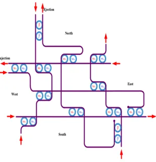
current waveguide to the other and continues its route to reach the upper-left out port. Second, figure 4 describes the inner structure of 5x5 Crux router, which it has five input and five output ports (West, East, Nort, South and Injection /Ejection). In addition, Cr composed by eight CSE and four PSE. It used the dimension-ordered routing algorithm, also known as the XY routing algorithm. Mr1 Mrw Mr1 Mrw Mr1 Mrw Mr1 Mrw Mr1 Mrw Mr 1 Mr w Mr1 Mrw Mr1 Mrw Mr1 Mrw Mr1 Mrw Mr1 Mrw Mr 1 Mr w North East West Ejection Injection South
Fig. 4. The inner structure of the 55 Crux router for WDM-based ONoCs using W optical wavelengths.
B. Network models
Typically, in ONoC, they have three network models: mesh, torus and fat-tree topologies [12], [13]. For the mesh and torus topologies, they used 5x5 Crux optical routers other hand, the fat-tree network used OTAR routers. Figure 5 shows the mesh and torus topologies respectively. To connect M x N processor cores they use M x N crux routers. The XY routing algorithm used to establish paths between cores in mesh and torus networks. Furthermore, the worst-case to establish routes used XY routing algorithm requires going through M+N-2 hope for both topologies.
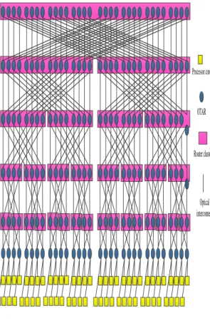
Based on the OTAR router, [11] proposed the fat-tree-based ONoC (FONoC) as shown in figure 6. The floorplan of the FONoC allows connecting multiple MPSoCs with low cost and save energy consumption. To connect k processor cores we required l-level in the fat tree network noted FONoC(l,k), wherel= log2(k)−1. There k processor cores at level 0 and
k/2 OTARs for each other levels. However, the total number of OTARs is:
l∗k/2 = (log2(k)−1)∗k/2 (1)
In FONoC, usually, we adopt the traditional turnaround routing algorithm (TRA), but [11] proposes to optimize this algorithm to improve energy efficiency and called energy-efficient turnaround routing (EETAR). EETAR uses an adap-tive and distributed routing algorithm in objecadap-tive to establish
Processor core
Optical router
Waveguide
(a) (b)
Fig. 5. The ONoC network topologies: (a) Mesh , (b) Torus
a route between source core and destination core, which improves the energy efficiency [14].
Processor core OTAR Router cluster Optical interconnect Level 0 Level 1 Level 2 Level 3 Level 4 Level 5 Level 6
Fig. 6. The fat-tree-based optical NoC
C. Crosstalk noise in ONoC
Optical crosstalk noise arise as crossing two optical signals reach the same PSE or CSE in the router simultaneously [15], [16]. As a result, the crosstalk noise degrades the quality of signals, increasing their BER and the SNR is decreased [17]. On these grounds model and analyse the optical crosstalk noise should be a high priority for the researches. In fact, both
forms of optical crosstalk noise can occur in ONOC routers: inter-channel crosstalk and intra-channel crosstalk [6], [18]. The both the intra-channel and inter-channel crosstalk will be treated as a priority in this work and we call it crosstalk noise. [3], [19] presented an analytical model of the worst-case crosstalk noise and SNR for the different optical devices and network topologies. Furthermore, the crosstalk noise power
nλn
i,j added to the considered optical signalλn traveling from the ith input port toward the jth output port in the optical router is present in Eq2. For more details, the complete studies of the analytic model for the different optical devices are presented in [3], [19]. nλni,j = portnum X m=0 ((Pλn m ∗L λn m,j∗X λn i,j,m+ w X e=1,e6=n (Pλn m L λn m,jY e i,j,m)) (2) Where,Xλn
i,j,m is presented as the crosstalk noise coefcient introduced by the interfering optical signals of the wavelength
λn enters from the input port m through the waveguide crossing the corresponding MRs. further,Yi,j,me is the crosstalk noise coefcient added by the interfering optical signal through the rest of MRs and MRe.Lλnm,j is the power supplement loss from themthinput port to thejthoutput port. Finally,Pλn
m is the power of the interfering optical signal at the input port m. Otherwise, in general the evaluation of the SNR of the optical signal from source processor core to the destination core can be defined as the ratio of the signal power to the power of the crosstalk noise, as depict by Eq3 in which PSis the optical signal power and the PN is the crosstalk noise power [4]. Particularly, [19] present the SNR for the mesh topology, [6] describe the SNR for the torus network and [20] propose the SNR evaluation for the fat-tree network.
SN R= 10 log(PS/PN) (3)
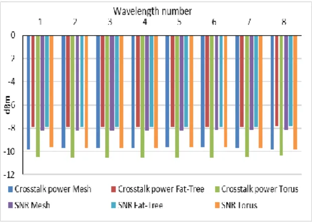
Using the CLAP simulator [6], figure 7 presents the crosstalk power and the SNR for the different network topolo-gies according the wavelength number. It is assumed that the injection laser power P is equal to 0 dBm [3]. We notice that the SNR increase with the number of wavelength. In addition, the effect of the crosstalk noise affect all types of topologies without exception. As a result, crosstalk noise presents a really menace for the performance of the ONoC.
IV. CROSSTALKAWARESYSTEM
The optical crosstalk noise introduced by the optical com-ponents based on the transparency characteristics of these devices, which is a serious barrier for the development of the ONoC. Furthermore, the crosstalk noise is the first responsible to limited the reliability, the scalability and the performance of the MPSoC. Consequently, find a system to assist and monitor the crosstalk noise in the different levels in depth and breadth of the ONoC has a high priority. The Crosstalk Aware System (CAS) proposes a performed system to detect and localize the crosstalk noises in the optical devices then monitor and assist these impairments and be aware about the different damages in the network level. The mean idea of CAS
Fig. 7. Crosstalk noise power and SNR as function the number of wavelengths
is to detect and monitor the different crosstalk noises occurred in the ONoC with a high accuracy. In this way, the CAS has a mission to aware and avoid the different impairments that cause limitation of the ONoC performance. To complete this mission CAS pass through two principal steps. First, the proposed system should detects and localizes the crosstalk noise in the optical components level which Device Crosstalk Detection (DCD) is the responsible. Second CAS monitors and assists the impairments in the network level according the Monitor and Assist Crosstalk system (MAC). The proposed CAS should satisfies these different features:
• Accuracy: the detection and the evaluation of the crosstalk noise require a high precision.
• Scalability: the CAS should has the capability to function with the same performance for the ONoC scale size. • Efficiency: the performance of the CAS should be running
in real time execution.
A. Device crosstalk detection
Optical communication offers a high data rate bandwidth, particularly when we appalling the WDM technology. The major problem of the optical communication is the trans-parency of the optical devices that is the source of the crosstalk noise. The crosstalk noise in both types Intra-channel and Inter-channel are introduced inside the optical devices mostly with the presence of various optical signals that had different wavelengths. Consequently, the detection of the crosstalk noises should to be done in the optical device level in which we propose Device Crosstalk Detection (DCD). The DCD is a hardware component; his mission is to detect the crosstalk noise introduced by crossing signals inside the optical router. The main idea of the DCD is to check the different optical signals passed through optical devices, and then begin the process of detection and evaluation of the crosstalk noise as shown in figure 8. The impact of the Crosstalk noise to the optical signal depends with the crosstalk power level, in this way detection crosstalk is not sufficient and the evaluation of the occurred impairment should to be done.
The inner architecture of DCD depict in figure 9 First, DCD splits the different optical signals from the input/output
East West North South
DCD
5 x 5 Optical routerFig. 8. The Device Crosstalk Detection (DCD) in optical router
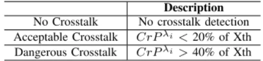
of the optical router, which the complexity of this operation depends, from the number of wavelengths used in the network. Furthermore, it using an appropriate MRs to switch the desired wavelength λi, and a photodetector module is employed to convert the optical signals in digital information. The crosstalk detection process initiate using a sequential comparison steps. If a crosstalk is detected the system of evaluation and classifi-cation will be launched. The evaluation of the crosstalk noise is based on his power, which DCD measures the crosstalk power and according this value it establishes a classification process as shown in Table I. Further, the crosstalk power is compared to a crosstalk thresholdXthin which the user fixes it. MR1 MRn MRw OPw OPn OP1 Downstream (split signals) MRw MRn MR1 OP1 OPn OPw Upstream (split signals)
Device Crosstalk Detection (DCD)
. . .
. . .
= = = Shift process Shift process Shift process Shift process Shift process Shift processMonitor and Assist Crosstalk (MAC)
Fig. 9. The inner structure of the Crosstalk Detection (DCD)
The total crosstalk noise power in the Router N for the optical signalλi is presented by:
WhichCrPwaveguideλi is the crosstalk power introduced by the waveguide andCrPλi
nodeis the crosstalk power injected by the router.
The classification of the crosstalk noise is essential to monitor and assist the impact of the impairments in the whole route for the optical signal. We notice independent for the types of optical routers or switchers the DCD is employed correctly because it using the optical signals on the input-output ports.
TABLE I
CLASSIFICATION OF THE CROSSTALK NOISE TYPES
Description
No Crosstalk No crosstalk detection
Acceptable Crosstalk CrPλi<20% of Xth
Dangerous Crosstalk CrPλi>40% of Xth
B. Monitor and assist crosstalk system
The dangerous aspect of the crosstalk noise is not because it arises in single point and affect the appropriate signal but it propagates and affects the different optical signals crossing this signal through all optical routers. The additive nature of the crosstalk noise makes it this impairments the first problems and to improve the ONoC performance. As a result, monitor and assist the crosstalk noise for the whole network is modera-tor, which we propose a general system to Monitor and Assist Crosstalk (MAC). MAC using a distributed number of DCDs which are employed according the appropriate architecture of the network. Furthermore, the type of ONoC architecture forced the numbers and the disposition of these DCDs. First, for the fat-tree-based network MAC uses DCD placed between two OTAR routes in the same level as shown in figure 10. Moreover, the number of DCD placed in fat tree network is calculated in Eq.5. Particularly,k/4of DCD are employed for each level of the network.
DCDsnumber= (log2(k) + 1)∗k/4 (5)
Where, k is the number of the cores processor.
Each DCD detects and evaluates the different optical signals pass through two OTARs and forwards the outcomes for the MAC. To insure the correct process of the different wave-lengths, we inject signals with the same power 0 dBm. Further, the split signals process consists to duplicate signals from input / output of the router in objective to conserve the same amount of the power signal. Second, the mesh architecture using M number of DCDs blocs, which M is the number of routers as shown in figure 11. Additionally, each DCD is placed beside each optical router which controls the different optical signals passing through this device. DCD manages the different input/output ports of the optical component that generates the outcomes forward to the MAC. For the torus network has the same distribution of DCDs as mesh network. MAC uses the different outcomes of Z number of the DCD blocs, which distributed according the network architecture types. These DCD outcomes are the crosstalk detection and the crosstalk evaluation if exist. The complexity and the feasibility
7 8 11 12 15 16
3 4
1 2 5 6 9 10 13 14
Processor
cores Optical Router
Crosstalk Detection Module
Optical Split Signal
Fig. 10. Device Crosstalk Detection in FONoC
of CAS depend for the size of the network as shown in figure 12. The number of DCDs increase with the number of processor cores particular for the Fat-tree based network, which has the high number, compare to the others topologies (mesh and torus).
The monitoring and assisting of the crosstalk noises in the whole ONoC begin by collecting the different outcomes from the various DCDs. Furthermore, MAC assists the optical signal from the source core to the destination core based on the path description that signal taken and the diverse outcomes information from the DCDs composing this route. Particularly, MAC examines the crosstalk noise in the optical signal λi along the path if it exist and generates an appropriate alarm according the danger that introducing by this impairment. The algorithm 1 presents the operation of the MAC. When a Processor core m (source: SCm) requests to communicate with the processor core n (destination: DCn)SCm=⇒DCn, the MAC begin to collect the different crosstalk values from DCDs for the appropriate wavelengthλs. Second, it examines all these information to detect and localize the source of this impairment. Finally, MAC generates alarms according the danger causing by the crosstalk noise to network. Besides, the operation of the MAC uses the following parameters as inputs: • The path definition between core source and core
desti-nation PSCm⇔DCn.
Processor core
Optical router
Waveguide
Device Crosstalk
Detection
Fig. 11. Device Crosstalk Detection in mesh topology
0 500 1000 1500 2000 2500 16 32 64 128 256 512 1024 N u m b e r o f D C D s
Number of cores processor
Mesh Fat-tree Torus
Fig. 12. Complexity of the Crosstalk Aware System
• Optical routerORi,j⊆PSCm⇔DCn.
• Crosstalk valueCrvi,j
For a specific optical signal λs assigned to connect SCm to DCn, the MAC collects the different crosstalk values from the various DCDs which defines the Path PSCm⇔DCn. Then it examines theses values to localize the crosstalk noise and to generate alarms. Furthermore, a crosstalk threshold are defined to manage the performance of the CAS. Two levels of the crosstalk thresholds are presented to monitor and assist the crosstalk noise in his propagation to the overall network.
Algorithm 1 Monitor and Assist Crosstalk System
1: Input: Source Core m(SCm),Destination Core n(DCn),Wavelength λs, W number of wavelength in ONoC,Path SCm ⇔ DCnPSCm⇔DCn, Crosstalk valueCrv(i, j), optical routerORi,j⊆PSCm⇔DCn
2: Output: localize crosstalk and generate alarms
3: form, n←1toM M do. M x M are the total number of processor cores
4: SCm←SC(m)
5: DCn←DC(n)
6: P ath←PSCm⇔DCn . path betweenSCmandDCn
7: fori, j←1 toZ, Y ⊆P athdo. Z , Y are the total
number of optical router define the pathPSCm⇔DCn
8: ifCrvi,j(λs)> Xmaxth then
9: Alarm(s)←Highlevel
10: Location(s)←ORi,j
11: for t←1 toW ⊆ORi,j do . W are the number of wavelength passed through theORi,j
12: if Crvi,j(λt)> Xmaxth then
13: Alarm(t)←Highlevel
14: Location(t)←ORi,j
15: else if Xminth < Crvi,j(λt)< Xmaxth then
16: Alarm(t)←Lowlevel
17: Location(t)←ORi,j
18: else
19: Alarm(t)←Saf elevel
20: end if
21: end for
22: else ifXth
min< Crvi,j(λs)< Xmaxth then
23: Alarm(s)←Lowlevel
24: Location(s)←ORi,j
25: CrT(λs) =CrT(λs) +Crvi,j(λs)
26: else
27: Alarm(s)←Saf elevel
28: end if
29: end for
30: if CrT(λs)> Xminth andORi,j⊆P ath
1/4
upper then
31: Alarm(s)←Highlevel
32: Location(s)←ORi,j
33: else if CrT(λs) < Xminth andORi,j ⊆ P ath
1/2 upper then 34: Alarm(s)←Lowlevel 35: Location(s)←ORi,j 36: else 37: Alarm(s)←Highlevel 38: end if 39: end for First, theXth
maxpresents the maximum power value allowed to the crosstalk noise that can reach. Second, the of crosstalk noise power is acceptable but need to be monitor noted by
Xminth . In the case, when the crosstalk noise exceeds the
Xmaxth a high priority alarm is generated with the ID of the corresponding optical router as the location of the impairment. In addition, the MAC activates the process of examination of the crosstalk noises in the different optical signals passing through this optical router. This operation investigates the
TABLE II IMPAIRMENTSALARMS
Alarms Definition
High level Detect one or more impairments. The crosstalk noise
power has a critical level that direct damage the signals then the network performance.
Low Level Detect one or more impairments. The crosstalk noise
power has an acceptable level but need to be super-vised. In addition, it damages the signals but not has a serious effect to the network performance.
Safe level No Crosstalk detected
effect of the crosstalk noise to the others wavelengths in objective to be aware about the different crosstalk noises inserted to the others optical signals in this level of the network. Moreover, three alarms types defined according the level of the crosstalk noise power add to the corresponding optical signal. Table II defines the three alarms types.
Otherwise, if the crosstalk noise power are betweenXminth
and—Xmaxth a low priority level of alarm is created with the location of the router and an accumulation of crosstalk power calculated CrT(λs)for the according wavelength λs. The accumulate crosstalk noiseCrT(λs)used to monitor the optical signalλsin association with the position of the optical routerORi,j.
V. RESULTS ANDDISCUSSION
In this section, we test, evaluate and discuss the correctness function, features and the feasibility of the crosstalk aware system CAS. Furthermore, we define various crosstalk noise scenarios to test the correctness function of our system in which we insert crosstalk noise with different power values with in various wavelengths. Table III describes the various scenarios applied, where the first one presents a dangerous crosstalk noise introduced in the last quarter of the network. In addition, the second scenario injects two different types of crosstalk noise one in λ1 with power value is less than
Xth
min placed in the beginning of the path and the other one in λ2 with the same power value placed in the end of the
path. Moreover, we create an input test file in which we insert the different values in our system. Beside, we recover the different outputs and compare with the test file. ModelSim PE used to simulate the different scenarios. Figure 13 depicts the functional simulation and the result of the different scenarios in which it shows the various alarms generated according the features of the each scenario. According the functional sim-ulation it is clear that CAS running with a high performance and correctness operation.
Figure 14 shows the cost, the complexity and the scalability of CAS. We evaluate these parameters with the surface of im-plementation in FPGA. Indeed, we calculate the total number of the lookup table (LUT) with the simulation tool (Project Navigator of Xilinx and ModelSim). Moreover, LUT reflects the occupation area of CAS modules in a chip. In this context, we select STARTER Kit of Xilinx to design and implement our system. Particularly we use SPARTAN-3E. Particularly, Fig. 14 presents the features of the CAS according the number of
TABLE III
CROSSTALK NOISESSCENARIOS SIMULATION
Definition Alarms generated
Scenario 1 The crosstalk noise (λ1) has a
power value great thanXth
max
High Level alarm plus the location of the source router of the impairment Scenario 2
• First crosstalk in λ1 with
power value is less than
Xth
min placed in the
begin-ning of the path
• Second crosstalk inλ2 with
power value is less than
Xth
min placed in the end of
the path
Two alarms are generated:
• high level for theλ1
signal
• safe level for theλ2
signal
Scenario 3 Introduces two crosstalk noises
which the power between Xth
min
andXth
maxthe firstλ1 in the
be-ginning of the path and the second
λ2in the end of the path.
High level Alarms are generated for the first one crosstalk noises and a low level alarm for the second one.
Scenario 4 Inserts crosstalk noise with a power
value great thanXth
maxin the
be-ginning of the path.
High level alarm gener-ated
wavelength, the number of processor cores used according the various network topologies. We note that the total number of
Crosstalk_noise 0 1 2 3 No crosstalk
less than Xmin
between Xmin and Xmax
more than Xmax
Poisiton_noise
1 3
begin of the path end of the path
Alarm 0 1 2 3 No alarm Safe level Low level High level
Fig. 13. Simulation Functional of CAS with various Crosstalk noises
LUTs increases exponentially as the number of processor cores scales. Indeed, this evolution explained by the increase in the number of DCD according the size of the network. In addition, we remark that the execution time increases smoothly as a function the number of cores. In particular, the average of the exactions time is around 20 microseconds. As a result, CAS reaches a real-time function with a high scalability. Indeed, with a network, having 2048 processor cores, CAS need less than 4000 LUTs and this value is 0.01% of the size of the chip.
VI. CONCLUSION
Network on Chip is a great solution to solve the problem of communication between cores in MPSoC, but is limited by the
0 5 10 15 20 25 30 0 500 1000 1500 2000 2500 3000 3500 4000 16 32 64 128 256 512 1024 E x e c u ti o n T im e (m s ) N u m b e r o f L U T s
Number of processor cores
Mesh Fat-Tree Torus Mesh Fat-Tree Torus
Fig. 14. Time execution and Area occupation of the MAC
increased number of cores implemented in one chip. Beside, optical communication presents itself as a trend solution for this technology. Indeed, Optical Network on Chip is a promotional solution that solves the problem of high rate of data exchange between cores with less energy consumption. Nevertheless, ONoC is affected by crosstalk noise, which is a major problem that hinders the achievement and maintenance of high performance. Consequently, this paper presented a whole solution to monitor the crosstalk noise in ONoC. First, we described the various optical devices and network topol-ogy used in ONoC. In addition, analytical crosstalk models presented for each device. Second, we proposed a new system to detect and monitor crosstalk noise in ONoC. The crosstalk aware system (CAS) is based on the collection of the different information from disturbed devices DCD located in the whole network. Finally, we implemented and simulated our system to evaluate performance, scalability and real-time function. The results have demonstrated that our system offers a high scalability with a low rate of occupation in the areas of the chip as well as a real-time function with 20 microseconds as execution time.
REFERENCES
[1] Bonetto. E, Chiaraviglio. L, Cuda. D, Gavilanes. G.A., and Neri. F, Optical technologies can improve the energy efficiency of networks, Proceedings of the 35th European Conference on Optical Communica-tion. , 2009, Vienna, Austria, 14
[2] Cianchetti. M.J, Kerekes. J.C, and Albonesi. D.H, Phastlane: A rapid transit optical routing network, JProceedings of the 36th International Symposium on Computer Architecture, 441450, 2009,Austin, TX, USA [3] Nikdast. M, Xu. J, Duong. L.H.K, Xiaowen. W, Xuan. W, Zhehui. W, Zhe. W, Peng. Y, Yaoyao. Y, and Qinfen. H,Crosstalk Noise in WDM-based Optical Networks-on-Chip: a Formal Study and Comparison,IEEE
Transactions on Very Large Scale Integration Systems, vol.23, no.11, 2552-2565. ,2015
[4] Nikdast. M, Jiang. X, Xiaowen. W, Wei. Z, Yaoyao. Y, Xuan. W, Zhehui. W, and Zhe. W ,Systematic analysis of crosstalk noise in folded-torus based optical networks-on-chip,IEEE Transactions on Computer-Aided Design of Integrated Circuits and Systems, vol. 33, no. 3, 437450.,2014 [5] Yiyuan. X, Jiang. X, Jianguo. Z, Zhengmao. W, and Guangqiong. X,Crosstalk Noise Analysis and Optimization in 5x5 Hitless Silicon-Based Optical Router for Optical Networks-on-Chip (ONoC),Journal of Lightwave Technology, Vol 30, No.1, 198-203., 2012
[6] Fabrizio. G, Stefano. F, Paolo. P, Nicola. A, and Isabella. C,BER evaluation of a low-crosstalk silicon integrated multi-microring network-on-chip,Optics express journal, Vol. 23, Issue 13, 17169-17178.,2015 [7] Edoardo. F, and Alesandro. C, SCrosstalk-Aware Automated Mapping
for Optical Networks-on-Chip, ACM Transactions on Embedded Com-puting Systems, Vol. 16, No. 1, Article 16, 1-26., 2016
[8] Xie. Y, Nikdast. M, Jiang. X, Wei. Z, Qi. L, Xiaowen. W, Yaoyao. Y, and Xuan. W,Crosstalk noise and bit error rate analysis for optical networkonchip,Proceedings of the 47th Design Automation Conference on -DAC ’10, 657660. ,2010, Anaheim, California,
[9] Zhe. Z, and YAOYAO. Y, Learning-Based Thermal-Sensitive Power Optimization Approach for Optical NoCs, CM Journal on Emerging Technologies in Computing Systems (JETC) Volume 14 Issue 2, N21, 2018
[10] Ding. W, Tang. D, Liu. Y, Chen. L, and Sun. X,,Compact and low crosstalk waveguide crossing using impedance matched metamaterial, Applied Physics. Letters, vol. 96, 111114-1111114-3,2010
[11] Gu. H, Xu. J, and Zhang. W , A low-power fat tree-based optical network-on-chip for multiprocessor system-on-chip,Proceedings of the Design, Automation and Test in Europe Conference and Exhibition , 3-8,2009, Nice, France
[12] Luan. H.K, Zhehui. W, Nikdast. M, Jiang. X, Peng. Y, Zhifei. W, Zhe. W, Rafael. K.V.M, Haoran. L, Xuan. W, Sbastien. L.B, and Yvain. T,Coherent and Incoherent Crosstalk Noise Analyses in Inter/Intra-chip Optical Interconnection Networks,IEEE Transactions on Very Large Scale Integration Systems, vol. 24, no. 7, 2475-2487,2016
[13] Wang. Z, Xu. J, Wu. X, Ye. Y, Zhang. W, Nikdast. M, Wang. X, and Zhe. W, Floorplan optimization of fat-tree-based networks-on-chip for chip multiprocessors, IEEE Transactions on Computers, vol.63, no. 6, 14461459., 2014
[14] Zhang. L, Regentova. E.E, and Tan. X, Floorplan optimization of fat-tree-based networks-on-chip for chip multiprocessors, Proceeding of the Symposium on Photonics and Optoelectronics, 14., 2011 ,Wuhan, China [15] Chan. J, Hendry. G, Bergman. K, and Carloni. L.P , Physical-layer mod-elling and system-level design of chip-scale photonic interconnection networks, IEEE Trans. Comput.-Aided Design Integr. Circuits Systems, vol. 30, no. 10, 15071520, 2011
[16] Jedidi. A, Regeb. R, and Abid. M , Detection and localization of crosstalk in an all-optical network, Journal of optics, volume 13, number1, Publisher IOP Science., 2011
[17] Duong. L.H.K, Nikdast. M, Sebastien. L.B, Xu. J, Wu. X, Wang. Z, and Yang. P, A case study of signal-to-noise ratio in ring based optical networks-on-chip, IEEE Des. Test Comput, vol. 31, no. 5, 5565, 2014 [18] Dong. P, Qian. W, Liao. S, Liang. H, Kung. C.C, Feng. N.N, and
Shafi. R, Low loss silicon waveguides for application of optical inter-connects,Proceeding of the IEEE Photonics Society Summer Topical Meeting Series. 191192.,2010 , Playa del Carmen, Mexico
[19] Xie. Y, Nikdast. M, Xu. J, Wu. X, Zhang. W, Ye. Y, Wang. X, Wang. Z, and Liu. W, Formal worst-case analysis of crosstalk noise in mesh-based optical networks-on-chip,IEEE Trans. Very Large Scale Integr. (VLSI) Syst., vol. 21, no. 10, 18231836. ,2013
[20] Nikdast. M, Luan. H.K.D, Xiaowen. W, Zhehui. W, Xuan. W, and Zhe. W, Fat-Tree-Based Optical Interconnection Networks Under Crosstalk Noise Constraint, IEEE Transactions on Very Large Scale Integration (VLSI) Systems, Volume: 23, Issue:1, 156 - 169,2015