Notice
Note that when converting this document from its original format to a
.pdf file, some minor font and format changes may occur. When
viewing and printing this document, we cannot guarantee that your
specific PC or printer will support all of the fonts or graphics.
Therefore, when you view the document, fonts may be substituted and
your individual printer may not have the capability to print the
NEC Unified Solutions, Inc. has prepared this document for use by its employees and customers. The information contained herein is the property of NEC Unified Solutions, Inc. and shall not be reproduced without prior written approval of NEC Unified Solutions, Inc.
Dterm is a registered trademark of NEC Corporation and Electra Elite is a registered trademark of NEC America, Inc. Windows is a registered trademark of Microsoft Corporation. AT&T is a registered trademark of American Telephone and Telegraph Company. Lucent Technologies is a trademark or service mark of Lucent Technologies Inc. Nortel Networks and the Nortel Networks logo are trademarks of Nortel Networks.
Copyright 2006
NEC Infrontia, Inc. 6535 N. State Highway 161
Irving, TX 75039-2402
___________________________________________________________________________________
Chapter 1
Introduction
Section 1 Electra Elite IPK II IP ... 1-1 Section 2 Voice Over IP ... 1-1
Chapter 2
General IP Configuration
Section 1 Introduction ... 2-1 Section 2 Network Addressing Overview ... 2-1 2.1 IP Address ... 2-1 2.2 Subnet Mask ... 2-2 2.3 DHCP ... 2-2
Section 3 Configuration Examples ... 2-3 3.1 Example Configuration 1 - Existing Network with
Static Addressing ... 2-3 3.2 Example Configuration 2 - New Network with
Dynamic Addressing ... 2-5
Section 4 Testing the Electra Elite IPK II Network Connection ... 2-9
Chapter 3
IP Extensions
Section 1 Introduction ... 3-1 Section 2 IP to TDM Conversion ... 3-2 2.1 IP Telephones (ITH) ... 3-2 2.2 Electra Elite IPK Multiline Telephone (DTH) with IP Adapter ... 3-3
3.2 Operation During Power Failure ... 3-5
Section 4 LAN Connection ... 3-6 Section 5 Providing Power ... 3-7 5.1 Local Power ... 3-7 5.2 Powered Patch Panel ... 3-7 5.3 Power Over Ethernet (PoE) ... 3-7
Section 6 DIP Switch Settings ... 3-8 Section 7 Peer-to-Peer ... 3-9 Section 8 Programming ... 3-9 8.1 System Tones and Ring Tones ... 3-10 8.2 Music on Hold ... 3-10
Section 9 Configuration Examples ... 3-10 9.1 Example Configuration 1 - Static IP Addressing, One LAN ... 3-11 9.2 Example Configuration 2 - Dynamic IP Addressing, One LAN ... 3-12
Section 10 Example Configuration 3 - Static IP Addressing, Routed WAN . 3-13
Section 11 IP Phone Programming Interface ... 3-14 Section 12 DHCP Server Configuration ... 3-16 12.1 DHCP Server Configuration Example ... 3-16
Section 13 Configuring Quality of Service ... 3-20 13.1 Layer 2 Priority Control ... 3-20 13.1.1 Programming Layer 2 Priority Control ... 3-20 13.2 Layer 3 (ToS) Priority Control ... 3-21 13.2.1 Programming Layer 3 Priority Control ... 3-21 Section 14 IP Telephone Registration and Deletion ... 3-22 Section 15 System IP Phones and Analog Trunks ... 3-23 Section 16 Firmware Upgrade Procedure ... 3-23
16.1 Manually Upgrading Firmware ... 3-24 16.2 Checking the Firmware Version ... 3-24 16.3 Upgrading Automatically ... 3-24
Chapter 4
IP Networking
Section 1 Introduction ... 4-1 Section 2 IPK II CCISoIP Network ... 4-1 Section 3 IP Trunks ... 4-2 3.1 Configure IP Trunks ... 4-2
Section 4 Example Configurations ... 4-3 4.1 Network Configurations ... 4-3 4.2 Electra Elite IPK II CCIS over IP Programming Example 1 ... 4-4 4.2.1 Digital Trunk Assignments ... 4-5 4.2.2 VoIP Address Assignments ... 4-6 4.2.3 CCIS Availability ... 4-6 4.2.4 IP CCISoIP Assignment ... 4-7 4.2.5 CCIS Assignment ... 4-7 4.2.6 Centralized Day Night Switching Assignments ... 4-8 4.2.7 Centralized BLF Assignments ... 4-8 4.2.8 Local Numbering Plan Assignment ... 4-9 4.2.9 Closed Numbering Plan - using Closed Number Blocks .... 4-10 4.2.10 Tandem Connections ... 4-11
Section 5 DTMF Relay ... 4-11 Section 6 VoIP ETU Firmware Upgrade Procedure ... 4-11
Section 2 How to Enter Programming Mode ... 5-2 Section 3 How to Exit Programming Mode ... 5-3 Section 4 Using Keys to Move Around in the Programs ... 5-3 Section 5 Programming Names and Text Messages ... 5-5 Section 6 Using Softkeys For Programming ... 5-6 Section 7 What the Softkey Display Prompts Mean ... 5-6 Program 10 : System Configuration Setup ... 5-7 10-03 : ETU Setup ... 5-7 10-04 : Music On Hold Setup ... 5-15 10-12 : CPUII Network Setup ... 5-16 10-13 : In-DHCP Server Setup ... 5-18 10-14 : Managed Network Setup ... 5-19 10-15 : Client Information Setup ... 5-20 10-16 : Option Information Setup ... 5-21 10-19 : VoIP ETU DSP Resource Selection ... 5-22 15-05 : IP Telephone Terminal Basic Data Setup ... 5-23 84-03 : IP Phone Information Basic Setup ... 5-25 84-05 : VoIP IP Address ... 5-26 84-06 : VoIP Info ... 5-28 84-09 : VLAN Setup ... 5-30 84-10 : ToS Setup ... 5-31 84-11 : Dterm IP CODEC Information Basic Setup ... 5-33 90-23 : Deleting Registration of IP Telephones ... 5-35 90-34 : Firmware Information ... 5-36
Chapter 6
Network Design Considerations
Section 1 Introduction ... 6-1 Section 2 QoS ... 6-1
2.2 Voice Quality Improvements ... 6-3 2.3 Types of Classifications for Traffic for QoS ... 6-4
Section 3 Internet Based Connections (xDSL, Cable, etc.) ... 6-6 Section 4 Firewalls and NAT ... 6-7 4.1 Understanding the Infrastructure ... 6-7 4.2 Firewall Integration ... 6-8 4.3 Virtual Private Network (VPN) Tunnelling ... 6-9
Section 5 CODEC and Bandwidth ... 6-12 5.1 CODECs ... 6-12 5.2 Bandwidth ... 6-13
Section 6 DSP Resource Calculation ... 6-14 Section 7 Quality of Service (QoS) Implementation ... 6-15 7.1 Prioritization ... 6-15 7.2 Layer 2 QoS (802.1pq) ... 6-18 7.3 Layer 3 QoS ... 6-22 7.4 IP Precedence ... 6-24 7.5 Diffserv (Differentiated Service) ... 6-25 7.6 Comparison of IP Precedence and Diffserv Values ... 6-26 7.7 Programming QoS in the Electra Elite IPK II System ... 6-29 7.7.1 Marking Voice Traffic - Program 84-10-XX ... 6-29 7.7.2 IPK II Voice Protocols ... 6-29 7.7.3 Configuring Diffserv ... 6-30 7.7.4 Configurations for Classification and Queuing -
Examples ... 6-31 84-10 : ToS Setup ... 6-33
Section 2 Ping ... 7-1 2.1 Pinging from a PC ... 7-3 2.2 Pinging from an Electra Elite IPK II IP Phone ... 7-3
Section 3 Packet Traces ... 7-5
Chapter 8
SIP Trunking
Section 1 VoIP ... 8-1 Section 2 IP Networking ... 8-1 Section 3 SIP Trunking ... 8-2 3.1 Introduction ... 8-2 3.1.1 SIP Trunking Requirements ... 8-3 3.1.2 Programming Conditions ... 8-3 3.1.3 SIP Trunking Setup ... 8-4
Section 4 SIP Trunk Overview ... 8-4 4.1 General Information ... 8-5 4.2 Supported Protocols ... 8-5 4.3 Supported SIP Methods ... 8-5 4.4 Supported SIP Trunking Options ... 8-6 4.5 Supported CODEC ... 8-6
Section 5 Supported SIP Trunking Functions ... 8-7 5.1 Address Resolution ... 8-7 5.2 Authentication Process ... 8-7 5.3 Caller ID ... 8-7 5.4 Carrier Support ... 8-8 5.5 Early Media ... 8-8 5.6 Fault Tolerance ... 8-8 5.7 Network Address Port Translation (NAPT) ... 8-8
5.9 Registration ... 8-9 5.9.1 Registration Process ... 8-9 5.9.2 Registration Recover Process ... 8-9
Section 6 SIP Trunk Programming ... 8-9 6.1 SIP Trunk Basic Setup ... 8-9 6.2 IP DSP Resource ... 8-11 6.3 SIP Authentication Information ... 8-11 6.4 SIP Caller ID ... 8-11 6.5 SIP CODEC Trunk ... 8-12 6.6 SIP DNS Setup ... 8-14 6.7 SIP NAPT Router Setup ... 8-15 6.8 SIP System Interconnection Setup ... 8-15 6.9 SIP Protocol ... 8-15 6.10 SIP Server Information Setup ... 8-16 6.11 SIP Registrar Setup ... 8-17 6.12 SIP Server Status ... 8-17 6.13 SIP Trunk Registration Information Setup ... 8-18 6.14 SIP UPnP ... 8-18
Section 7 SIP Trunk Flowchart ... 8-18 Section 8 SIP Packet Sequence ... 8-18
Chapter 9
SIP Station
Section 1 Introduction ... 9-1 Section 2 Programming ... 9-2 Section 3 SIP Station Flowchart ... 9-9
1.1 Feature Conditions ... 10-4 1.2 System Availability ... 10-4 1.2.1 Terminals ... 10-4 1.2.2 Required Component(s) ... 10-4 1.3 Required Software ... 10-5 Section 2 Programming ... 10-5 2.1 VoIP Settings ... 10-5 2.2 VOIP ToS Setup ... 10-7 2.3 Firmware Download Setup ... 10-7 2.4 IP Phone Configuration ... 10-8 2.4.1 IP Telephone Terminal Basic Data Setup ... 10-8 2.4.2 IP Phone Information Basic Setup ... 10-9 2.4.3 IP Extension Numbering ... 10-9 2.4.4 IP Phone CODEC Information Basic Setup ... 10-9
Section 3 IP Station (MEGACO) MG 16 Operation ... 10-12 3.1 Example Configuration 1 - Static IP Addressing, One LAN ... 10-12 3.2 Example Configuration 2 - Dynamic IP Addressing, One LAN ... 10-13 3.3 Example Configuration 3 - Static IP Addressing, Routed LAN ... 10-14
Section 4 Flow Chart ... 10-18
Chapter 11
PVA Combo Card
Section 1 Introduction ... 11-1 Section 2 System Requirements ... 11-2 2.1 Required Components ... 11-2 2.2 Stations, Trunks and Terminals ... 11-2 2.3 PVA Combo Card Service Conditions ... 11-3
Section 5 Programming ... 11-8 5.1 VoIP Settings ... 11-8 5.2 VOIP ToS Setup ... 11-10 5.3 VoIP Logical Trunk Assignment ... 11-10 5.4 VoIP DSP Resource Selection ... 11-11
___________________________________________________________________________________
Figure 2-1 Example Configuration 1 - Existing Network with Static IP Address ... 2-3 Figure 2-2 Example Configuration 1 - Adding the IPK II KSU to the Network ... 2-5 Figure 2-3 Example Configuration 2 - New Network with Dynamic Addressing ... 2-6 Figure 2-4 TCP/IP Properties Screen ... 2-8 Figure 2-5 Testing the Network Connection ... 2-9 Figure 3-1 IP (ITH) Telephone ... 3-2 Figure 3-2 Electra Elite IPK II Multiline Telephone with IP-R(IPK) Unit ... 3-3 Figure 3-3 Power Fail Adapter Connection ... 3-4 Figure 3-4 IP Telephone Connection ... 3-4 Figure 3-5 Typical Network IP Connection ... 3-6 Figure 3-6 IP-R Unit Adapter DIP Switch Settings ... 3-8 Figure 3-7 Example Configuration 1 - Static IP Addressing, One LAN ... 3-11 Figure 3-8 Example Configuration 2 - Dynamic IP Addressing, One LAN ... 3-12 Figure 3-9 Example Configuration 3 - Static IP Addressing, Routed WAN ... 3-13 Figure 3-10 DHCP Server Configuration ... 3-17 Figure 3-11 Option Type Dialog Box ... 3-18 Figure 3-12 Scope Options Dialog Box ... 3-19 Figure 4-1 Example IP Network Configuration ... 4-3 Figure 4-2 Programming Example 1 ... 4-4 Figure 6-1 Layer 2 Diagram (802.1Q) ... 6-5 Figure 6-2 Virtual Private Network (VPN) Example ... 6-11
Figure 6-5 Priority Queuing on Voice and Data Networks ... 6-18 Figure 6-6 Protocol Structure for Layer 2 QoS ... 6-19 Figure 6-7 Layer 3 QoS Example ... 6-22 Figure 6-8 Common Network with Cisco Router ... 6-31 Figure 7-1 Ping Traces ... 7-2 Figure 7-2 Ping Usage Example ... 7-4 Figure 7-3 Trace File Example ... 7-6 Figure 8-1 Common IP Network using Electra Elite IPK II SIP Trunk ... 8-3 Figure 9-1 Example - SIP Phone ... 9-8 Figure 10-1 Example - Static IP Addressing, One LAN ... 10-12 Figure 10-2 Example - Dynamic IP Addressing, One LAN ... 10-13 Figure 10-3 Example - Static IP Addressing, Routed WAN ... 10-14 Figure 10-4 IP Phone Programming ... 10-17
___________________________________________________________________________________
Table 1-1 VoIP Specifications ... 1-2 Table 3-1 DIP Switch Settings ... 3-8 Table 3-2 IP Phone Programming User Menu Options ... 3-14 Table 5-1 Keys for Entering Data ... 5-3 Table 5-2 Keys for Entering Names ... 5-5 Table 5-3 Softkey Display Prompts ... 5-6 Table 6-1 CPUII Port Assignments ... 6-8 Table 6-2 IP Phone Port Assignments ... 6-9 Table 6-3 Type of Service Field (IP Precedence - i Ref. REC 1349) ... 6-24 Table 6-4 Diffserv Parameters ... 6-25 Table 6-5 IP Precedence and Diffserv Values Comparison ... 6-27 Table 6-6 VoIP Protocol Traffic Types ... 6-29 Table 6-7 ToS Modes ... 6-30 Table 6-8 Cisco Router Configuration Example ... 6-32 Table 11-1 SIP Trunk License ... 11-5 Table 11-2 PVA(X)-U ETU License ... 11-6 Table 11-3 24-Port License PVA(X)-U( ) ETU with Combo Card Application DSP
Resource Configuration Example ... 11-6 Table 12-1 Glossary of Commonly used Abbreviations and Terms ... 12-1
Intr
oduction
1
Introduction
S
ECTION1
E
LECTRA
E
LITE
IPK II IP
Electra Elite IPK II Solutions is an enterprise IP Telephony solution. It allows businesses and organizations to converge their voice and data network to secure the many advantages of IP telephony, while enjoying the hundreds of features that they have come to expect from the telephone systems.
S
ECTION2
V
OICEO
VERIP
Voice over IP (VoIP) is a technology that converts speech into data packets and transmits these packets over TCP/IP networks. The
technology also facilitates compression and silence suppression to reduce network bandwidth demands.
As most organizations already have existing data networks in place, considerable cost savings can be achieved by utilizing spare bandwidth on these networks for voice traffic.
Electra Elite IPK II supports the use of IP Phones. These telephones provide the same functionality as a multiline telephone but utilizes the data network rather then the traditional telecoms infrastructure. This can reduce costs and allows the use of Electra Elite IPK II telephones in locations that would not normally be supported by multiline telephones.
Electra Elite IPK II can also use VoIP technologies to connect two or more telephone systems together. This can eliminate inter-site call charges, and can also simplify calling between sites (as desk-to-desk dialing is possible).
Table 1-1 VoIP Specifications
Category Feature Notes
IP Address DHCP Server CPUII DHCP Client IP Phone QoS 802.1p/1q
L3 QoS (ToS) Diffserv/IP Precedence Maintenance HTTP Server CPUII
VLAN Tag and port-based VLAN VoCoder G.711 µ-law/A-law
G.729a Jitter Buffer Size Set by system
programming RTP Length Set by system
programming Echo Canceller Tail Size Set by system
programming Level Adjustment Set by system
programming
IP Phone Megaco Phone Megaco Phone SIP Phone SIP Phone
SIP Trunk SIP Trunk Maximum 200 Trunks IP CCIS IP CCIS Trunks Maximum 200 Trunks
Gener
a
l IP Conf
igur
at
ion
2
General IP Configuration
S
ECTION1
I
NTRODUCTION
The Electra Elite IPK II system uses IP for various applications, including:
System Programming Voice Over IP
Switching
This section describes the procedure for connecting the Electra Elite IPK II system to an existing data network and configuring TCP/IP. This is the first step in implementing VoIP and other IP applications.
S
ECTION2
N
ETWORK
A
DDRESSING
O
VERVIEW
Before connecting the to a data network, it is necessary to obtain the relevant IP Addressing information. This information will be supplied by the IT Manager or Network Administrator at the customer site.
2.1
IP Address
All equipment/devices used in the LAN setup must have an IP address assignment. An IP address assigns a unique address for each device. There are two types of IP addresses: Private and Global. A Private IP address is not accessible through the internet - a Global IP address can be accessed through the internet.
In most cases, a Private address will be used, as LAN devices are not usually directly connected to the internet. Private addresses are usually taken from the following ranges:
A Public address is normally only used when a device is directly connected to the internet. This is unlikely in the case of the equipment. If Public addressing is used, the numbers are normally allocated by an ISP.
2.2
Subnet Mask
As the IP address includes information to identify both the network and the final destination, the Subnet Mask is used to set apart the network and destination information. The default subnet masks are:
Class A 255.0.0.0 Class B 255.255.0.0 Class C 255.255.255.0
The Subnet Mask is made up of four groups of numbers. When a group contains the number "255", this tells the router to ignore or mask that group of numbers in the IP address as it is defining the network location of the final destination.
For example, if the IP address were: 172.16.0.10 and the Subnet Mask used was Class B (255.255.0.0), the first two groups of numbers (172.16) would be ignored once they reached the proper network location. The next two groups (0.10) would be the final destination within the LAN to which the connection is to be made.
Note that it is possible to have sub-netted networks - in which case the subnet mask may not be the same as those listed above.
2.3
DHCP
DHCP (Dynamic Host Configuration Protocol) is a protocol, which assigns a dynamic IP address. Network control may be easier with DHCP as there is no need to assign and program individual IP addresses for the LAN equipment. To use a dynamic IP address, a DHCP server must be provided. The Electra Elite IPK II system CPUII( )-U( ) ETU provides an internal DCHP server enabling the ability to use DHCP.
When equipment, which is connected to the LAN (the DHCP client), is requesting an IP address, it searches the DHCP server.
When the request for an address is recognized, the DHCP server assigns an IP address, Subnet mask, and the IP address of the router, etc., based upon Electra Elite IPK II system programming.
Note that the CPUII( )-U( ) ETU must always have a static IP address. This address is set in Program 10-12-01 : CPUII Network Setup - IP address
S
ECTION3
C
ONFIGURATION
E
XAMPLES
The following configuration examples illustrate a typical network configuration for an existing network that uses a static address and a typical configuration for a new network that uses a dynamic address.
3.1
Example Configuration 1 - Existing Network with Static
Addressing
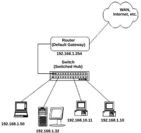
Figure 2-1 Example Configuration 1 - Existing Network with Static IP Address on page 2-3 shows a typical network configuration that uses Static IP
Addressing.
Each of the client devices have a manually assigned IP address in the 192.168.1.0/24 network (i.e., 192.168.1.1 to 192.168.1.254 with a subnet mask of 255.255.255.0). They also have a default gateway address configured (192.168.1.254) this allows the device to route packets to destinations that exist outside of their own LAN.
Router (Default Gateway) WAN, Internet, etc. 192.168.1.254 192.168.1.50 192.168.1.32 192.168.10.11 192.168.1.10 Switch (Switched Hub)
Assume that an Electra Elite IPK II is added to the existing data network. The Network Administrator (or IT Manager) should provide the following:
IP Address (for the CPUII( )-U( ) ETU) Subnet Mask
Default Gateway A spare switch/hub port
First, program the Electra Elite IPK II: PRG10-12-01: 192.168.1.200 PRG10-12-02: 255.255.255.0 PRG10-12-03: 192.168.1.254
A system reset is required for the IP Address changes to take effect.
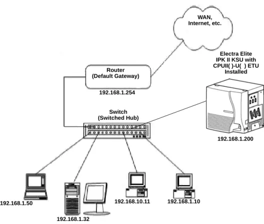
Now connect the CPUII( )-U( ) ETU Ethernet Port to the switch/hub port, using a standard Cat-5 patch cable. The Electra Elite IPK II is now configured on the network and should be accessible by other devices on the network. Refer to Figure 2-2 Example Configuration 1 - Adding the IPK II KSU to the Network.
3.2
Example Configuration 2 - New Network with Dynamic Addressing
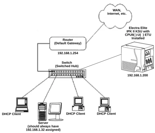
Figure 2-3 Example Configuration 2 - New Network with Dynamic Addressing on page 2-6 shows a typical network configuration using Dynamic IP
Addressing, and the Electra Elite IPK II Internal DHCP server. In most cases, the customer would use an external DHCP server (for example on a Windows 2003 Server) or static addressing (as illustrated in Figure 2-2 Example
Configuration 1 - Adding the IPK II KSU to the Network on page 2-5). However, if the Electra Elite IPK II is to be installed on a new network the Network Administrator may want to use the Electra Elite IPK II internal server (this is called inDHCP).
In this example, the client PCs will obtain an IP address, subnet mask, and default gateway from the inDHCP server. The server will also use DHCP, but
Figure 2-2 Example Configuration 1 - Adding the IPK II KSU to the Network Router (Default Gateway) WAN, Internet, etc. 192.168.1.254 192.168.1.50 192.168.1.32 192.168.10.11 192.168.1.10 Electra Elite IPK II KSU with CPUII( )-U( ) ETU
Installed
192.168.1.200 Switch
The Network Administrator (or IT Manager) should provide the following: IP Address (for the CPUII( )-U( ) ETU)
Subnet Mask Default Gateway
Range(s) of IP Addresses to assign
List of permanent IP addresses, with corresponding MAC Addresses A spare switch/hub port
Figure 2-3 Example Configuration 2 - New Network with Dynamic Addressing Router (Default Gateway) WAN, Internet, etc. 192.168.1.254 DHCP Client Server (should always have 192.168.1.32 assigned)
Electra Elite IPK II KSU with CPUII( )-U( ) ETU
Installed
192.168.1.200
DHCP Client DHCP Client Switch
First, program the Electra Elite IPK II:
A system reset is required for the IP Address changes to take effect.
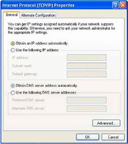
Now connect the Electra Elite IPK II Ethernet Port to the switch/hub port, using a standard Cat-5 patch cable. The Electra Elite IPK II is now configured on the network and its DHCP server is ready to allocate IP addresses. The client PCs should be set to “Obtain IP Address Automatically”. Refer to Figure 2-4 TCP/ IP Properties Screen on page 2-8.
PRG10-12-01: 192.168.1.200 PRG10-12-02: 255.255.255.0 PRG10-12-03: 192.168.1.254 PRG10-13-01: 1: On Switches on inDHCP PRG10-14-01: Min: 192.168.1.50 Max: 192.168.1.150
Defines the range of IP addresses to “lease” PRG10-15-01: MAC: 00-00-86-63-25-87
IP Address: 192.168.1.32
Reserves address 192.168.1.32 for the PC with specified MACa
a. MAC (Media Access Control) addresses are physically assigned to network devices (e.g., NICs). They consist of 12 hexadecimal digits, the first six being the manufacturer and the remaining six are unique to the host. No two MAC addresses are the same.
If the client PCs are now connected to the network (and restarted), they should be assigned and IP address in the range 192.168.1.50 to
192.168.1.150, a subnet mask of 255.255.255.0 and a default gateway of 192.168.1.254. When the server tries to obtain an IP address, the inDHCP server allocates IP address 192.168.1.32, as it is statically assigned to the server’s MAC address.
S
ECTION4
T
ESTING
THE
E
LECTRA
E
LITE
IPK II N
ETWORK
C
ONNECTION
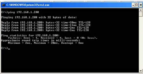
To test the Electra Elite IPK II network connection, it is possible to use the ICMP (Internet Control Message Protocol) “Ping” command. This basically sends a small amount of data from one device to another and then waits for a reply. This test confirms that the IP addressing and physical connection are good. To perform this test, from a Windows PC:1. Click Start. 2. Click Run... .
3. In the Open dialogue box, type command. 4. Click OK.
A Command prompt window opens.
5. Type ping 192.168.1.200.
Figure 2-5 Testing the Network Connection shows that the Electra IPK II system has replied to the Ping request - this indicates that the Electra Elite IPK II system is correctly connected to the network.
IP Extensions
3
IP Extensions
S
ECTION1
I
NTRODUCTION
1
The Electra Elite IPK II system supports the use of IP Phones. These telephones have the same look and functionality as typical multiline telephones, but are connected to the CPUII( )-U( ) ETU via IP rather than being hardwired to an ESI port.
There are two types of telephones that can be used:
IP Multiline Telephone
This is looks like a standard system telephone, but has RJ-45 ports on the back for connection to the LAN, rather than RJ-11. The following IP telephones are available:
ITH-4D-3 TEL ITH-8D-2/3 TEL ITH-16D-2/3 TEL
Electra Elite IPK Multiline Telephone with an IP-R Unit
This is a standard display Electra Elite IPK multiline telephone with an IP-R Unit attached to its base. This option allows IP to be added to the following types of existing Electra Elite IPK multiline
telephones:
DTH-8D-1 TEL DTH-16D-1 TEL
The programming and operation of both types of telephones are identical - only the hardware is different. This document refers to IP Phones - this relates to both types of Electra Elite IPK telephones.
S
ECTION2
IP
TO
TDM C
ONVERSION
When an IP telephone calls an Electra Elite IPK multiline telephone, single line telephone or trunk, the speech has to be converted from IP to TDM (Time Division Multiplexing) technology. The VoIP ETU provides this function. Each VoIP ETU has a number of DSP resources on the ETU, each one can convert a speech channel from IP to TDM and vice versa.
It is possible for Electra Elite IP Phones to talk directly to other Electra Elite IP Phones without using a VoIP ETU DSP resources. (Refer to Section 7 Peer-to-Peer on page 3-9.)
2.1
IP Telephones (ITH)
The IP telephone operates in the same way as an Electra Elite IPK multiline telephone - it has all of the features and flexibility you would expect from an Electra Elite IPK multiline telephone. The difference is that the IP telephone has an RJ-45 for connection to an IP network, rather than an RJ-11 for connection to an ESI ETU.
2.2
Electra Elite IPK Multiline Telephone (DTH) with IP Adapter
An IP Adapter is an add-on module for an Electra Elite IPK II multiline telephone. The IP Unit or adapter clips on to the bottom of the Electra Elite IPK II multiline telephone, allowing connection to the Electra Elite IPK II system using IP.Do not connect the Electra Elite IPK multiline telephone to an ESI port when the IP Unit is installed.
Refer to the Electra Elite IPK II System Hardware Manual for detailed instructions for installing the IP-R Unit.
S
ECTION3
P
OWER
F
AIL
A
DAPTER
The power fail adapter is an add-on module for the IP telephone (not the IP-R Unit). It allows connection to an analog trunk if the power were to fail, or the IP telephone loses connection to the Electra Elite IPK II system.
No programming is required on the Electra Elite IPK II to support this adapter. Figure 3-2 Electra Elite IPK II Multiline Telephone with IP-R(IPK) Unit
3.1
Connecting to an IP Telephone
The Power Fail Adapter connects to a line. At a small branch office, for example, this may be the same line that is used for faxes/modems/etc. The handset is also connected to the Power Fail Adapter - it is necessary to unplug it from the IP telephone and reconnect to the adapter. This allows the speech path to be redirected to the handset in the event of a power/network failure.
Figure 3-3 Power Fail Adapter Connection IPK II CPU
VOIP MG16
Switch/Hub
IP Telephone IP Telephone (with Power Fail Adapter)
PSTN An alo g Tr un k Public Switched Telephone Network Connect to Analog Line RJ-11 Connector PSTN Button
Press for Analog Mode Release for IP Mode
Volume Control (Adjusts handset volume for
Analog Mode only)
Handset (curly-cord) Connection IP Telephone
3.2
Operation During Power Failure
In the event that the telephone becomes disconnected from the power supply (e.g., power cut) the telephone display is blank.
To make a call, lift the handset to receive dial tone from the analog line. Dial as normal.
If a call is received on the analog line, the Power Fail Adapter rings. Lift the handset to answer.
In the event the telephone is connected to the power supply, but disconnected from the Electra Elite IPK II system (e.g., Data network failure), the IP
telephone attempts to reconnect. If this fails, press the button on the back of the adapter. This puts the IP telephone into analog node. The telephone display shows “LINE -> PSTN”.
To make a call, lift the handset to receive dial tone from the analog line. Dial as normal.
If a call is received on the analog line, the Power Fail Adapter rings. Lift the handset to answer.
Handsfree (Speaker) mode is not supported on calls made to or from the Power Fail Adapter the handset must always be used.
S
ECTION4
LAN C
ONNECTION
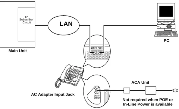
As illustrated in Figure 3-5 Typical Network IP Connection, the IP telephone/IP-R Unit has two RJ-45 connections on the back side - marked “PC” and “LAN”. This allows the IP telephone and a PC to share one cable run and switch/hub port.
If installing an IP telephone at a location that already has a PC connected to the data network, it is possible to use either of the following methods:
Use a different cable and:
leave the PC connected to the LAN
patch a switch/hub port to a new cable run
connect a Cat 5 straight-through cable from the wall outlet to the “LAN” port on the IP telephone.
Share the existing cable and:
unplug the cable from the PCs network card (NIC) connect that cable to the “LAN” port on the IP telephone
connect a new straight-through patch lead from the PC NIC to the “PC” port on the IP telephone.
Figure 3-5 Typical Network IP Connection
LAN
AC Adapter Input Jack
ACA Unit Main Unit
Not required when POE or In-Line Power is available
IP Subscriber
Circuit
S
ECTION5
P
ROVIDING
P
OWER
IP telephones require power to function. This can be provided in various ways:
5.1
Local Power
The IP telephone and IP-R Unit have a connector for external power. This is supplied by a AC adapter that outputs 27V DC. This means that a main socket is required in the vicinity of each IP Phone, and loss of mains power in the building will prevent the phones from working.
You should only use the power supply supplied by NEC.
5.2
Powered Patch Panel
A powered patch panel has two RJ-45 connectors per IP Phone. One port connects to the switch/hub, and the other port connects to the IP Phone. The patch panel has an integral power supply that adds power to the spare pins of the RJ-45.
When the IP Phone is connected to the powered patch panel, it automatically receives its power via the spare pairs on the Cat-5 cable - there is no need for a local power adapter.
5.3
Power Over Ethernet (PoE)
A PoE switch is a switched hub that also provides power over the spare pairs. The switch can be used with any device (not just IP phones) and will detect if power is required or not. As all of the phones receive their power from one device, it is easy to protect the IP phones from loss of power (by connecting the PoE switch to a UPS).
S
ECTION6
DIP S
WITCH
S
ETTINGS
There is a DIP switch on the bottom of the IP telephone (SW2) and the IP-R Unit (SW1). This determines the type of power device to be connected. Please refer to Table 3-1 DIP Switch Settings for the correct switch settings.
Figure 3-6 IP-R Unit Adapter DIP Switch Settings
Table 3-1 DIP Switch Settings
Device DIP Switch Setting
NEC AC Adapter 1 NEC Powered Patch Panel 1 Cisco Powered Patch Panel 2 NEC BlueFire 200/24 1 Cisco PoE Switch 2
S
ECTION7
P
EER
-
TO
-P
EER
An IP telephone can send and receive RTP packets to/from another IP telephone without using DSP resources on a VOIP ETU. This operation only allows Intercom calls between the IP telephones.
If an Electra Elite IPK II multiline telephone, or trunk line is required, a DSP resource is needed and a VOIP ETU must be installed. If, while on a peer-to-peer call, a conference call is initiated, the peer-to-peer connection is released and a new non peer-to-peer connection is created using the VOIP ETU. If the third party drops out of the conversation, the call reverts to a peer-to-peer call (silence may be heard while this conversion is made by the system).
Although the peer-to-peer feature is supported for IP Station-to-IP Station calls, the Elite IPK II KSU must still have a registered VOIP ETU installed in the system.
With Barge-In, a short silence may be heard if the following occurs:
a peer-to-peer call receives a Barge-In without a Barge-In tone. a peer-to-peer call receives a Barge-In with Monitor mode. when the established Barge-In is disconnected.
The Peer-to-Peer feature is a programmable feature that may be enabled or disabled by accessing Data Program 10-26-01 – Peer to Peer.
S
ECTION8
P
ROGRAMMING
The first step to connecting IP telephones to the Electra Elite IPK II system is to connect the IPK II system to the customer’s data network (refer to Chapter 2 General IP Configuration). Next, program the VoIP ETU and associated IP telephone settings. To complete the installation, program the IP telephone.
The programming commands required to complete this installation are located in Chapter 5 Programming. This section provides a brief description of the commonly used commands:
Â
10-12-01 CPUII Network Setup - IP AddressSelect the IP address for the IP connection (default: 172.16.0.10). A static IP address is required by the CPU II.
Â
10-12-03 CPUII Network Setup - Default GatewayIf required, select the default gateway IP address to be used when using a router (default: 0.0.0.0).
Â
10-26-01 Peer-to-PeerUse this Data Program to enable or disable the Peer-to-Peer feature between Megaco IP Stations.
Disabling this feature results in Megaco IP Station-to-Megaco IP Station calls utilizing DSP Resources.
Â
15-05-15 IP Telephone Terminal Basic Data Setup - CODEC TypeFor each IP telephone, set which CODEC Type to use.
Â
84-05-01 VOIP IP Address - IP AddressFor each VOIP ETU, enter the IP address for the VOIP ETU (default: slot 1=172.16.0.20, slot 2 = 172.16.0.21, etc.). This entry becomes invalid if Program 84-04 is set to "1" (DHCP enabled).
Â
84-06-01 VoIP Info - RTP Port NumberFor each VOIP ETU, enter the RTP port number (default: 10020).
Â
84-11-28 Dterm IP CODEC Information Basic Setup - Audio Capability PriorityFor each Type, set the CODEC to use (default: G.711).
8.1
System Tones and Ring Tones
IP Phones do not use Program 80-01: Service Tone Setup entries. The tones are generated locally by the IP telephone. When a Door Box chime rings an IP telephone, the system activates the chimes using a ring command. Because of this, if the volume is adjusted while the door chime is sounding, the ringing volume of the IP Phone will be adjusted.
8.2
Music on Hold
In addition, Music on Hold is also provided by the IP telephone. The settings in Program 10-04 : Music on Hold Setup are ignored except to determine whether or not music should be provided. If 10-04-02 is set to "0", no music on hold will be heard. If 10-04-02 is set to "1" or "2", music will be provided by the IP telephone, but there is only one music selection.
S
ECTION9
C
ONFIGURATION
E
XAMPLES
The following examples below show typical scenarios and basic programming required. These examples assume that the programming steps below are performed on a default system (i.e., no existing configuration).
9.1
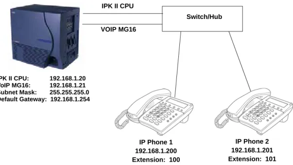
Example Configuration 1 - Static IP Addressing, One LAN
This example shows IP Phone connected to a single LAN (no routers), with static IP Addresses.
Figure 3-7 Example Configuration 1 - Static IP Addressing, One LAN
Programming - CPUII:
10-12-01 : CPUII Network Setup - IP Address 10-12-02 : CPUII Network Setup - Subnet Mask 10-12-03 : CPU II Network Setup - Default Gateway
192.168.1.20 255.255.255.0 192.168.1.254
Programming - VoIP ETU:
84-05-01 : VOIP IP Address - IP Address (Slot #) 192.168.1.21
Programming - IP Phones:
DHCP Mode IP Address Subnet Mask Default Gateway
84-05-03: VOIP Address - Master/Slave Master 84-05-04: VOIP Address - Subnet-Mask
Disabled 192.168.1.200 255.255.255.0 192.168.1.254 (Ext. 100) 255.255.255.0 IPK II CPU VOIP MG16 Switch/Hub IP Phone 1 192.168.1.200 Extension: 100 IP Phone 2 192.168.1.201 Extension: 101 IPK II CPU: 192.168.1.20 VoIP MG16: 192.168.1.21 Subnet Mask: 255.255.255.0 Default Gateway: 192.168.1.254
9.2
Example Configuration 2 - Dynamic IP Addressing, One LAN
This example shows System IP Phones connected to a single LAN (no routers), with dynamic IP Addresses. The DHCP server could be:customer supplied (e.g., Windows 2003 server) inDHCP internal DHCP server.
In this case, additional programming would be required. Refer to Chapter Chapter 2 General IP Configuration and Figure 3-8 Example Configuration 2 - Dynamic IP Addressing, One LAN.
Figure 3-8 Example Configuration 2 - Dynamic IP Addressing, One LAN
Programming - CPUII:
10-12-01 : CPUII Network Setup - IP Address 10-12-02 : CPUII Network Setup - Subnet Mask 10-12-03 : CPUII Network Setup - Default Gateway 10-13-01 : In-DHCP Server Setup - DHCP Server Mode 10-14-01 : Managed Network Setup (Scope 1)
192.168.1.20 255.255.255.0 192.168.1.254 On 192.168.1.200 Min 192.168.1.250 Max
Programming - VoIP ETU:
10-16-01: Option information Setup - Router (Route No. 3) 10-16-05 : Option information MGC (No. 129)
192.168.1.254 192.168.1.21 IPK II CPU VOIP MG16 Switch/Hub IP Phone 1 192.168.1.200 Extension: 200 IP Phone 2 192.168.1.201 Extension: 201 IPK II CPU: 192.168.1.20 VoIP MG16: 192.168.1.21 Subnet Mask: 255.255.255.0 Default Gateway: 192.168.1.254
S
ECTION10
E
XAMPLE
C
ONFIGURATION
3 - S
TATIC
IP A
DDRESSING
, R
OUTED
WAN
This example shows IP Phones connected to an Electra Elite IPK II system over a Wide Area Network (WAN), with static IP addressing. This is a typical scenario - a small branch office connecting to an Electra Elite IPK II at the main office.
Programming - IP Phones
DHCP Mode (Ext. 200):
84-05-03 : VOIP Address - Master/Slave Master 84-05-04 : VOIP Address - Subnet-Mask 84-05-05 : VOIP Address - Default Gateway
Enabled 255.255.255.0 192.168.1.254 IPK II CPU VOIP MG16 Switch/Hub IPK II CPU: 192.168.1.20 VoIP MG16: 192.168.1.21 Subnet Mask: 255.255.255.0 Default Gateway: 192.168.1.254 Router 192.168.1.254 Switch/Hub WAN
(Leased Line, Frame Relay, etc.)
Router 192.168.2.254
S
ECTION11
IP P
HONE
P
ROGRAMMING
I
NTERFACE
This section describes how to access the programming interface for IP Phones. The following describes how to access the User Menu.
1. Using an IP Phone, enter program mode by pressing Hold Transfer #.
The IP User Menu is displayed.
2. On the IP User Menu select the options for programming the individual IP Phone. Settings are listed in Table 3-2 IP Phone Programming User Menu Options.
Programming - CPUII:
10-12-01 : CPUII Network Setup - IP Address 10-12-02 : CPUII Network Setup - Subnet Mask 10-12-03 : CPUII Network Setup - Default Gateway
192.168.1.20 255.255.255.0 198.168.1.254
Programming - VoIP ETU:
84-05-01 : VOIP IP Address - IP Address (Slot #) 192.168.1.21
Programming - IP Phones
DHCP Mode: IP Address: Subnet Mask: Default Gateway:
84-05-03 : VOIP Address - Master/Slave Master 84-05-04 : VOIP Address - Subnet-Mask 84-05-05 : VOIP Address - Default Gateway
Disabled 192.168.2.200 255.255.255.0 198.168.2.254 255.255.255.0 192.168.1.254
Table 3-2 IP Phone Programming User Menu Options
Programming Option Default
1. Network Settings - DHCP Mode Disable
Enable
Enabled 2. MGC IP Address 0.0.0.0 3. Extension Numbering 0
4. Volume Setting Select the volume levels for ringer, handset, headset speaker, LCD contrast. 5. Ring Settings Custom Ring Disable
(Customizes IP Phones ring pattern)
3. Press the SAVE softkey to save the entries and return the IP Phone to an idle condition.
7. PC Port Setting PC Port VLAN Mode Disable
8. System Information (for viewing only)
DHCP Mode TFTP IP Address VLAN Mode VLAN ID VLAN Priority MGC IP Address DRS Mode CDP Mode Speed & Duplex Ring Pattern MAC Address Firmware Version Enable 0.0.0.0 Disable 7 5 0.0.0.0 Disable Enable Autoneg High 00 60 b9 c1 23 5d (Megaco) 01.27 9. Advance Settings 1. Download Settings 2. Download 3. DRS Settings 4. CDP Mode 5. Type of Service 6. Soft Reset 7. Default Value 8. Diagnostic Utility 9. Port Settings
Table 3-2 IP Phone Programming User Menu Options (Continued)
S
ECTION12
DHCP S
ERVER
C
ONFIGURATION
It is possible to use either an external DHCP server (e.g., Windows 2003 Server) or the Electra Elite IPK II internal DHCP server. If you intend to use either of these methods with IP Phones, the DHCP server needs to be configured to supply the MGC, DRS, Gateway, TFTP address.
If you are using the internal DHCP server, simply enable the DHCP server (refer to 9.2 Example Configuration 2 - Dynamic IP Addressing, One LAN on page 3-12), then specify the MGC address in PRG10-16-05.
Â
10-16-05 Option Information Setup MGCSpecify the MGC address to provide to the System IP Phones. This is usually the VoIP ETU address.
If using an external DHCP server, it is necessary to add a new Option Code to the DHCP scope for the MGC address. The method for adding this service varies depending on the DHCP server used.
12.1
DHCP Server Configuration Example
The example below shows the necessary steps to add Option 129 to a Windows 2000 Server.
1. Enter Computer Management and expand Service and Applications. 2. Right click on DHCP and click on Set Predefined Options (refer to
Figure 3-10 DHCP Server Configuration on page 3-17).
3. When the Predefined Options and Values dialogue box opens, click on Add.
4. Enter the information In the Option Type dialog box and click OK.
A new Option type for the DHCP server is created.
5. To add the Option Type to the DHCP scope and specify the value to use, locate the scope that is currently being used (there may be more than one) within Computer Management.
6. Right click on Scope Options then click on Configure Options. 7. Scroll down to Option 129 (created in steps 1 to 5) and check the box.
8. You will then be prompted to enter a value.
9. Enter the MGC address - this is usually the VoIP ETU IP address (PRG 84-05-01) and click OK.
10. The DHCP server is now ready to provide IP Phones with the MGC address.
S
ECTION13
C
ONFIGURING
Q
UALITY
OF
S
ERVICE
NEC recommends configuring Quality of Service (QoS) to ensure that the speech quality is not affected by other data on the network. QoS is discussed further in Chapter 6 Network Design Considerations.
The Electra Elite IPK II system supports:
IEEE802.1q (VLAN Tagging) IEEE802.1p (Priority)
With the VLAN tagging mode, the Electra Elite IPK II system can handle packets with or without a VLAN tag. If the VLAN ID of a packet is different from the registered one, that packet will be dropped.
13.1
Layer 2 Priority Control
Layer 2 priority control can be enabled on an ethernet switch, if it supports VLAN tagging. This allows layer 2 prioritization.
Using a switch that supports 802.1p allows: priority control
reduction of unnecessary packets (e.g., broadcast packets) and provides circuitry by restricting a broadcast domain
13.1.1 Programming Layer 2 Priority Control
To program Layer 2 for System, VLAN/QoS, use the following programs.
Â
84-09-01 VLAN Setup - VLANEnable the VLAN mode for the system (0=Disable, 1=Enable). The system must be reset in order for the change to take effect. If the VLAN mode is enabled, the Electra Elite IPK II system sends all packets with a VLAN tag - if disabled, no VLAN tag is sent in the packets.
Â
84-09-02 VLAN Setup - VLAN IDEnter the ID to be used for the VLAN (1~4094). The system must be reset in order for the change to take effect.
Â
84-09-03 VLAN Setup - PriorityEnter the priority of the VLAN (0~7). The system must be reset in order for the change to take effect.
To program Layer 2 Priority Control for IP Phones VLAN/QoS:
1. Use the IP Phone to enter the telephone program mode by pressing Hold Conf #.
This enters the IP program mode to select the settings for the individual phone. The flashing item is the current selection.
2. Press the SAVE softkey to save the entries and return the telephone to an idle condition.
13.2
Layer 3 (ToS) Priority Control
The router-supported ToS controls routing priority of packets by following the ToS field. It is possible to give priority to the voice packet using the ToS field.
There are two types of ToS formats: DiffServ and IP Precedence. Before programming the router, make sure to check which type is supported by the router.
The Electra Elite IPK II system can set the ToS value for each protocol, and Voice Control. This setting allows flexible prioritization.
13.2.1 Programming Layer 3 Priority Control
To program Layer 3 VLAN/QoS use the following programs.
Â
84-10-01 ToS Setup - ToS ModeFor the Protocol type (1=CPU, 2=MGC, 3=Megaco, 4=Reserved, 5=RTP/RTCP, 6=SIP, 7=CCISoIP), select the ToS mode (0=Disable, 1=IP Precedence, 2=Diffserv).
Â
84-10-02 ToS Setup - Priority, IP PrecedenceFor the Protocol type (1=CPU, 2=MGC, 3=Megaco, 4=Reserved, 5=RTP/RTCP, 6=SIP, 7=CCISoIP), if Program 84-10-01 is set to "1", select the precedence (0=Low, 7=High).
Â
84-10-03 ToS Setup - Low DelayFor the Protocol type (1=CPU, 2=MGC, 3=Megaco, 4=Reserved, 5=RTP/RTCP, 6=SIP, 7=CCISoIP), if Program 84-10-01 is set to "1", select the delay (0=Normal Delay, 1=Low Delay).
Â
84-10-04 ToS Setup - Wide Band (Throughout)For the Protocol type (1=CPU, 2=MGC, 3=Megaco, 4=Reserved, 5=RTP/RTCP, 6=SIP, 7=CCISoIP), if Program 84-10-01 is set to "1", select the throughput (0=Normal Throughput, 1=High Throughput).
Â
84-10-05 ToS Setup - High ReliabilityFor the Protocol type (1=CPU, 2=MGC, 3=Megaco, 4=Reserved, 5=RTP/RTCP, 6=SIP, 7=CCISoIP), if Program 84-10-01 is set to "1", select the reliability (0=Normal Reliability, 1=High Reliability).
Â
84-10-06 ToS Setup - Low CostFor the Protocol type (1=CPU, 2=MGC, 3=Megaco, 4=Reserved, 5=RTP/RTCP, 6=SIP, 7=CCISoIP), if Program 84-10-01 is set to "1", select the low cost mode (0=Normal Cost, 1=Low Cost).
Â
84-10-07 ToS Setup - Priority (D.S.C.P. - Differentiated Services Code Point)For the Protocol type (1=CPU, 2=MGC, 3=Megaco, 4=Reserved, 5=RTP/RTCP, 6=SIP, 7=CCISoIP), if Program 84-10-01 is set to "2", select the Diffserv priority (0~63).
S
ECTION14
IP T
ELEPHONE
R
EGISTRATION
AND
D
ELETION
When a IP Phone connects to the Electra Elite IPK II system, it is assigned the first available port, starting from the value set in Program 11-02-01.
The ports are allocated in blocks of four.
For example:
Insert an MG16 ETU.
Program 11-02-01 Extension Numbering.
Configure a System IP Phone and connect to the LAN. The IP Phone takes port 17 (extension 216 by default).
Ports 18~ 20 are also allocated for use by IP Phones - the next IP Phone to connect takes port 18.
If a second extension ETU (e.g., ESI ETU or SLI ETU) is inserted, it takes port 21 and higher.
When connecting an IP Phone, the MAC address (ID) is automatically registered in Program 15-05-02. If the registration in Program 15-05-02 is made manually (before connecting the telephone) it uses the assigned port number when the telephone is connected. The MAC address is printed on the barcode label on the bottom of the telephone or IP-R Unit. It is a 12-digit alphanumeric number, ranging from 0~9 and A~F.
To delete a telephone registration:
Enter Program 90-23-01, then enter the extension number of the IP Phone. Press 1 and then Hold to delete the registration.
S
ECTION15
S
YSTEM
IP P
HONES
AND
A
NALOG
T
RUNKS
NEC does not recommend using IP Phones with analog trunks. Due to the nature of analog-to-digital conversion, considerable echo is created, which cannot be removed by the Electra Elite IPK II echo canceller. Digital (ISDN) trunks do not suffer from this problem.
For outgoing calls:
Ensure that there are no analog trunk ports (COI ETU or TLI ETU) in the trunk routes (PRG 21-02).
For incoming calls:
Ensure that there are no IP Phones in the trunk targets (PRG22-04 and 22-07).
For transferred calls:
It is not possible to stop an analog trunk call being transferred to an IP Phone. It is important that the end-user is made aware of this limitation.
S
ECTION16
F
IRMWARE
U
PGRADE
P
ROCEDURE
Occasionally, NEC releases a new version of firmware for the IP Phones. This firmware can be applied automatically or manually.
16.1
Manually Upgrading Firmware
Manually upgrading the firmware uses a uses a TFTP server, but requires the engineer visit each IP Phone individually. This may take longer, but is more controlled as the downloads can be staggered to avoid excessive bandwidth utilization.
To manually upgrade the firmware: 1. Install and configure a TFTP server.
2. Copy the firmware file (apph248.hex for IP Adapter or apph248.out for IP Phone) to the default TFTP directory.
3. On the IP Phone, enter programming mode (Hold, Conf, , #). 4. Enter Maintenance Mode (Hold, #, 0).
5. Enter the TFTP server IP address in “Option 1 - Download settings”. 6. Enter Download menu (option 2).
7. Press 1 - for “Program”. 8. Press the softkey.
The IP Phone attempts to download the firmware from the TFTP server and reboots when the download is complete.
16.2
Checking the Firmware Version
To check the IP Phone firmware version:1. On the System IP Phone, enter programming mode (Hold, Conf, , #). 2. Enter 8 - for Information.
3. Press the Up softkey.
The Firmware Version is displayed.
16.3
Upgrading Automatically
This procedure causes all IP Phones to attempt firmware upgrade the next time they connect to the CPU II. This can make the upgrade procedure easier, as it is not necessary to visit every telephone to perform the upgrade.
This can cause problems if, for example, a PoE (Power over Internet) switch is used. In this case, when the PoE switch is powered up, all telephones connect to the TFTP server at the same time. This causes a large amount of data for
To avoid this, connect the telephones to the PoE switch gradually, allowing time for each telephone to upgrade before connecting the next.
To enable automatic upgrade:
1. Install and configure an TFTP server.
2. Copy the firmware file (apph248.hex for IP-Adapter or apph248.out for IP-Phone) to the default TFTP directory
3. Set the server mode to TFTP in PRG84-07-01 and specify the IP address of the TFTP server (this is the PC where the TFTP software is installed) in PRG 84-07-02.
4. For each type of System IP Phone, set the Hardware type: PRG 90-22-01.
5. The telephones that are currently supported are: 02: IP Adapter
04: IP Phone (North America)
6. Set the required firmware version in PRG 90-22-02. This should be set to the version number that is available on the TFTP server.
7. Reboot the IP Phone. The IP Phone compares the version of firmware currently installed with the firmware specified in PRG90-22. If they are different, the IP Phone attempts to download the firmware from TFTP. If the download is successful, the IP Phone checks that the firmware it has installed matches PRG 90-22. If this is the case, the telephone
IP Netw
or
king
4
IP Networking
S
ECTION1
I
NTRODUCTION
1
IP Networking uses VoIP technology to connect two or more telephone systems together. This allows calls to be made between sites without using the public telephone network. This can save a considerable amount of money, and can makes communication between sites much easier.
There are two types of IP Networking available on the Electra Elite IPK II – IPK II CCIS Network and SIP trunks. These methods are explained below.
S
ECTION2
IPK II CCIS
O
IP N
ETWORK
The IPK II CCIS Network package provides a seamless connection of multiple systems into a single “virtual” communications system using or VoIP lines with a unified numbering plan.
IPK II CCIS Network allows many offices to connect their Electra Elite IPK II systems so they appear as one. This will give them the ability to have only one operator to manage the system and share one voice mail system within the network.
An extension user in the network can easily dial another extension or transfer a call within the IPK II CCIS Network system. Calls are passed from network node to network node using a protocol that contains
information about the source of the call, the type of call and the destination of the call.
IPK II K-CCIS is explained in detail in the Electra Elite IPK II Key-Common Channel Interoffice Signaling (K-CCIS) Manual. Please refer to this for a complete description and installation instructions.
S
ECTION3
IP T
RUNKS
The SIP Trunks method of networking allows connection to SIP devices. This could be a PBX system or a third-party product. The feature set is limited when using SIP, it is not possible to use the advanced networking features (if these features are
required, use IP CCIS.
Refer to Chapter 8 SIP Trunking for a a detailed description of SIP trunking and for set up instructions.
To set up IP trunks:
4. Connect the system to the Data Network. (Refer to Chapter 2 General IP Configuration for detailed instructions.)
5. Configure the IP trunks.
6. Configure the CCISoIP or SIP information. 7. Configure the F-route.
3.1
Configure IP Trunks
When installing a PVA(X)-U10 ETU in the Electra Elite IPK II system, external line ports are allotted in accordance with the number of Licensed ports for the particular IP Application.
The Electra Elite IPK II system now has the required information about the remote destinations and the SIP/CCISoIP configuration is complete. The only remaining task is to configure F-Route to route calls to remote destinations via the IP trunks. F-Route configuration is discussed in detail in the Automatic Route Selection (ARS) feature in the Electra Elite IPK II Programming Manual. A basic list of the programming commands required for F-route is shown in the example below.
S
ECTION4
E
XAMPLE
C
ONFIGURATIONS
4.1
Network Configurations
Figure 4-1 Example IP Network Configuration shows four sites networked via IP trunks. Each site has a Point Code and an IP address.
The programing for Office A and C is shown below. This would be sufficient programming to make a call from Office A to Office C.
IP Address (PVA): 192.168.1.10 Point Code: 00001
Ext. 1000 Ext. 1100
Electra Elite IPK II
Office A IP Network (Intranet) Ext. 1200 IP Address (1st PVA): 192.168.1.20 IP Address (2nd PVA): 192.168.1.21 Point Code: 00002
Electra Elite IPK II
Office B Ext. 1300 IP Address: 192.168.1.30 Point Code: 00003 PBX Office C Office D IP Address: 192.168.1.40 Point Code: 00004 PBX
4.2
Electra Elite IPK II CCIS over IP Programming Example 1
This is an example of Electra Elite IPK II program data assignments for a 4-digit Closed Numbering Plan using Closed Number Blocks. The following system configurations are used for all four systems:
Each system is a single cabinet expanded port package with one B64-U20 KSU.
Each system has 16 Multiline Terminals. Each system has eight analog Trunks.
It is assumed that the systems were defaulted (first power on) with the following cards installed as described in the following table.
Figure 4-2 Programming Example 1 Electra Elite IPK II System A (1000) Electra Elite IPK II System B (1100) NEAX System D (1300) NEAX System C (1200) Point Code: 00002 Address: 1st IAD: 192.168.1.20 2nd IAD: 192.168.1.21 IP Network (Intranet) Point Code: 00004 Address: 192.168.1.40 Point Code: 00003 Address: 192.168.1.30 Point Code: 00001 Address: IAD: 192.168.1.10
Systems C and D are NEAX systems. Refer to the applicable system manuals for programming details.
Card Interface Slot Assignment (PGR 10-03 ETU Setup )
4.2.1 Digital Trunk Assignments
Use the table below to make the appropriate assignments for digital trunks. Slot Card Type During 1st Power On
Card Type and Ports
System A System B
Card Type Ports Card Type Ports
1 ESI(8)-U10 ESI(8)-U10 Station 1 ~ 8 ESI(8)-U10 Station 1 ~ 8
2 ESI(8)-U10 ESI(8)-U10 Station 9 ~ 16 ESI(8)-U10 Station 9 ~ 16
3 None None Not Applicable None Not Applicable
4 COI(8)-U10 COI(8)-U10 Trunks 1 ~ 8 COI(8)-U10 Trunks 1 ~ 8
5 None None Not Applicable None Not Applicable
6 None None Not Applicable None Not Applicable
7 IAD(8)-U10 CCISoIP Trunks 9 ~ 16 CCISoIP Trunks 9 ~ 16
8 None None Not Applicable CCISoIP Trunks 17 ~ 24
0A None None Not Applicable None Not Applicable
System A System B
PRG 10-03-01 ETU Setup - Logical Port Number
Insert IAD in Cabinet 1, Slot 7. Verify PRG 10-03-01 (ETU Setup).
PRG 10-03-01 ETU Setup - Logical Port Number
Insert IAD in Cabinet 1, Slot 7. Insert IAD in Cabinet 1, Slot 8. Verify PRG 10-03-01 (ETU Setup). PRG 14-05-01 Trunk Group
Assign Trunks 9~16 in Trunk Group 15.
PRG 14-05-01 Trunk Group
Assign Trunks 9~16, 17~24 in Trunk Group 15.
PRG 22-02-01 Incoming Call Trunk Setup
Set Trunks 9-16 as Tie Line (LK 6).
PRG 22-02-01 Incoming Call Trunk Setup
Set Trunks 9-16, 17~24 as Tie Line (LK 6).
4.2.2 VoIP Address Assignments
Use the table below to make the appropriate assignments for VoIP addresses.
4.2.3 CCIS Availability
Use the table below to make the appropriate assignments for CCIS availability.
System A System B
PRG 84-05-01 VoIP Address Setup - IP Address
Slot 7, Assign IP Address 192.168.1.10.
PRG 84-05-01 VoIP Address Setup - IP Address
Slot 7, Assign IP Address 192.168.1.20.
Slot 8, Assign IP Address 192.168.1.21.
PRG 84-05-02 VoIP Address Setup - LAN Interface
Slot 7, Assign Auto.
PRG 84-05-02 VoIP Address Setup - LAN Interface
Slot 7 & 8, Assign Auto. PRG 84-05-04 VoIP Address Setup -
Subnet Mask
Slot 7, Assign 255.255.255.0.
PRG 84-05-04 VoIP Address Setup - Subnet Mask
Slots 7 & 8, Assign 255.255.255.0. PRG 84-05-05 VoIP Address Setup -
Default Gateway Slot 7, Assign 0.0.0.0.
PRG 84-05-05 VoIP Address Setup - Default Gateway
Slots 7 & 8, Assign 0.0.0.0.
System A System B
PRG 50-01-01 CCIS System Setup - CCIS Availability
Select option 1 (Enable). Enables the CCIS Feature.
PRG 50-01-01 CCIS System Setup - CCIS Availability
Select option 1 (Enable). Enables the CCIS Feature. PRG 50-02-03 Connecting System
Settings - Originating Point Code (DIT Only)
Route ID 9 = 01
Route ID 9 is designated for the Host Originating Point Code (OPC.)
PRG 50-02-03 Connecting System Settings - Originating Point Code (DIT Only)
Route ID 9 = 02
Route ID 9 is designated for the Host Originating Point Code (OPC.).
4.2.4 IP CCISoIP Assignment
Use the table below to make the appropriate assignments for CCIS over IP.
4.2.5 CCIS Assignment
Use the table below to make the appropriate system-wide CCIS assignments.
System A System B
PRG 50-03-01 CCIS Destination System Settings - Destination Point Code
System ID 1~255 – Enter Destination Point Code.
System ID 1 = DPC 02
PRG 50-03-01 CCIS Destination System Settings - Destination Point Code
System ID 1~255 – Enter Destination Point Code.
System ID 1 = DPC 01 PRG 50-03-03 CCIS Destination
System Settings - IP Address System ID 1~255 – Enter Destination System IP Address.
System ID 1 = 192.168.1.20
PRG 50-03-03 CCIS Destination System Settings - IP Address System ID 1~255 – Enter Destination System IP Address.
System ID 1 = 192.168.1.10
System A System B
PRG 50-03-01 CCIS Destination System Settings - Destination Point Code System ID 1~255
Enter Destination Point Code. Default not assigned.
PRG 50-03-01 CCIS Destination System Settings - Destination Point Code
System ID 1~255
Enter Destination Point Code. Default not assigned. PRG 50-04-01 CCIS Office Code
Assignment
Assign up to four digits. Default not assigned.
PRG 50-04-01 CCIS Office Code Assignment
Assign up to four digits. Default not assigned. PRG 50-13-01 CCIS Centralized
Response Timeout Assignment - IAI Response Timer
Enter 00~99.
PRG 50-13-01 CCIS Centralized Response Timeout Assignment - IAI Response Timer
Enter 00~99. PRG 50-06-01 CCIS Feature Availability
- Link Reconnect 0 = Not Available 1 = Available (default)
PRG 50-06-01 CCIS Feature Availability - Link Reconnect 0 = Not Available
1 = Available (default)