Content-Aware Radio Resource Management for
IMT-Advanced Systems
Muhammad Syahrir Johal
A thesis submitted to
Lancaster University for the degree of Doctor of Philosophy
1
Abstract
Content-Aware Radio Resource Management for IMT-Advanced Systems
Muhammad Syahrir Johal
Submitted for the degree of Doctor of Philosophy
April 2017
Radio Resource Management (RRM) is crucial to efficiently and correctly manage the
delivery of quality-of-service (QoS) in IMT-Advanced systems. Various methods on radio
resource management for LTE/LTE-Advanced traffic have been studied by researchers
especially regarding QoS handling of video packet transmissions. Usually, cross-layer
optimisation (CLO) involving the PHY and MAC layers, has been used to provide proper
resource allocation and distribution to the entire system. Further initiatives to include the APP
layer as part of CLO techniques have gained considerable attention by researchers. However,
some of these methods did not adequately consider the level of compatibility with legacy
systems and standards. Furthermore, the methods did not wholly address User Equipment (UE)
mobility or performance metrics for a specific data type or a specified period.
Consequently, in this thesis, a content-aware radio RRM model employing a cross-layer
optimiser focusing on a video conferencing/streaming application for a single cell long-term
evolution (LTE) system has been proposed. Based on two constructed look-up tables, the
cross-layer optimiser was found to dynamically adjust the transmitted video data rates depending on
2
performance study of the LTE classical (baseline) simulation model for various distances at a
certain UE velocity. Two performance parameters, namely the average throughput and
measured SINR were matched together to find the most suitable data rates for video delivery in
both the uplink and downlink transmissions.
The developed content-aware RRM model was then tested against the LTE baseline
simulation model, to benchmark its capability to be used as an alternative to existing RRM
methods in the present LTE system. Based on the detailed simulations, the output performance
demonstrated that for video packet delivery in both uplink and downlink transmissions, the
content-aware RRM model vastly outperformed the legacy LTE baseline simulation model with
regard to the packet loss ratio and average end-to-end delay for the same amount of throughput.
The baseline simulation model and the newly developed cross-layer approach were
investigated and compared with practical measurement results in which PodNode technology,
besides other components and supporting simulation software, were used to emulate the LTE
communication system. The first emulation experiment involving the baseline model was
generally in sync with the uplink throughput simulation performance. The second test which
implemented the cross-layer approach employing the look-up table derived from the previous
emulated results, confirmed the viability of the proposed content-aware RRM model to be used
in current LTE or LTE-Advanced systems for improving the performance in the packet loss
ratio and average packet delay.
3
Declaration
I declare that the material presented in this thesis consists of original work undertaken
solely by myself. Whenever work carried out by other authors is referred to in this thesis, it has
been duly referenced. The material presented here has not been submitted elsewhere in entirely
the same form for the award of a higher degree.
4
List of Publications / Contributions
Papers Published:
1. Mohd Khairy Ismail, Muhammad Syahrir Johal and Azmi Awang Md Isa, “Current Developments in LTE-ADVANCED: Radio Resource Management Review”, in proceedings of IEEE Student Conference on Research and Development (SCOReD 2014), 16-17 Dec. 2014.
2. M. K. Ismail, A. A. M. Isa and M. S. Johal, “Review of Radio Resource Management for IMT-Advanced System”, Jurnal Teknologi, Vol. 72, No. 4, 2015, pp. 113-119.
3. MK Ismail, A Awang Md Isa, MS Johal and MSI M Zain, “Current Development in LTE/LTE-Advanced: Adaptive-Proportional Fair Scheduling in LTE”, Journal of Telecommunication, Electronic and Computer Engineering (JTEC), Vol. 7, Issue 1, 2015, pp. 103-108.
4. Juwita Mohd Sultan and Muhammad Syahrir Johal, “Cross Layer Scheduling in WiMAX QoS for Disaster Management”, Journal of Telecommunication, Electronic and Computer Engineering (JTEC), Vol. 7, Issue 2, 2015, pp. 145-151.
5. Mohd Khairy Ismail, Azmi Awang Md Isa, Muhammad Syahrir Johal and Mohd Riduan Ahmad, “Design and Development of Modified Proportional Fair Scheduler for LTE/LTE-Advanced”, ARPN Journal of Engineering and Applied Sciences, Vol. 11, No. 5, March 2016, pp. 3280-3285.
5
Acknowledgements
I would like to thank and express my sincerest gratitude, firstly, to my main supervisor
Professor Garik Markarian who encouraged me to pursue this topic. I honestly and firmly
believe that without his wisdom and insightful suggestions during my work, I would not have
achieved my immediate goal of submitting this thesis for my PhD. This thesis has significantly
benefitted from his invaluable guidance, support and constant encouragement.
I would also like to acknowledge my heartfelt thanks to my supervisors, Associate
Professor Dr Azmi Awang Md Isa and Dr Yosza Dasril for their meaningful and insightful
feedback and advice during the period of my PhD study in UTeM, Malaysia. I much appreciate
their concerns for my intellectual and personal growth.
I am very grateful to my lab colleagues of Room B28 especially Abd Shukur, Juwita, Dr
Dmitry Zvikhachevskiy and Dr Ivan Manuylov. I appreciate our fruitful technical discussions
together and thank them both for being wonderful neighbours during my stay for one and a half
years in Lancaster. Special thanks to Rinicom’s technical staff for their invaluable help and
support in the realisation of my practical testbed investigation, namely Dr Hassan Girach and
Dr Sean Sonander.
I would also like to thank my sponsor who is also my employer, the Universiti Teknikal
Malaysia Melaka, who allowed me to further my PhD study and provided financial support,
without which this research would not have been made possible.
Finally, I would like to thank my parents for their unconditional love and ongoing
support throughout my PhD study. Finally, I would like to thank my beloved wife, Suhaila
6
side, giving their love, support and encouragement through the difficult and arduous times, to
7
Table of Contents
Abstract ... 1
Declaration ... 3
List of Publications / Contributions ... 4
Acknowledgements ... 5
List of Figures ... 10
List of Tables ... 12
List of Abbreviations ... 13
1 INTRODUCTION ... 19
1.1 Research Motivations ... 20
1.2 Research Background ... 21
1.3 Research Objectives ... 23
1.4 Research Methodology ... 23
1.5 Research Contributions ... 24
1.6 Thesis Outline ... 24
2 RADIO RESOURCE MANAGEMENT IN LTE/LTE-ADVANCED SYSTEM... 27
2.1 Introduction ... 27
2.2 LTE Architecture ... 28
2.3 LTE-Advanced Architecture and Protocol Stack ... 34
2.4 eNodeB Protocol Stack and RRM Functions... 37
2.4.1 Semi-Dynamic RRM Features (QoS Parameters, Admission Control and Semi-Persistent Scheduling) ... 41
2.4.2 Fast Dynamic RRM Algorithms ... 43
2.5 Research on RRM for LTE ... 44
2.6 Cross-Layer Design for LTE ... 47
2.7 Summary ... 50
3 THE CLASSICAL (BASELINE) LTE SIMULATION MODEL ... 52
3.1 Simulation Environment ... 53
3.2 Classification of Simulation Tools ... 53
3.2.1 OMNeT++ ... 54
3.2.2 OPNET Modeler (Currently known as Riverbed Modeler [77]) ... 56
3.2.3 NS-2 ... 58
8
3.2.5 MATLAB ... 61
3.3 Single Cell eNodeB Simulation Topology and Parameter setup for Uplink Transmission ... 65
3.4 Analysis of the LTE Uplink Baseline Model Performance ... 70
3.5 Correlation between Output Performance Parameters and SINR ... 73
3.6 Downlink Scenario of the Baseline Model ... 74
3.7 Analysis of the LTE Downlink Baseline Model Performance ... 76
3.8 Correlation between the Output Performance Parameters and SINR for the Downlink Transmission ... 78
3.9 Summary ... 79
4 CONTENT-AWARE RADIO RESOURCE MANAGEMENT MODEL ... 81
4.1 Proposed Look-up Table for the Uplink Content-Aware RRM Model ... 82
4.2 Comparison Parameters ... 84
4.3 Results Analysis of the Uplink Transmission ... 85
4.3.1 Scenario 1 ... 86
4.3.2 Scenario 2 ... 89
4.3.3 Scenario 3 ... 91
4.3.4 Mobility Analysis for the LTE Uplink Video Packet Transmission ... 93
4.4 Proposed Look-up Table for the Downlink Content-Aware RRM Model ... 96
4.5 Results Analysis of the Downlink Model ... 99
4.5.1 Scenario 1 ... 100
4.5.2 Scenario 2 ... 103
4.5.3 Scenario 3 ... 105
4.5.4 Mobility Analysis for the LTE Downlink Video Packet Transmission ... 108
4.6 Summary ... 111
5 PRACTICAL MEASUREMENTS ... 113
5.1 Introduction ... 113
5.2 System Description ... 115
5.3 System Development and Implementation ... 123
5.3.1 IP Camera Configuration ... 123
5.3.2 PodNodes Configuration ... 125
5.3.3 Overall Setup (with IP Camera) ... 129
5.3.4 Overall Setup (IP Camera replaced with the second laptop) ... 130
5.4 Experimental Results and Discussion ... 133
5.4.1 Results for the Emulated Uplink LTE Baseline Model ... 133
9
5.5 Summary ... 138
6 CONCLUSION AND FUTURE WORKS ... 140
6.1 Conclusion ... 140
6.2 Future Works ... 142
6.2.1 Multi-user Content-Aware RRM ... 142
6.2.2 MIMO-OFDMA ... 142
6.2.3 Context-Aware RRM ... 143
6.2.4 Internet-of-Things ... 143
10
List of Figures
Figure 2.1: LTE Release 8 architecture [17] ... 30
Figure 2.2: Basic LTE protocol structure [20] ... 32
Figure 2.3: LTE frame structure [6] [19] ... 34
Figure 2.4: LTE-Advanced E-UTRAN architecture [23] ... 36
Figure 2.5: Protocol stack [23] ... 36
Figure 2.6: Overview of the eNodeB user plane and control plane architecture and the mapping of the primary RRM functions to the different layers [30] ... 40
Figure 2.7: The downlink physical layer resource space for one TTI [30] ... 40
Figure 3.1: Single eNodeB LTE - EPC simulation topology ... 68
Figure 3.2: Throughput against SINR plot for R = 4 Mbps ... 72
Figure 3.3: Packet Loss Ratio against SINR plot for R = 4 Mbps ... 72
Figure 3.4: Average delay against SINR plot for R = 4 Mbps ... 72
Figure 3.5: Throughput against SINR plot for R = 4 Mbps ... 77
Figure 3.6: Packet Loss Ratio against SINR plot for R = 4 Mbps ... 78
Figure 3.7: Average delay against SINR plot for R = 4 Mbps ... 78
Figure 4.1: Cross-layer optimiser for Content-Aware RRM at UE side ... 84
Figure 4.2: Throughput against time for uplink video delivery ... 86
Figure 4.3: Packet loss ratio against time for uplink video delivery ... 86
Figure 4.4: Average delay against time for uplink video delivery ... 87
Figure 4.5: Throughput against time for uplink video delivery ... 89
Figure 4.6: Packet loss ratio against time for uplink video delivery ... 90
Figure 4.7: Average delay against time for uplink video delivery ... 90
Figure 4.8: Throughput against time for uplink video delivery ... 92
Figure 4.9: Packet loss ratio against time for uplink video delivery ... 92
Figure 4.10: Average delay against time for uplink video delivery ... 92
Figure 4.11: Total received data in uplink video packet transmission in three different UE velocities . 94 Figure 4.12: Area under the curve for packet loss ratio in uplink video transmission in three different UE velocities ... 94
Figure 4.13: Area under the curve for average delay in uplink video transmission in three different UE velocities ... 95
Figure 4.14: Cross-layer optimiser in the downlink transmission ... 99
Figure 4.15: Throughput against time for downlink video delivery ... 101
Figure 4.16: Packet loss ratio against time for downlink video delivery ... 101
Figure 4.17: Average delay against time for downlink video delivery ... 101
Figure 4.18: Throughput against time for downlink video delivery ... 103
Figure 4.19: Packet loss ratio against time for downlink video delivery ... 104
Figure 4.20: Average delay over time for downlink video delivery ... 104
Figure 4.21: Throughput against time for downlink video delivery ... 106
Figure 4.22: Packet loss ratio against time for downlink video delivery ... 106
Figure 4.23: Average delay against time for downlink video delivery ... 106
11
... 108
Figure 4.25: Area under the curve for packet loss ratio in downlink video transmission in three different UE velocities ... 109
Figure 4.26: Area under the curve for average delay in downlink video transmission in three different UE velocities ... 109
Figure 5.1: Practical testbed for LTE uplink video delivery ... 117
Figure 5.2: PodNode-I [100] ... 120
Figure 5.3: Axis P1357 network camera [96] ... 122
Figure 5.4: Basic setup of IP (network) camera ... 125
Figure 5.5: PodNode webpage: Device login ... 126
Figure 5.6: PodNode Webpage: Main page ... 127
Figure 5.7: The overall setup where the IP camera on the right is replaced with the second laptop ... 131
12
List of Tables
Table 2.1: QCI levels in LTE QoS profile [34] ... 43
Table 3.1: Comparison of system level simulation software ... 62
Table 3.2: Simulation parameters for a single eNodeB ... 68
Table 3.3: Test parameters for UEs ... 69
Table 3.4: Correlation between Throughput and transmitted SINR with recommended data rate ... 73
Table 3.5: Simulation parameters for a single eNodeB ... 76
Table 3.6: Correlation between Throughput and transmitted SINR with recommended data rate ... 79
Table 4.1: Proposed look-up table for the uplink Content-Aware RRM model ... 82
Table 4.2: Comparison of Baseline and Content-Aware RRM models at UE velocity = 72 km/h ... 88
Table 4.3: Comparison of Baseline and Content-Aware RRM models at UE velocity = 50 km/h ... 90
Table 4.4: Comparison of Baseline and Content-Aware RRM models at UE velocity = 5 km/h ... 93
Table 4.5: Proposed look-up table for downlink content-aware RRM model ... 96
Table 4.6: 4-bit CQI table [33] ... 97
Table 4.7: Comparison of Baseline and Content-Aware RRM models at UE velocity = 72 km/h ... 102
Table 4.8: Comparison of Baseline and Content-Aware RRM models at UE velocity = 50 km/h ... 105
Table 4.9: Comparison of Baseline and Content-Aware RRM models at UE velocity = 5 km/h ... 107
Table 5.1:Technical specifications of three PodNode variants [92] ... 119
Table 5.2: Proposed look-up table for uplink practical PodNode testbed ... 136
Table 5.3: Performance of content-aware RRM model for emulated uplink video delivery ... 137
13
List of Abbreviations
2G – Second Generation
3G – Third Generation
3GPP - 3rd Generation Partnership Project
4G – Fourth Generation
16-QAM – 16-Quadrature Amplitude Modulation
64-QAM – 64-Quadrature Amplitude Modulation
AMC – Adaptive Modulation and Coding
API – Application Programming Interface
APP – Application layer
ARP - Allocation Retention Priority
ARQ – Automatic Repeat Request
AVC – Advanced Video Coding
BE - Best Effort
BLER – Block Error Rate
BS – Base Station
CBR – Constant Bit Rate
CDMA – Code Division Multiple Access
CLO – Cross-layer Optimisation/Optimiser
COFDM – Coded Orthogonal Frequency Division Multiplexing
CQI – Channel Quality Indicator
14
CSMA – Carrier Sense Multiple Access
DFT – Discrete Fourier Transform
DFTS-OFDM – Discrete Fourier Transform Spread- OFDM
DwPTS – Downlink Pilot Time Slot
eNB/eNodeB – enhanced-NodeB
EPC – Evolved Packet Core
EPS – Evolved Packet System
ertPS – enhanced real-time Polling Service
E-UTRAN – Evolved Universal Terrestrial Access Network
FDD – Frequency Division Duplex
FDMA – Frequency Division Multiple Access
FDPS – Frequency Domain Packet Scheduler
FTP – File Transfer Protocol
GA – Genetic Algorithm
GBR – Guaranteed Bit Rate
GPLv2 – General Public License version 2
GPRS – General Packet Radio Service
GTP – GPRS Tunnelling Protocol
GUI – Graphical User Interface
HARQ – Hybrid Automatic Repeat Request
HD – High Definition
HDTV – High Definition Television
HeNB – Home eNB
15
HTTP – Hypertext Transfer Protocol
IMS – IP Multimedia Subsystem
IMSI – International Mobile Subscriber Identity
IMT-Advanced – International Mobile Telecommunications-Advanced
IMT-2000 - International Mobile Telecommunications-2000
IP – Internet Protocol
IPv6 – Internet Protocol version 6
ISI – Inter Symbol Interference
ITU – International Telecommunication Union
JPEG – Joint Photographic Experts Group
LA – Link Adaptation
LAN – Local Area Network
LTE – Long Term Evolution
LTE-Advanced – Long Term Evolution-Advanced
MAC – Medium Access Control layer
MCS – Modulation and Coding Scheme
MIMO – Multiple Input Multiple Output
MIPv6 – Mobile Internet Protocol version 6
MME – Mobility Management Entity
MPEG-4 – Motion Picture Experts Group-4
MS – Mobile Station
MU – Mobile Unit
NMS – Network Management System
16
NS – Network Simulator
OEM – Original Equipment Manufacturer
OFCOM – Office of Communications
OFDM - Orthogonal Frequency Division Multiplexing
OFDMA – Orthogonal Frequency Division Multiple Access
PCFICH – Physical Control Format Indicator Channel
PCRF – Policy and Charging Rule Function
PDCCH – Physical Downlink Control Channel
PDCP – Packet Data Convergence Protocol layer
PDN – Packet Data Network
PF – Proportional Fair
PGW – Packet Data Gateway
PHY – Physical layer
PLR – Packet Loss Ratio
PoE – Power over Ethernet
PRB – Physical Resource Block
PS – Packet Scheduler/Scheduling
PUCCH – Physical Uplink Control Channel
PUSCH – Physical Uplink Shared Channel
QCI – QoS Class Identifier
QoE – Quality of Experience
QoS – Quality of Service
QPSK – Quadrature Phase Shift Keying
17
RB – Resource Block
RE – Resource Element
RF – Radio Frequency
RLC – Radio Link Control layer
RNC – Radio Network Controller
RNTI – Radio Network Temporary Identifier
RR – Round Robin
RRC – Radio Resource Control
RS – Relay Station
RS – Reference Signal
RT – Real-Time
RTSP – Real-Time Streaming Protocol
rtPS – real-time Polling Service
SC-FDM – Single Carrier-Frequency Division Multiplexing
SC-FDMA – Single Carrier-Frequency Division Multiple Access
SGW – Serving Gateway
SINR – Signal to Interference plus Noise Ratio
SISO – Single Input Single Output
SNR – Signal to Noise Ratio
SRS – Sounding Reference Signal
SVC – Scalable Video Coding
TCP – Transmission Control Protocol
TDD – Time Division Duplex
18
TTI – Transmit time interval
UDP – User Datagram Protocol
UE – User Equipment
UGS – Unsolicited Grant Scheme
UpPTS – Uplink Pilot Time Slot
UTRAN - Universal Terrestrial Access Network
VoIP – Voice over Internet Protocol
WAN – Wide Area Network
WCDMA – Wideband Code Division Multiple Access
WFA – Water-Filling Algorithm
WiFi – Wireless Fidelity
WiMAX – Worldwide Interoperability for Microwave Access
19
1
INTRODUCTION
The demand for wireless communication services in recent years has been enormous and
continues to grow. The performance of cellular multiple access wireless communication systems
regarding user demands, mobile devices, network infrastructure sophistication, as well as
resource-consuming, multimedia services for users continues to present new and emerging
challenges. Furthermore, while enabling the mobility of users; future systems must assure
quality-of-service (QoS) for all customers which is an extremely important requirement for
network operators and subscribers. This is because QoS defines the priorities for certain
customers/services during the time of high (i.e. peak) congestion in the network.
Motivated by the increasing demand for mobile broadband services with higher data
rates and QoS, a novel modulation/multiple access technique called Orthogonal Frequency
Division Multiple Access (OFDMA), which is a combination of Frequency Division Multiple
Access (FDMA) and Orthogonal Frequency Division Multiplexing (OFDM), has been
recommended by the ITU as core Physical (PHY) layer technology for the next generation of
IMT-Advanced systems [1]. In OFDMA, the base stations enable multiple users to transmit
simultaneously on different subcarriers during the same symbol period. What makes OFDMA
stand out is its flexibility in radio frequency allocation and inherent resistance to frequency
selective multipath fading. This novel modulation/multiple access technique has been
incorporated in the IEEE802.16e/m (Mobile WiMAX) and 3GPP Long Term
Evolution-Advanced (LTE-Evolution-Advanced) standards due to their superior properties. However, due to the
time-varying nature of the wireless channel, providing QoS guarantees in the multiuser
20
1.1 Research Motivations
People are becoming increasingly familiar with using wireless network mediums to
transfer various forms of data such as emails, images and videos, all of which benefit from
fast-growing wireless communication technologies. As more and more users gain access to wireless
broadband systems and services, the network traffic in-turn is becoming increasingly congested.
This situation becomes increasingly worse when users are using multiple or heterogeneous
services concurrently, especially broadband video streaming applications and dynamically
moving from one cell to another cell simultaneously. This leads towards the importance of
needing Radio Resource Management (RRM) to manage these type of situations effectively.
Radio Resource Management (RRM) is critical to achieving the desired performance
requirements by managing key components of both the PHY and MAC layers [2]. Also, this
component is crucial for OFDMA wireless broadband networks where scarce spectral resources
are shared by multiple users in the same transmission channel. This concept is fortunately well
developed, as several techniques currently exist which are implemented in the latest releases of
IEEE802.16m and 3GPP LTE Release 10, also known as 4G systems.
However, the IMT-Advanced standard does not cover the aspects of RRM open issues
as all IMT-Advanced developers especially researchers, device manufacturers and vendors can
invent and implement their own novel algorithms to optimise network throughput and to provide
QoS guarantees. One of the techniques used for RRM in IMT-Advanced is cross-layer
optimisation (CLO) which usually involves the interaction between the PHY and MAC layers
before appropriate resource scheduling can be planned and implemented. In the future, it will
be vital to know the type and structure of information content for efficient communication
beforehand so that more efficient resource scheduling decisions can be made earlier and
21
the APP layer. Furthermore, the APP layer is not part of the IMT-Advanced standard [21]
because it only covers the PHY and MAC layers [3 - 6], and therefore enables the opportunity
for further research in this area to be performed. Notably, any new methods for RRM should be
made backwards compatible with any legacy standards and systems as dictated by 3GPP. For
mobile broadband users who are always travelling or ‘on the move’, it would be interesting to
examine just how much their mobility could affect the performance of their services, especially
for real-time applications such as video streaming/conferencing and VoIP services.
1.2 Research Background
Many researchers have developed new RRM techniques to improve the performance of
the IMT-Advanced system and to instil some degree of fairness or equity among the users;
however, RRM research for specific applications, e.g. broadband video application, is limited
in this area. Authors in [7] and [8] introduced generic end-to-end cross-layer QoS mapping
architecture for video delivery over a wireless environment. However, the framework does not
consider the mobility of end-users, and furthermore, it was not intended to be implemented
explicitly in WiMAX or LTE-Advanced.
Another critical issue regarding video applications is within the healthcare area, and in
particular for mobile healthcare. Authors in [9] introduced a novel segmented distribution
framework to support object-based MPEG-4 video streams over a WiMAX network. By using
a coded representation of media objects, each segmented video stream (called Elementary
Stream) was treated as a part of a complex audio-visual scene, which could be perceived and
processed separately. A cross-layer mapping table was also introduced to set up the matching
rules between the individual segment video stream and the assigned QoS class from the APP
22
system only considers uplink communication, and the cross-layer mapping table does not
consider PHY layer information. Furthermore, most video distribution techniques aim at
delivering MPEG streams with a defined recommendation for the protocol stack exploited
within the communication procedures which means, that a WiMAX base station (BS) would
misjudge the bandwidth requirement and could allocate excess bandwidth to the mobile terminal
for the uplink video delivery.
In [10], we proposed cross-layer scheduling for a WiMAX disaster management situation.
In a typical operation, real-time applications are connected to UGS, rtPS, and ertPS QoS classes
while non-real-time applications are linked to nrtPS and BE. By using a cross-layer approach,
we realigned or rescheduled the non-real-time applications to rtPS QoS and the real-time
applications to BE QoS with the aim to investigate the possibilities of the BE service class
producing improved performance more than the rtPS service class. However, there are only a
certain number of user combinations and QoS, where, the BE QoS class demonstrates higher
throughput than that of the rtPS class. Also, the aspect of the users’ mobility has not been taken
into consideration.
In a separate development, WINNER+ developed a new cross-layer optimiser (CLO)
implemented in Traffic-Aware RRM [11], through the optimisation between the MAC and APP
layers. However, the scheduler allocates resources based on the number of arriving packets or
network traffic, (i.e., the required data rates, delay constraints of the packets and the channel
qualities of the users) and does not consider the content types of the packets. Hence, this CLO
concept requires further enhancement and a new technique to be investigated, namely
“CONTENT AWARE RADIO RESOURCE MANAGEMENT” or CARRMa. This CLO
concept will be expanded from the PHY layer up to the APP layer and will utilise specific
23
legacy standards and systems.
1.3 Research Objectives
This thesis focuses on the development of cross-layer optimisation for both the uplink
and downlink transmission of an LTE network as part of the RRM technique to leverage on
system capacity.
The objectives of this thesis are:
1. To establish new sets of criteria for RRM to further optimise wireless
broadband network performance and to maintain the QoS requirement for
IMT-Advanced;
2. To design a new cross-layer optimiser (covering the APP & PHY layers) to
produce an optimal solution for resource allocation techniques for a single
user by taking into account the worst channel condition;
3. To compare the performance of the proposed CARRMa model with the
baseline LTE RRM communication simulation model; and
4. To investigate and compare the baseline LTE model and the developed
CARRMa model with the deployment of a real-time testbed.
1.4 Research Methodology
The research will consist of two interrelated components: the theoretical and practical
parts. In the theoretical part, we aim to develop optimisation criteria for the proposed CARRMa
technique and optimise the said criteria under the various channel and content conditions. In the
practical part, we aim to conduct extensive computer simulations which will serve to cover the
concept of OFDMA, channel state information (CSI), based on the theoretical model developed
24
a UK-based wireless broadband company, and lastly, producing practical recommendations for
the CARRMa setting for a different channel and data conditions.
1.5 Research Contributions
The contributions made through this thesis are summarised as follows:
i) Identifying the performance behaviour of video streaming packets for a particular
UE towards measured SINR for various distances between the eNodeB and UE in
a single cell for both uplink and downlink transmissions.
ii) Based on the results from Part i), the author proposes to construct a new look-up
table for each uplink and downlink video packet transmission which will update
the video data rates based on the channel estimation measured at either the eNodeB
or at the UE.
iii) The proposed look-up table in Part ii) is used to design a content-aware RRM
model which utilises cross-layer optimisation to maximise output performance of
the LTE system.
iv) The development of a practical testbed by using PodNode technology developed
by Rinicom Ltd. to perform practical comparisons with the theoretical simulation
models for both the LTE baseline model and the proposed CARRMa model.
1.6 Thesis Outline
This thesis is organised into the following sections. Chapter 2 presents an overview of
LTE Release 8 and 10, including the architectures and protocol stacks. Further explanations are
directed to the E-UTRAN where all the RRM functions take place in the eNodeB. Several areas
of interest on the RRM methods, especially the aspects of video data transmission for LTE are
25
objectives along with existing primary problems highlighted.
Chapter 3 discusses the development of the classical or baseline LTE communication
simulation model together with the simulation tools employed for the simulation and starts with
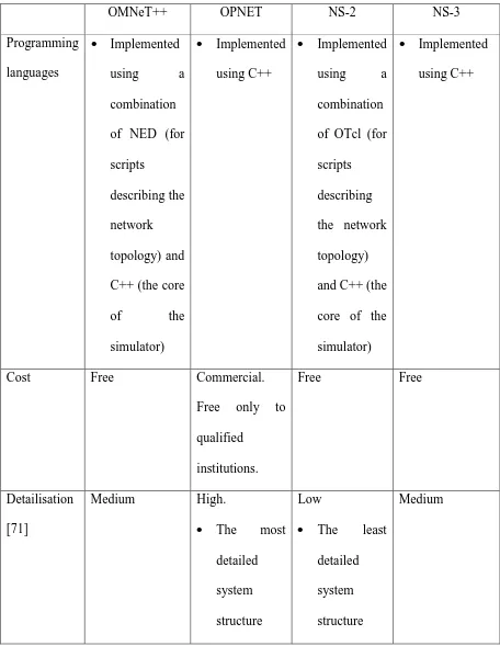
a brief description of the study and comparison of various simulation software before selecting
the software deemed most suitable for performing the LTE simulation. The software selected is
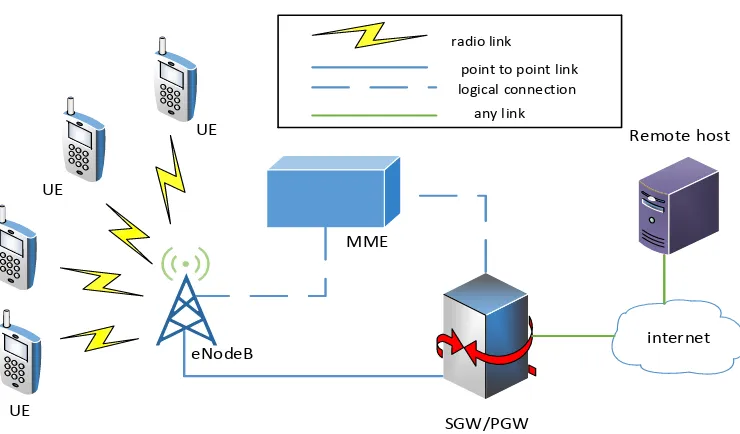
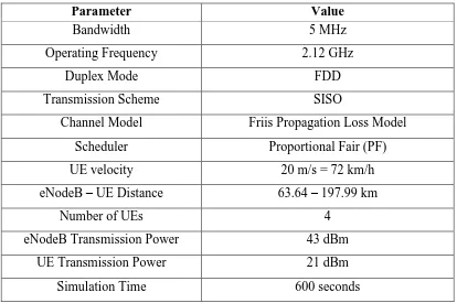
NS-3 and MATLAB. The software will be used for the baseline LTE simulation model based
on the described topology to be developed and simulated for various distances between the
eNodeB and the UEs for both uplink and downlink transmissions. Several important output
performance parameters including user throughput and SINR values, focusing only on the video
streaming application, are recorded before relevant graphs are plotted. Finally, the chapter
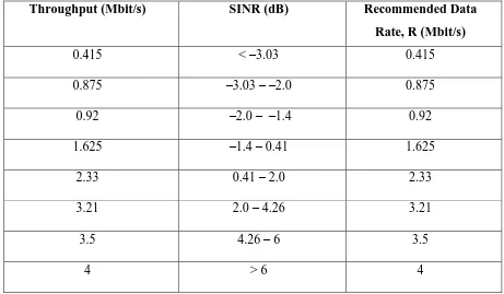
introduces a summary determining the correlation between the measured SINR and its
corresponding throughput.
Chapter 4 discusses the development of the content-aware RRM model resulting from
the correlation between the measured SINR and its throughput hypothesised as presented in
Chapter 3. Cross-layer optimisation for LTE system using a look-up table is proposed in which
the video data rates can be dynamically adjusted depending on the measured SINR on either
side of the communications link. Extensive simulations are conducted for three different UE
velocities for both uplink and downlink transmissions to evaluate the effectiveness of the
proposed model and the baseline model.
Chapter 5 discusses in detail the practical investigation activities undertaken at Rinicom
Ltd to perform the practical comparisons with the theoretical simulation models developed in
Chapters 3 and 4. Since the LTE infrastructure is not available at the company due to the
spectrum licensing requirement by the OFCOM, UK, the simulation scenarios are emulated
26
support to the overall LTE emulation activities to serve as the LTE platform. Two experiments
are conducted during the emulation process in which the first experiment is to correlate the
measured SINR and the corresponding throughput for the baseline model in the uplink with the
one obtained in Chapter 3. The second experiment is to compare the performance of the
proposed CARRMa model developed in Chapter 4, also in the uplink. The results obtained from
both experiments are then presented and analysed. Lastly, Chapter 6 provides overall
27
2
RADIO RESOURCE MANAGEMENT IN LTE/LTE-ADVANCED
SYSTEM
Since the initial release of the LTE Release 8 standard in 2008, some improvements and
amendments have been added to meet the IMT-Advanced requirements recommended by the
ITU. The limitations of the first version were overcome in subsequent releases of the standard
in which carrier aggregation is implemented to achieve up to 100 MHz transmission bandwidths
[12 - 13]. Besides the bandwidth requirement, it is useful to note that the demanding targets of
4G systems regarding QoS and data rates can only be achieved with effective Radio Resource
Management (RRM). In this chapter, an overview of the LTE Release 10 (LTE-Advanced)
standards and system architecture are provided, beginning with the evolution of the standards
which is next followed by the description of the LTE system in which the work in this thesis is
based upon. The previous and current research interests in RRM for those systems are also
highlighted in this chapter.
2.1 Introduction
Currently, the ITU is working to enhance the system requirements for next-generation
mobile communication systems called IMT-Advanced and beyond. The IMT-Advanced
systems are mobile broadband communication systems which include new capabilities that go
far beyond those of the IMT-2000 family of systems such as wideband code division multiple
access (WCDMA) or WiMAX and LTE. The main reason why the ITU has introduced
IMT-Advanced is to enhance the capability of prior technology and to eliminate the limitations in
existing communication networks to provide a much higher level of service. The performance
of IMT-Advanced will support low to high mobility of applications; 100 Mbit/s for high and 1
28
In response to the recommendations proposed by the ITU, 3GPP has proposed ‘Long
Term Evolution’ which is the name provided to the new standard developed by 3GPP to meet
the enormous market demands for throughput. LTE is the next evolution of 2G, and 3G systems
and the performance level of the system is expected to be on par with those of current wired
networks.
The LTE/EPC standardisation project commenced in December 2004 by the 3GPP RAN
working groups to develop a feasibility study for an evolved UTRAN and for all IP-based EPC.
The initial phase of the project was called the ‘Study Item’ phase. In December 2007, the
specifications for all LTE functions were completed while the specifications for the EPC
functions achieved significant milestones for interworking with 3GPP and CDMA networks.
Subsequently, in 2008, the 3GPP working groups hastened to complete all protocol and
performance specifications where the groups finally completed the tasks by December 2008
with Release 8 being made available [17].
LTE is a radio access technology based on Orthogonal Frequency Division Multiplexing
(OFDM), with conventional OFDM on the downlink and single carrier frequency division
multiplexing (SC-FDM) or more specifically, discrete Fourier transform spread OFDM
(DFTS-OFDM) [18] on the uplink. The purpose of having a different type of radio interface on the
uplink is because SC-FDM can reduce terminal power consumption, allowing for a more
efficient power-amplifier operation. Also, equalisation in conventional OFDM can efficiently
eliminate the inter-symbol-interference (ISI) problem in the received signal [19].
29
In any cellular network, the network functions can be divided into two parts: the radio
access network part and the core network part. Functions such as modulation, handover and
header compression are part of the access network, while other functions such as mobility
management and charging, are part of the core network. In LTE, the radio access network is
called E-UTRAN, and the core network is called EPC [17] as shown in Figure 2.1.
Radio Access Network: E-UTRAN, the radio access network of LTE, supports all
services including real-time over shared packet channels. Consequently, by using packet access,
better integration among all multimedia services, wireless and fixed services can be achieved.
The central philosophy behind LTE is to reduce the number of nodes, which as a result, LTE
developers then decided to adopt single-node architecture. Given this decision, the previous
node in the WCDMA/HSPA radio access network, namely the Radio Network Controller
(RNC), is merged with its Node B, thereby leading to higher complexity for the new base station
in LTE, called eNB (Enhanced Node B). Since the eNBs are fast becoming more complicated
than their predecessor (UTRAN), additional tasks and functionalities can now be performed,
including radio resource management functions.
Core Network: The new core network is the result of the radical evolution of
third-generation systems which cater for the packet-switched domain only. Therefore, a new name is
given, the Evolved Packet Core (EPC). Similar philosophy towards the LTE radio access
network is applied again to its core network, which results in minimising the number of nodes.
The EPC splits the user data flows into data and control planes. For each plane, a specific node
is defined together with the generic gateway that links the LTE network to external networks
such as the internet and other systems.
30
(i) The MME (Mobility Management Entity): is responsible for processing
signalling messages in the control plane and to manage the connections for
subscribers.
(ii) The Serving Gateway: acts as the router to other 3GPP technologies and
serves as the packet data interface for E-UTRAN.
(iii) The PDN Gateway (Packet Data Network): is the router to the Internet and
hence, the termination point for the sessions towards the external packet data
network.
(iv) The PCRF (Policy and Charging Rules Function): supports the
policy-making process and manages tariff charges for all subscribers.
Internet
PDN GW
S5 interface
S1 interface
X2 interface eNB
[image:31.612.171.454.375.649.2]MME/Serving GW
31
Figure 2.2 illustrates the basic protocol structure of LTE. Some of the tasks that are
performed by both the radio link control (RLC) and the medium access control (MAC) layers
are related to data flow multiplexing and retransmission handling. In the physical layer, a series
of processes occur before the information data is ready to be transmitted. The data is first turbo
coded and then, modulated using one of the following modulation techniques: quadrature-phase
shift keying (QPSK), 16-QAM, or 64-QAM, followed by OFDM modulation. The OFDM
subcarrier spacing is set at 15 kHz. To prevent the problem of multi-path delay spread, two
different cyclic-prefix lengths are employed in both the downlink and uplink. For most
scenarios, a normal cyclic prefix length of 4.7 µs is used whereas, for highly dispersive
environments, an extended cyclic prefix length of 16.7 µs is used, instead.
In the downlink, distinct types of multi-antenna processing are applied, preceding the
OFDM modulation. Also, cell-specific reference signals are transmitted in the downlink to
perform channel estimation and measurements for several reasons including coherent
demodulation, mobility management and channel state information. The LTE transmitted signal
is built upon multiple 1-ms duration subframes in which each subframe comprises of 12 or 14
OFDM symbols, depending on which type of cyclic prefix is used. Figure 2.3 illustrates the
formation of a radio frame by cascading ten subframes together. As a result, of the 1 ms short
subframe duration, small delays are unavoidable for both the user data and the control signals
which include the hybrid automatic repeat-request (ARQ) feedback and channel-quality
feedback from the user terminals to the eNB. One distinct feature of the downlink and uplink
protocol, as shown in Figure 2.2, is the presence of DFT precoder only in the uplink
transmission. This DFT precoder is used preceding the OFDM modulator to produce SC-FDM
32
Segmentation, ARQ
Multiplexing
Hybrid ARQ
Coding, rate matching
Modulation
DFT
Antenna mapping OFDM modulation MAC
PHY RLC
Sc
h
ed
ul
er
Uplink only Payload selection
Priority handling, payload selection
Retransmission control
Code rate
Modulation scheme
Antenna and resource assignment
[image:33.612.140.491.68.496.2]Data flows
Figure 2.2: Basic LTE protocol structure [20]
LTE can operate in both Frequency Division Duplex (FDD) and Time Division Duplex
(TDD) modes as depicted in Figure 2.3. Even though the time domain representation is mostly
the same for both duplex modes, one of the most significant differences between the two, is the
existence of a unique subframe in the TDD mode. The purpose of this particular subframe is to
33
In the case of FDD, two carrier frequencies are allocated for its operation, one for
downlink transmission (fDL) and one for uplink transmission (fUL). In each transmission, ten
subframes are cascaded together to form the radio frame in which both the uplink and the
downlink transmissions can occur simultaneously within a cell.
In the case of TDD, only one single carrier frequency is present, and hence, the downlink
transmissions are continuously alternating with the uplink transmissions to avoid colliding with
each other in the same cell. As FDD requires a guard band between the two uplink and downlink
frequency bands, the TDD however, requires a guard period for its operation. It is realised by
splitting one or two of the ten subframes in each radio frame into three special fields, namely a
Downlink Pilot Time Slot (DwPTS), a guard period and an Uplink Pilot Time Slot (UpPTS).
The function of the downlink field, DwPTS is the same as any other downlink subframe whereby
data transmission can be performed using this field. The uplink Pilot Time Slot (UpPTS),
however, is usually used for channel sounding purposes and connection requests by user
terminals.
Despite the significant differences between the FDD and TDD modes mentioned earlier,
it is worth noting at this juncture, that all baseband processing is virtually identical for both
duplex modes, making it possible to develop low-cost terminals supporting both FDD and TDD
operation modes [6], [19].
34
FDD
TDD
UL
DL
UL
DL
fUL
fDL
fDL/fUL
Subframe #0 #1 #2 #3 #4 #5 #6 #7 #8 #9
One radio frame, Tframe = 10 ms
One subframe, Tsubframe = 1 ms
(Special subframe)
DwPTS
GP UpPTS
[image:35.612.102.524.71.273.2](Special subframe)
Figure 2.3: LTE frame structure [6] [19]
2.3 LTE-Advanced Architecture and Protocol Stack
LTE Release 10 was finalised towards the end of 2011 by 3GPP which conforms to the
IMT-Advanced specifications. Currently, the LTE Release 11, 12, 13 and 14, that are the
enhancements to the previous completed LTE Release 10 specification are being researched to
provide better performance. The capability of LTE-Advanced is highly recommended by 3GPP
because it can support transmission bandwidths up to 100 MHz and increases the capacity of
the UE during transmission and reception processes [1], [13], [22]. This is in line with the
objectives of the targets set for IMT-Advanced, which are higher data rates, improved coverage,
better QoS performance and equality for all users. Also, it is further capable of providing support
for positioning services, broadcast/multicast services and enhanced emergency-call
functionality [5], [16]. Figure 2.4 shows the E-UTRAN architecture for LTE-Advanced, which
complies with the IMT-Advanced specifications. The most important and the only available
35
the base station in LTE, that provides the air interface for the UE by establishing communication
links through the user plane and control plane termination protocols. Each eNB can control one
or more E-UTRAN cells and can also interconnect with its adjacent eNBs through the X2
interface. Also, lower-cost Home eNBs (HeNBs also known as femtocells), that are introduced
primarily to improve indoor coverage can be linked up with the EPC directly or via a gateway
where more HeNBs can be further supported [23]. Furthermore, 3GPP is also proposing further
strategies to enhance network performance by applying relay nodes.
As mentioned earlier, eNBs provide the E-UTRAN with the necessary user and control
plane termination protocols. Figure 2.5 displays a graphical representation of both protocol
stacks. In the user plane, the related protocols consist of the Packet Data Convergence Protocol
(PDCP), the Radio Link Control (RLC), Medium Access Control (MAC), and the Physical
Layer (PHY) protocols. The control plane stack, however, has an additional protocol, namely,
36
P-GW
S-GW
MME
EPC
E-UTRAN
HeNB-GW
S1 S1-U
X2
eNB
eNB S1-MME
[image:37.612.123.511.77.325.2]Relay Node
Figure 2.4: LTE-Advanced E-UTRAN architecture [23]
PDCP RLC MAC
PHY RRC
eNB
User Plane Control
Plane
[image:37.612.190.439.389.651.2]37
2.4 eNodeB Protocol Stack and RRM Functions
Radio Resource Management (RRM) is one of the key components of the OFDMA
modulation technique in a wireless system. RRM is the system level control of co-channel
interference and other radio transmission characteristics in wireless communication systems, for
example, in cellular networks such as LTE, wireless networks and broadcasting systems [16]. It
can also be defined as a control mechanism for the entire system used to manage radio resources
in the air interface within a cellular network [16], [28]. Both LTE and LTE-Advanced
technologies implement resource management to ensure that the process of data transmission
and reception are carried out efficiently. Basically, RRM analyses several factors such as traffic
load, interference, noise and coverage to produce efficient data transmission and high capacity.
RRM functions should further consider the constraints imposed by the radio interface to make
decisions regarding the configuration of different elements and parameters influencing air
interface behaviour [16]. As in the case of the LTE/LTE-Advanced system, all RRM functions
occur in the eNodeB such as transmission power management, mobility management and radio
resource scheduling [29].
Figure 2.6 illustrates the user plane and control plane protocol stack at the eNodeB with
the mapping of the primary RRM functions to the corresponding layers [30 - 31]. The user plane
protocol at the eNodeB incorporates the packet data convergence protocol (PDCP) at layer 3,
followed by the radio link control (RLC) and the medium access control (MAC) protocols at
layer 2. One of the RLC functions is to provide an outer ARQ mechanism, whereas the MAC
function involves asynchronous hybrid ARQ. It is possible for the outer ARQ and hybrid ARQ
functions to closely interact with each other for additional performance optimisation since both,
RLC and MAC are in the same layer. The PDCP function manages each data flow, also called
38
terminated at the eNodeB, with the radio resource control (RRC) serving as the main function
at layer 3.
There are various RRM functions at the eNodeB which can be exploited from layer 1 to
layer 3 as shown in Figure 2.6. At layer 3, the related RRM algorithms such as admission
control, QoS management and semi-persistent scheduling, are defined as semi-dynamic
mechanisms. Usually, they are implemented during the setup of new data flows or during
non-frequent reconfigurations. A different situation for layers 1 and 2 exists, however, because the
RRM functions are more dynamic as new decisions need to be made at every transmission time
interval (TTI) of 1 ms.
The physical layer (PHY) of the eNodeB is based on OFDMA, applying the shared
channel concept for unicast data transmission which is like IEEE 802.16 (WiMAX). Figure 2.7
illustrates the PHY time-frequency resource space representation for one TTI or duration of 1
ms. Each TTI possesses 14 OFDM symbols if the default configuration with a short cyclic prefix
is assumed [32]. In each downlink TTI, data transmission and control information are
multiplexed at the same time, where the first 1 to 3 OFDM symbols in a TTI are reserved for
downlink control channels such as the physical control format indicator channel (PCFICH) and
the physical downlink control channel (PDCCH). The PCFICH determines the time duration of
the control channel space (1 – 3 OFDM symbols), while the PDCCH transports the dynamic
scheduling grants for both downlink and uplink. The remaining OFDM symbols within the TTI
can be used for transmitting common or dedicated reference signals and more importantly, user
data. The PDCCH also carries information on the used modulation and coding scheme and the
user’s frequency domain allocation indicator, etc. The combination of the allocated resources
39
block size. With this information, the user can demodulate and decode the transport blocks
transmitted by the eNodeB.
In the frequency domain of the TTI, the resources are separated into equally-sized
physical resource blocks (PRBs). Each PRBs contains 12 subcarriers, which is equivalent to a
180-kHz bandwidth, with a subcarrier spacing of 15 kHz [32]. The number of PRBs can be
varied depending on various system bandwidth configurations (e.g. 25, 50 and 100 PRBs for
system bandwidths of 5, 10 and 20 MHz, respectively). There are several reference symbols
(also called pilots) allocated on the subcarrier symbols to provide reliable channel estimation at
the mobile terminal, even though these are not shown in Figure 2.7. The data transmission in
the downlink path is dependent on fast link adaptation by varying the modulation technique
from quadrature phase shift keying (QPSK) to 64-quadrature amplitude modulation (64-QAM),
assuming the transmit power of the PRBs for a user are equal and constant. This is in contrast
to the PDCCH transmission where a fixed modulation (QPSK) is used, together with variable
coding and dynamic power control to achieve sufficient reliability.
In Figure 2.6, the sole responsibility of the channel quality indicator (CQI) manager is
to process received CQI reports from active users in the cell, which are later used for scheduling
decisions and link adaptation purposes. The CQI feedback configurations can be carried out as
follows:
Measuring a wideband channel quality;
Separate reporting for some subbands; and
Reporting of the average channel quality of the best M subbands [33]. A sub-band, in
this case, comprises k contiguous PRBs, in which the k and M values are determined by
40
The first two configurations are used for selective frequency measurements, which are
useful for the frequency domain packet scheduler (FDPS). CQI feedback may be configured
periodically and requested by the eNodeB explicitly when scheduling a specific user in the
uplink. Admission control QoS Management Semi-persistent scheduling Hybrid ARQ manager Dynamic
scheduling Link adaptation
PDCCH
adaptation CQI manager
RRC
RLC
MAC
PHY Control plane
User plane RRM functions
[image:41.612.85.541.183.385.2]RRC RLC MAC PHY Layer 3 Layer 2 Layer 1
Figure 2.6: Overview of the eNodeB user plane and control plane architecture and the mapping of the primary RRM functions to the different layers [30]
Layer 1 and layer 2 control channels (e.g., PDCCH and PCFICH)
Up to 3 OFDM symbols
Block with 12 subcarriers x K OFDM symbols
Block with 12 subcarriers x K OFDM symbols
Block with 12 subcarriers x K OFDM symbols
One TTI = 1 ms (14 OFDM symbols)
PRB #1 PRB #2 PRB #N Sy ste m b an dw id th Time dimension Data space
[image:41.612.126.521.443.673.2]41
2.4.1 Dynamic RRM Features (QoS Parameters, Admission Control and Semi-Persistent Scheduling)
All semi-dynamic RRM functionalities such as QoS management, admission control and
semi-persistent scheduling) are operated in layer 3 of the eNodeB’s control plane as depicted in
Figure 2.6. In the case of QoS management, each data flow (or bearer) is associated with a QoS
profile containing the following downlink related parameters [34]:
Guaranteed bit rate (GBR).
Allocation retention priority (ARP).
QoS class identifier (QCI).
The GBR parameter is specified only for GBR bearers while the parameter for non-GBR
bearers is defined by an aggregate maximum bit rate. The ARP parameter is mainly related to
priority settings when handling admission control decisions. The parameter is specified as an
integer between 1 and 16. The QCI parameter acts as an indicator of a more detailed set of QoS
attributes listed in Table 2.1. Such QCI parameters are the layer 2 packet loss rate and the packet
delay budget. The information contained in both parameters can be used by the eNodeB to adjust
the outer ARQ mechanism in the RLC layer, and the layer 2 packet delay budget can also be
used by the packet scheduler in the eNodeB when prioritising specific queues to achieve the
head-of-line packet delay targets.
Based on the QoS profile, the admission control function may decide whether to grant
or reject radio or network access requested by new bearers in the cell. Some considerations
might be considered by the admission control algorithm before decisions are made such as the
current resource condition in the cell, the new bearers’ QoS requirements, the related priority
level and the present QoS level attained by active users in the cell. The situation where a new
42
QoS level of the currently active users in the cell having the same or higher priority as discussed
in [35].
The fundamental semi-persistent scheduling principle in layer 3 is to allocate certain
transmission resources periodically for a specific user or bearer. This is undertaken by the RRC
protocol whereby a specific timing pattern is initially configured for the semi-persistent
scheduled resources. The semi-persistent scheduling method represents regular scheduling of a
fixed data amount, which is the reason why it is mainly intended for deterministic data flows
43
Table 2.1: QCI levels in LTE QoS profile [34]
QCI Number
Resource
Type Service Priority Layer 2 Packet Delay (ms) Layer 2 Packet
Loss Rate Applications
1
Guaranteed Bit Rate
(GBR)
2 100 10−2 Conversational voice
2 4 150 10−3 Conversational video (live
streaming)
3 3 50 10−3 Real-time gaming
4 5 300 10−6 Non-conversational video
(buffered streaming) 5 Non-Guaranteed Bit Rate (Non-GBR)
1 100 10−6 IMS (IP multimedia subsystem) signalling
6 6 300 10−6
Video (Buffered Streaming), TCP, Web, e-mail, chat, file
sharing, etc.)
7 7 100 10−3 Voice, Video (Live Streaming), Interactive Gaming
8 8 300 10−6 Video (Buffered Streaming),
TCP, Web, e-mail, chat, file sharing, etc.)
9 9 300 10−6
2.4.2 Fast Dynamic RRM Algorithms
The most important RRM entity at layer 2 is the dynamic packet scheduler (PS), which
decides on resource scheduling by allocating PRBs every TTI to the users. It also performs link
adaptation whereby a suitable modulation and coding scheme is assigned to the users,
accordingly. The allotted PRBs and selected modulation and coding scheme are then transmitted
to the targeted users using the PDCCH. The final objective of the scheduling mechanism is to
maximise cell capacity, and concurrently, maintaining the minimum QoS requirements for the
bearers while ensuring adequate resources are available for best-effort bearers which do not
require strict QoS requirements [36]. It is important to note at this point, that scheduling
decisions are decided on a per-user basis although a user may have one or more data flows. In a
44
protocol governs one data flow in the control plane, and one or more data flows that are to be
used in the user plane. The MAC protocol determines the amount of data to be transmitted from
each data flow, depending on the transport block size scheduled for a certain user. The packet
scheduler and the hybrid ARQ manager need to interact closely with each other as the former is
also responsible for scheduling retransmissions. This is because in one TTI, the packet scheduler
is not allowed to schedule both a new transmission and a pending hybrid ARQ transmission to
a scheduled user at the same time, and therefore, must decide between the two transmissions
making sure that the minimum QoS requirements are preserved. The link adaptation unit further
assists the packet scheduler by relaying information on the supported modulation and coding
scheme for a user based on the selected set of PRBs. The information provided by the link
adaptation is decided based mainly upon the CQI feedback received from the users in the cell
and the QoS requirements.
2.5 Research on RRM for LTE
In recent years, RRM techniques have undergone extensive research to cater for the large
targets in IMT-Advanced with the objectives of optimising network performance
(network-centric), maintaining QoS requirements (user-centric) and providing fairness (equity) for all
users. Depending on the ultimate objective established by network operators, Radio Resource
Allocation (RRA) algorithms, which are part of the RRM, can also be designed to be
fairness-oriented or by providing a trade-off between fairness and throughput [37]. For example, the
Resource Allocation (RA) algorithm introduced in [38] provides a balance between efficiency
and fairness which optimises system performance while producing improved performance, to
guarantee the user’s QoS requirement in a heterogeneous traffic condition. Several common
45
and admission control and the most important, for scheduling [29], [39].
In wireless communication, scheduling plays a significant role in determining system
performance such as the throughput, delay, jitter, fairness and loss rate [40 - 41]. Being different
from wired cases, scheduling in LTE networks needs to consider unique characteristics such as
the location-dependent channel status. It is well acknowledged that packet scheduling (PS),
which is one of the core functionalities for radio resource management, is an essential element
to enhance the performance of an LTE system. In efficiently utilising scarce radio resources,
different PS algorithms, as a result, have been proposed and deployed.
In [42], a new packet scheduling (PS) framework called the adaptive time domain
scheduler, with built-in congestion control has been added to existing conventional QoS aware
PS algorithms for the LTE-Advanced downlink transmission. This framework optimises
multi-user diversity in both time and frequency domains by jointly considering the channel condition,
queue status and QoS feedback. Eventually, this technique improves QoS of real-time (RT)
traffic and a fair share of radio resources to non-real time (NRT) traffic.
The authors, in [39], have proposed a new modified-proportional fair scheduler to further
improve the throughput and spectral efficiency of an LTE system. Conceptually, the new
scheduler divides a single subframe into multiple time slots and allocates the RBs to the targeted
UE in all time slots for each subframe based on the instantaneous CQI feedback from the UEs.
In that sense, no UEs will be left out of the scheduling process in all time slots. For the overall
performance, the Modified-PF scheduler outperforms Round Robin (RR) and PF schedulers by
almost 92 % of the RR throughput and significantly boosts the PF throughput by 10 %.
It is normal for each user to expect high throughput to enjoy various multimedia and
data services regardless of their location and mobility. However, in cellular architecture, if a
46
poor spectral efficiency as compared to the MSs that are near to the base station (BS). By virtue
of Adaptive Modulation & Coding (AMC) which is one of the resource allocation techniques
for the OFDMA system, it will select the lowest-order modulation scheme and high coding rate
to maintain the link quality without increasing the signal power. Channel gain is obtained
through multiuser diversity in which the BS will focus its communication with the nearby MSs
having good channel condition. As a result, to satisfy the ‘victimised’ user’s QoS requirement,
an effortless way to solve the problem is by deploying relay stations (RSs) which can assist in
data delivery. Many researchers have studied the advantages of deploying fixed relay stations
in cellular architecture [43 - 44]. The relay stations can overcome the need for high transmission
power and concurrently, can transmit at high forwarding data rates inside the BS remote areas
while network infrastructure is minimally maintained. Due to this reason, the relaying system
was chosen to maximise the uplink and downlink system throughput and its ability to relay
information from the BS to the user to, thereby, improve system performance [13], [45].
However, as mentioned in [46], RS has a drawback whereby it consumes additional resources
as compared to using the direct path. As a result, the signalling overhead for the relay
communication will increase, which will naturally reduce the throughput gain. To some extent,
delay-sensitive services such as video streaming and video gaming will be adversely affected
due to the longer paths the signals need to travel [13]. Consequently, improved RRM techniques
need to be developed to manage these issues.
Another RRA technique which focuses on network throughput is implemented in [47].
The strategy, known as the interference-aware RRM scheme, re-examines the system
interference dynamics for a given sub-channel assignment to improve system throughput. It
adopts 2-level optimisation as performed in [38] where subchannel allocation is followed by
47
perspective, the new proposed scheme appends the basic Water Filling Algorithm (WFA) which
results in the enhancement over the basic WFA and at the same time, power allocation
calculations are also modified to achieve better throughput.
2.6 Cross-Layer Design for LTE
Cross-layer design for achieving the desired performance in wireless networks is not a
new area of research and started when wireless communication became more and more
attractive to implement especially in remote areas where fixed-line communication was
expensive to deploy. Although it may appear that the concept itself is violating the philosophy
around the layering concept in networking, the complex issues related to wireless environments
such as time-varying channels and propagation loss, suggests the need for cross-layer design to
be considered.
Most of the cross-layer designs for radio resource management as in [48 - 49] involve
the interactions between the MAC layer and the PHY layer, wherein the MAC layer, proper
scheduling techniques are carried out based on specific QoS requirements for each user or data
bearer depending on the channel state information feedback from the PHY layer. One interesting
technique is shown in [50] where the cross-layer optimisation technique does not require CQI
information to be fed back from the user’s side. The real-time video packet transmission is
undertaken by adapting the sent bit rate automatically, according to the estimated packet loss
due to the expiration of the packet delay deadline based on queuing analysis by considering both
the packets queuing delay and transmission delay. Ironically, this technique has somewhat
deviated from the 3GPP standards which require the eNodeB to monitor the channel condition
of each user continually.
![Figure 2.1: LTE Release 8 architecture [17]](https://thumb-us.123doks.com/thumbv2/123dok_us/9371010.439727/31.612.171.454.375.649/figure-lte-release-architecture.webp)
![Figure 2.2: Basic LTE protocol structure [20]](https://thumb-us.123doks.com/thumbv2/123dok_us/9371010.439727/33.612.140.491.68.496/figure-basic-lte-protocol-structure.webp)
![Figure 2.3: LTE frame structure [6] [19]](https://thumb-us.123doks.com/thumbv2/123dok_us/9371010.439727/35.612.102.524.71.273/figure-lte-frame-structure.webp)
![Figure 2.5: Protocol stack [23]](https://thumb-us.123doks.com/thumbv2/123dok_us/9371010.439727/37.612.123.511.77.325/figure-protocol-stack.webp)
![Figure 2.7: The downlink physical layer resource space for one TTI [30]](https://thumb-us.123doks.com/thumbv2/123dok_us/9371010.439727/41.612.85.541.183.385/figure-downlink-physical-layer-resource-space-tti.webp)
![Table 2.1: QCI levels in LTE QoS profile [34]](https://thumb-us.123doks.com/thumbv2/123dok_us/9371010.439727/44.612.90.555.91.382/table-qci-levels-in-lte-qos-profile.webp)