polymers
Article
Mechanically Enhanced Electrical Conductivity of
Polydimethylsiloxane-Based Composites by a Hot
Embossing Process
Xiaolong Gao1 , Yao Huang2, Xiaoxiang He1,*, Xiaojing Fan1, Ying Liu1,2, Hong Xu1, Daming Wu1,2,* and Chaoying Wan3,*
1 College of Mechanical and Electrical Engineering, Beijing University of Chemical Technology, Beijing 100029,
China; [email protected] (X.G.); [email protected] (X.F.); [email protected] (Y.L.); [email protected] (H.X.)
2 State Key Laboratory of Organic-Inorganic Composites, Beijing University of Chemical Technology,
Beijing 100029, China; [email protected]
3 International Institute for Nanocomposites Manufacturing (IINM), WMG, University of Warwick,
Warwich CV4 7AL, UK
* Correspondence: [email protected] (X.H.); [email protected] (D.W.); [email protected] (C.W.)
Received: 30 November 2018; Accepted: 25 December 2018; Published: 2 January 2019
Abstract:Electrically conductive polymer composites are in high demand for modern technologies, however, the intrinsic brittleness of conducting conjugated polymers and the moderate electrical conductivity of engineering polymer/carbon composites have highly constrained their applications. In this work, super high electrical conductive polymer composites were produced by a novel hot embossing design. The polydimethylsiloxane (PDMS) composites containing short carbon fiber (SCF) exhibited an electrical percolation threshold at 0.45 wt % and reached a saturated electrical conductivity of 49 S/m at 8 wt % of SCF. When reducing the sample thickness from 1.0 to 0.1 mm by the hot embossing process, a compression-induced percolation threshold occurred at 0.3 wt %, while the electrical conductivity was further enhanced to 378 S/m at 8 wt % SCF. Furthermore, the addition of a second nanofiller of 1 wt %, such as carbon nanotube or conducting carbon black, further increased the electrical conductivity of the PDMS/SCF (8 wt %) composites to 909 S/m and 657 S/m, respectively. The synergy of the densified conducting filler network by the mechanical compression and the hierarchical micro-/nano-scale filler approach has realized super high electrically conductive, yet mechanically flexible, polymer composites for modern flexible electronics applications.
Keywords:electrical conducting network; forced assembly; compression-induced percolation threshold; hybrid filler; synergy
1. Introduction
The development and popularity of smart electronics have attracted increasing demands for high performance and mechanically flexible electrically conducting polymer composites. Intrinsic electrical conducting polymers, such as polypyrrole, polyaniline, polyacetylene, and polythiophene, have the constraints of unstable conductivity, insolubility, difficulty of processing, small-scale, and high cost. Electrically conducting polymer composites can be prepared by incorporating conductive fillers into an insulating polymer matrix and provides the advantages of ease of processing and an ability to tailor the electrical properties based on composite architecture [1–6]. The electrical conductivity of polymer composites relies on the nature of the conductive fillers and the formation of a continuous and percolated conducting pathway in the insulating polymeric matrix [7–11]. The dispersion of conducting
fillers such as carbon nanotubes (CNTs), carbon fibers, graphene, and carbon black, in a polymer matrix have been improved by using in situ polymerization [12] or forming segregated microstructures under specific processing conditions [13]. It has been reported that multi-walled CNTs formed a segregated and percolated conductive network structure in poly (phenylene sulfide) matrix by using solid-mixing and subsequent melt-compression. A percolation threshold as low as 0.33 wt % of CNTs was obtained, and the electrical conductivity of the composites was increased from∼10−10S/cm to∼0.11 S/cm with the use of CNT contents up to 10 wt %.
The electrical percolation threshold and electric conductivity of polymer composites are highly dependent on the properties of the conducting fillers, their dispersion, and interfacial interactions between the filler particles and the polymer matrix [14–19]. A good dispersion of graphene oxide (GO) was achieved in polyamide-6 (PA6) composites by in situ polymerization, which facilitated the formation of an electrically conductive network and resulted in significantly improved electrical conductivity of the composite [12]. A PA6/polypropylene (PP)/CNT (20/80/4) composite exhibited a high electrical conductivity in comparison with the PA6/PP/CNTs (50/50/4) composite due to the selectively localized CNT in the PA6 phase in forming a compact conductive network [20]. In addition, a synergistic effect between graphene and CNTs in a thermoplastic polyurethane matrix led to a reduced percolation threshold, where the graphene acted as a ‘spacer’ to separate the entangled CNTs from each other and the CNT bridged the gap between individual graphene sheets. Such an effect was beneficial for the dispersion of the CNTs and the formation of effective conductive paths, leading to improved electrical conductivity at a lower conductive filler content [21]. As to conductive flexible polydimethylsiloxane (PDMS) composites, Sethi prepared elastomeric composites by incorporating various carbon blacks in insulating PDMS matrix. The results showed that alternating current (AC) and direct current (DC) conductivity increased with an increase in some bending flex cycles, and with compressive flexing, DC conductivity initially dropped but later started increasing with an increase in flex cycles [22]. Moreover, to address the challenge of flexible materials with a relatively high electrical conductivity and a high elastic limit, Wu reported a new and facile method to prepare porous polydimethylsiloxane/carbon nanofiber composites by using sugar particles coated with carbon nanofibers (CNFs) as the templates. The resulting three-dimensional porous nanocomposites, with the CNFs embedded in the PDMS pore walls, exhibit a greatly increased failure strain (up to∼94%) compared to that of the solid, neat PDMS (∼48%) [23]. More related research on flexible PDMS can be found in References [24–28].
Polymers2019,11, 56 3 of 14
2. Experimental
2.1. Materials
PDMS with a trade name of SYLGARD 184, obtained from DOW CORNING (Midland, MI, USA), was used as the polymer matrix. As a micro-scale filler; short carbon fibers (SCF) of 5–10µm in diameter and 3–5 mm in length were provided by Toray, Japan. As nano-scale filler; graphene, carbon black, and CNTs were used. Few-layer graphene (G) of 1.0–1.77 nm in thickness and 10–50µm in width was provided by Changzhou Sixth Element Material Technology Co., Ltd. (Changzhou, China). Superconductive carbon black (CCB, BP2000) with a particle size of 15 nm was obtained from CABOT (Boston, MA, USA). CNTs with 20–30 nm diameter and 10–30µm length were provided by Beijing Daoking Technology Co., Ltd. (Beijing, China). The electrical conductivity of the four fillers (SCF, G, CCB, and CNT) were ~ 2.6×10⁴S/m, 1.0×10⁵S/m, 5.0×10⁴S/m, and 1.0×10⁴S/m, respectively.
2.2. Composite Preparation and SCFNA Process
A conical twin-screw compounder of HAAKE MiniLab combined with a specifically designed hot embossing device was used for preparation of the PDMS composites in order to realize a spatially confined forced assembly network (SCFNA) of conductive fillers.
For PDMS/SCF composites, the PDMS was mixed with the short carbon fibers at weight ratios of 0.5, 1, 1.5, 2, 3, 4, 6, or 8 wt % at 25◦C with a rotational speed of 70 rpm for 10 min. For the preparation of PDMS composites containing hybrid micro- and nano-scale fillers, 1 wt % of CNT, G, or CCB was included to the above PDMS/SCF compound with a rotational speed of 50 rpm for an additional 10 min at 25◦C to obtain PDMS/SCF-CNT, PDMS/SCF-G, or PDMS/SCF-CCB composites.
The experimental hot embossing device as shown in Scheme1a provided a pressing force up to 10 MPa with a pressing speed of 0.005 to 0.5 mm/s in a working stroke. The servo motor of this embossing device was accurately controlled by a programmable logic controller (PLC) system and the position accuracy of±3µm for the up platen was guaranteed. The compressing mold was made of two flat plates with electrical heaters. The temperature of the molds was controlled from ambient temperature to 350◦C with a control accuracy of±1◦C and heating rate of 15◦C/min. The effective working area was 210 mm×300 mm.
Polymers 2019, 11, x FOR PEER REVIEW 3 of 14
PDMS with a trade name of SYLGARD 184, obtained from DOW CORNING (Midland, MI, USA), was used as the polymer matrix. As a micro-scale filler; short carbon fibers (SCF) of 5–10 μm in diameter and 3–5 mm in length were provided by Toray, Japan. As nano-scale filler; graphene, carbon black, and CNTs were used. Few-layer graphene (G) of 1.0–1.77 nm in thickness and 10–50
μm in width was provided by Changzhou Sixth Element Material Technology Co., Ltd. (Changzhou, China). Superconductive carbon black (CCB, BP2000) with a particle size of 15 nm was obtained from CABOT (Boston, MA, USA). CNTs with 20–30 nm diameter and 10–30 μm length were provided by Beijing Daoking Technology Co., Ltd. (Beijing, China). The electrical conductivity of the four fillers (SCF, G, CCB, and CNT) were ~ 2.6 × 10⁴ S/m, 1.0 × 10⁵ S/m, 5.0 × 10⁴ S/m, and 1.0 × 10⁴ S/m,
respectively.
2.2. Composite Preparation and SCFNA Process
A conical twin-screw compounder of HAAKE MiniLab combined with a specifically designed hot embossing device was used for preparation of the PDMS composites in order to realize a spatially confined forced assembly network (SCFNA) of conductive fillers.
For PDMS/SCF composites, the PDMS was mixed with the short carbon fibers at weight ratios of 0.5, 1, 1.5, 2, 3, 4, 6, or 8 wt % at 25 °C with a rotational speed of 70 rpm for 10 min. For the preparation of PDMS composites containing hybrid micro- and nano-scale fillers, 1 wt % of CNT, G, or CCB was included to the above PDMS/SCF compound with a rotational speed of 50 rpm for an additional 10 min at 25 °C to obtain PDMS/SCF-CNT, PDMS/SCF-G, or PDMS/SCF-CCB composites.
The experimental hot embossing device as shown in Scheme 1a provided a pressing force up to 10 MPa with a pressing speed of 0.005 to 0.5 mm/s in a working stroke. The servo motor of this embossing device was accurately controlled by a programmable logic controller (PLC) system and the position accuracy of ±3 μm for the up platen was guaranteed. The compressing mold was made of two flat plates with electrical heaters. The temperature of the molds was controlled from ambient temperature to 350 °C with a control accuracy of ±1 °C and heating rate of 15 °C/min. The effective working area was 210 mm × 300 mm.
The compounded materials were compressed in the designed mold at 20 °C following the steps shown in Scheme 1b. The compounds were compressed from an original thickness of 10 to 1.0 mm within 120 s and kept at 10 MPa for 5 min to initiate the first assembly of the filler network. Then the composite sheets were continuously compressed to the thickness of 0.4, 0.3, 0.2, and 0.1 mm, respectively within 30 s. The second compression aims to force the assembly of the filler network in a spatially confined space. In this work, when the sample thickness (H) was reduced below a critical network thickness (dm= 0.3 mm), the conductivity was significantly enhanced. Finally, the composite sheets were cured at 100 °C for 10 min to stabilize the filler network. The specimens with a thickness of 1.0 mm after the first stage of compression were used as a control.
Polymers 2019, 11, x FOR PEER REVIEW 4 of 14
Scheme 1. (a) Schematic diagram of the experimental apparatus used to shape the polydimethylsiloxane (PDMS) composites and form the spatial confining forced network assembly (SCFNA) structure; (b) SCFNA process to condense the conducting filler network in polymer matrix, where H is the height of the sample sheet, dm is the critical thickness of the conducting network.
2.3. Characterization
A video measuring system JTVMS-1510T manufactured by Dongguan JATEN Precision Instrument Co., LTD. (Dongguan, China) was used to investigate the morphology evolution process during the preparation of the compact short carbon fiber network in the PDMS matrix. A Hitachi S4700 scanning electron microscopy (SEM, Tokyo, Japan) was used to study the dispersion and localization of the fillers in the composites under an accelerating voltage of 30 kV.
The electrical conductivity of the composite samples was measured using a Keithley 4200-SCS (Cleveland, OH, USA) with a standard four-probe method and a ZC-90D resistivity meter from Shanghai Taiou Electronics (Shanghai, China). All electrical conductivity measurements were carried out at ambient conditions.
The mechanical properties of the PDMS composites were evaluated using a universal material-testing machine (UTM-1422, Chengde Jinjian Testing Instrument Co., Ltd., Chengde, China) with a cross-head speed of 5 mm/min at ambient temperature and the corresponding dimension of the specimen is 30 mm × 15 mm × 0.2 mm.
3. Results and Discussion
3.1. Concentration-Induced Electrical Percolation of PDMS Composites
The DC electrical conductivity of the PDMS composites containing short carbon fibers was investigated as a function of filler concentration or mechanical compression, and the effects of an additional nano-scale filler (CNT, G, or CCB) on the electrical properties of the composites were also discussed. The nano-scale filler was added at a loading level of 1 wt % and the sample thickness of the PDMS composites was reduced from the original 1.0 mm further down to 0.1 mm using the SCFNA compression method.
The electrical conducting behavior of polymer composites can be interpreted by the classic percolation theory [35]. The electrical conductivity of the composites near the percolation threshold follows a power-law relationship described in Equation (1),
𝜎 ∝ 𝜎 (𝜑 − 𝜑 )
, for
𝜑 ≥ 𝜑
(1)where σ is the electrical conductivity of composites, σ0 is a constant that is typically assigned to the
plateau conductivity of fully loaded composites, φ is the filler weight content, φc is the weight ratio
of the filler at the percolation threshold, and the value of critical exponent (n) depends on the system dimension and is used to interpret the mechanism of network formation. An insulator-conductor
Scheme 1. (a) Schematic diagram of the experimental apparatus used to shape the polydimethylsiloxane (PDMS) composites and form the spatial confining forced network assembly (SCFNA) structure; (b) SCFNA process to condense the conducting filler network in polymer matrix, whereHis the height of the sample sheet,dmis the critical thickness of the conducting network.
The compounded materials were compressed in the designed mold at 20◦C following the steps shown in Scheme1b. The compounds were compressed from an original thickness of 10 to 1.0 mm within 120 s and kept at 10 MPa for 5 min to initiate the first assembly of the filler network. Then the composite sheets were continuously compressed to the thickness of 0.4, 0.3, 0.2, and 0.1 mm, respectively within 30 s. The second compression aims to force the assembly of the filler network in a spatially confined space. In this work, when the sample thickness (H) was reduced below a critical network thickness (dm= 0.3 mm), the conductivity was significantly enhanced. Finally, the composite sheets were cured at 100◦C for 10 min to stabilize the filler network. The specimens with a thickness of 1.0 mm after the first stage of compression were used as a control.
2.3. Characterization
A video measuring system JTVMS-1510T manufactured by Dongguan JATEN Precision Instrument Co., LTD. (Dongguan, China) was used to investigate the morphology evolution process during the preparation of the compact short carbon fiber network in the PDMS matrix. A Hitachi S4700 scanning electron microscopy (SEM, Tokyo, Japan) was used to study the dispersion and localization of the fillers in the composites under an accelerating voltage of 30 kV.
The electrical conductivity of the composite samples was measured using a Keithley 4200-SCS (Cleveland, OH, USA) with a standard four-probe method and a ZC-90D resistivity meter from Shanghai Taiou Electronics (Shanghai, China). All electrical conductivity measurements were carried out at ambient conditions.
The mechanical properties of the PDMS composites were evaluated using a universal material-testing machine (UTM-1422, Chengde Jinjian Testing Instrument Co., Ltd., Chengde, China) with a cross-head speed of 5 mm/min at ambient temperature and the corresponding dimension of the specimen is 30 mm×15 mm×0.2 mm.
3. Results and Discussion
3.1. Concentration-Induced Electrical Percolation of PDMS Composites
Polymers2019,11, 56 5 of 14
The nano-scale filler was added at a loading level of 1 wt % and the sample thickness of the PDMS composites was reduced from the original 1.0 mm further down to 0.1 mm using the SCFNA compression method.
The electrical conducting behavior of polymer composites can be interpreted by the classic percolation theory [35]. The electrical conductivity of the composites near the percolation threshold follows a power-law relationship described in Equation (1),
σ∝σ0(ϕ−ϕc)n, forϕ≥ϕc (1)
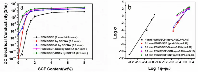
whereσis the electrical conductivity of composites,σ0is a constant that is typically assigned to the plateau conductivity of fully loaded composites,ϕis the filler weight content,ϕcis the weight ratio of the filler at the percolation threshold, and the value of critical exponent (n) depends on the system dimension and is used to interpret the mechanism of network formation. An insulator-conductor transition is observed at theϕc, and the electrical conductivity of the polymer composites increases with the filler content increasing whenϕ≥ϕc. As shown in Figure1a and Table1, the DC electrical conductivity of the PDMS/SCF composites with a thickness of 1.0 mm was increased with an increase of SCF contents, from the original filler free PDMS of∼10−12S/m to 49 S/m when the SCF content was increased to 8 wt %. Theϕcof PDMS/SCF composites was calculated to be 0.45 wt % andn= 7.45 according to Equation (1) [36–38], as shown in Figure1b.
Polymers 2019, 11, x FOR PEER REVIEW 5 of 14
transition is observed at the φc, and the electrical conductivity of the polymer composites increases
with the filler content increasing when 𝜑 ≥ 𝜑 . As shown in Figure 1a and Table 1, the DC electrical conductivity of the PDMS/SCF composites with a thickness of 1.0 mm was increased with an increase of SCF contents, from the original filler free PDMS of ∼10−12 S/m to 49 S/m when the SCF content was
[image:5.595.94.507.357.507.2]increased to 8 wt %. The φc of PDMS/SCF composites was calculated to be 0.45 wt % and n = 7.45 according to Equation (1) [36–38], as shown in Figure 1b.
Figure 1. (a) Effect of short carbon fiber (SCF) content and sample thickness on the DC electrical conductivity of PDMS composites; (b) percolation threshold fitting results.
Table 1. Comparison of electrical conductivity of PDMS/SCF composites as the effects of sample thickness and a second nanofiller. The thickness of PDMS/SCF composites was reduced from 1 to 0.1 mm by the SCFNA method, the second filler (graphene (G), superconductive carbon black (CCB), or carbon nanotube (CNT)) content is 1 wt %.
SCF (wt %) DC Electrical Conductivity (S/m)
1 mm 0.1 mm SCF-G (0.1 mm) SCF-CCB (0.1 mm) SCF-CNTs (0.1 mm)
0 1.71 × 10⁻¹² 1.71 × 10⁻¹² 1.38 × 10⁻⁵ 1.21 × 10⁻³ 6.51 × 10⁻⁴
0.5 1.40 × 10⁻¹¹ 5.50 × 10⁻⁵ 7.21 × 10⁻⁴ 1.31 3.02
1 1.01 × 10⁻⁴ 8.81 8.84 14.5 56.8
1.5 0.11 53.2 56.7 120 221
2 2.51 95.2 100 211 343
3 8.11 154 161 333 443
4 27.7 187 189 378 511
6 44.6 257 261 533 702
8 48.6 378 383 657 909
3.2. Compression-Induced Electrical Percolation of PDMS Composites
Similar to the concentration-induced percolation, a compression-induced percolation transition was observed during the SCFNA compression process, when the sample thickness or volumetric strain reached a critical value εc or under a critical pressure Pc[39], as expressed in Equations (2) and (3):
𝜑 =
𝜑
1 − ∆𝑃
(2)𝜀 = 1 − (
𝜑
𝜑
)
(3)where ∆𝑃 is the pressure increment (P- Pc) to drive the percolation transition from 𝜑 to 𝜑 . The percolation transition happened when the conducting fillers were approaching each other until a critical partial volume of the fillers was reached. As shown in Figure 1, when the thickness of the PDMS/SCF composites was reduced from 1.0 to 0.1 mm by the SCFNA compression, the overall conductivity of composites was increased significantly and the φc was reduced to 0.3 wt %. Above
[image:5.595.81.516.607.738.2]the percolation threshold, the increase of the short carbon fiber concentration from 6 to 8 wt % led to Figure 1. (a) Effect of short carbon fiber (SCF) content and sample thickness on the DC electrical
conductivity of PDMS composites; (b) percolation threshold fitting results.
Table 1. Comparison of electrical conductivity of PDMS/SCF composites as the effects of sample thickness and a second nanofiller. The thickness of PDMS/SCF composites was reduced from 1 to 0.1 mm by the SCFNA method, the second filler (graphene (G), superconductive carbon black (CCB), or carbon nanotube (CNT)) content is 1 wt %.
SCF (wt %) DC Electrical Conductivity (S/m)
1 mm 0.1 mm SCF-G (0.1 mm) SCF-CCB (0.1 mm) SCF-CNTs (0.1 mm)
0 1.71×10⁻¹² 1.71×10⁻¹² 1.38×10⁻⁵ 1.21×10⁻³ 6.51×10⁻⁴
0.5 1.40×10⁻¹¹ 5.50×10⁻⁵ 7.21×10⁻⁴ 1.31 3.02
1 1.01×10⁻⁴ 8.81 8.84 14.5 56.8
1.5 0.11 53.2 56.7 120 221
2 2.51 95.2 100 211 343
3 8.11 154 161 333 443
4 27.7 187 189 378 511
6 44.6 257 261 533 702
3.2. Compression-Induced Electrical Percolation of PDMS Composites
Similar to the concentration-induced percolation, a compression-induced percolation transition was observed during the SCFNA compression process, when the sample thickness or volumetric strain reached a critical valueεcor under a critical pressurePc[39], as expressed in Equations (2) and (3):
ϕc=
ϕ0
1−∆Pc (2)
εc=1−(
ϕ0
ϕc
) (3)
where∆Pcis the pressure increment (P−Pc) to drive the percolation transition fromϕ0toϕc. The percolation transition happened when the conducting fillers were approaching each other until a critical partial volume of the fillers was reached. As shown in Figure1, when the thickness of the PDMS/SCF composites was reduced from 1.0 to 0.1 mm by the SCFNA compression, the overall conductivity of composites was increased significantly and theϕcwas reduced to 0.3 wt %. Above the percolation threshold, the increase of the short carbon fiber concentration from 6 to 8 wt % led to a small increase of the ultimate conductivity of the PDMS/SCF composite (1 mm) from 44.6 to 48.6 S/m, only increasing by 8.97%. However, for the PDMS/SCF composite samples (0.1 mm) prepared by the SCFNA method, the conductivity was increased by 47.1%, from 257 to 378 S/m. This illustrates that when a conducting network is formed in the polymer matrix (above the concentration induced percolation threshold), a further increase in filler concentration has little contribution to the ultimate electrical conductivity. In contrast, compression may densify the conducting network, and further enhance the electrical conductivity without increasing filler concentrations. This is particularly promising in the case that the ultimate electrical conductivity of polymer composites above the concentration-induced percolation threshold can be further enhanced by a compression-induced percolation transition.
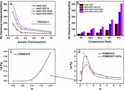
Figure2a shows the effects of sample thickness on the electrical conductivity of the PDMS/SCF composites at above its percolation threshold. As the sample thickness was reduced, the electrical conductivity of the PDMS/SCF composites was slowly increased and exhibited an abrupt enhancement when the thickness was belowdm= 0.3 mm, which indicates that a new compression-induced percolation transition occurs, i.e., a compact assembly of filler network at a higher compression ratio. A further reduction of the sample thickness to 0.1 mm led to a significant increase of the conductivity, from the original 28 S/m (at 1 mm) up to 187 S/cm for PDMS/SCF (4 wt %). Similarly, the PDMS/SCF (4 wt %)-CNT (1 wt %) composite had the electrical conductivity increased from 65 to 511 S/m. As shown in Figure1b, for the compressed composites with 0.1 mm in thickness, the addition of 1 wt % of a second nano-scale filler such as CNT or CCB reduced theϕcfrom 0.3 to 0.15 wt %, demonstrating a synergistic effect between the micro-scale short carbon fibers and the second nano-scale filler.
The effects of a second nano-scale filler along with the compression ratio (R) on the electrical conductivity of the composites are compared in Figure2b. The compression ratio R is defined as 1.0 mm over the assembly thickness of composites prepared by SCFNA, i.e., when the thickness of the composite samples was reduced to 1, 0.4, 0.3, 0.2, and 0.1 mm, the compression ratio R was 1, 2.5, 3.3, 5, and 10, respectively.
Polymers2019,11, 56 7 of 14
Polymers 2019, 11, x FOR PEER REVIEW 6 of 14
a small increase of the ultimate conductivity of the PDMS/SCF composite (1 mm) from 44.6 to 48.6 S/m, only increasing by 8.97%. However, for the PDMS/SCF composite samples (0.1 mm) prepared by the SCFNA method, the conductivity was increased by 47.1%, from 257 to 378 S/m. This illustrates that when a conducting network is formed in the polymer matrix (above the concentration induced percolation threshold), a further increase in filler concentration has little contribution to the ultimate electrical conductivity. In contrast, compression may densify the conducting network, and further enhance the electrical conductivity without increasing filler concentrations. This is particularly promising in the case that the ultimate electrical conductivity of polymer composites above the concentration-induced percolation threshold can be further enhanced by a compression-induced percolation transition.
Figure 2a shows the effects of sample thickness on the electrical conductivity of the PDMS/SCF composites at above its percolation threshold. As the sample thickness was reduced, the electrical conductivity of the PDMS/SCF composites was slowly increased and exhibited an abrupt enhancement when the thickness was below dm = 0.3 mm, which indicates that a new compression-induced percolation transition occurs, i.e., a compact assembly of filler network at a higher compression ratio. A further reduction of the sample thickness to 0.1 mm led to a significant increase of the conductivity, from the original 28 S/m (at 1 mm) up to 187 S/cm for PDMS/SCF (4 wt %). Similarly, the PDMS/SCF (4 wt %)-CNT (1 wt %) composite had the electrical conductivity increased from 65 to 511 S/m. As shown in Figure 1b, for the compressed composites with 0.1 mm in thickness, the addition of 1 wt % of a second nano-scale filler such as CNT or CCB reduced the φc from 0.3 to
[image:7.595.97.501.91.383.2]0.15 wt %, demonstrating a synergistic effect between the micro-scale short carbon fibers and the second nano-scale filler.
Figure 2. (a) Effect of sample thickness on the DC electrical conductivity of PDMS composites prepared by the SCFNA method; (b) effect of compression ratio (R) on the DC electrical conductivity of PDMS composites by the SCFNA method; (c,d) the strain sensitivity Ks of the conductivity of the PDMS composites during the SCFNA compression process.
The effects of a second nano-scale filler along with the compression ratio (R) on the electrical conductivity of the composites are compared in Figure 2b. The compression ratio R is defined as 1.0 mm over the assembly thickness of composites prepared by SCFNA, i.e., when the thickness of the
Figure 2.(a) Effect of sample thickness on the DC electrical conductivity of PDMS composites prepared by the SCFNA method; (b) effect of compression ratio (R) on the DC electrical conductivity of PDMS composites by the SCFNA method; (c,d) the strain sensitivity Ks of the conductivity of the PDMS composites during the SCFNA compression process.
To demonstrate the dependence of electrical conductivity on partial volume of the fillers (sample thickness), the strain-sensitivity coefficientKsis plotted against the filler concentration according to Equation (4), and is shown in Figure2c,d.
KS =
dσ σ /
dV
V (4)
wheredV/Vis the volumetric strain, causing a relative increment of the conductivity (dσ σ).
As shown in Figure2c, the electrical conductivity orKsis not sensitive to the sample thickness when the SCF content is lower than 0.15 wt %. As the SCF content increases, 0.25 wt % <ϕ<0.5 wt %, thelg Ksincreases abruptly and reaches a maximum peak at 0.5 wt %, close to its percolation transition as determined in Figure1b, indicating the formation of a compression-induced conducting network. Thelg Ksgradually decreases as the filler concentration increases, indicating that once a compact conducting network has formed, the conductivity becomes less sensitive to the sample thickness and filler concentration.
In the case of PDMS/SCF-CNTs, the addition of 1 wt % of CNTs facilitates the formation of a conducting SCF network at lower concentrations due to the gap-filling effect. In the SCF concentration range of 0.15 wt % <ϕ< 1 wt %, thelg Ksincreases abruptly and then drops as the SCF concentration increases. Thelg Kspeak value is lower than that of the PDMS/SCF composite, which is because the addition of CNTs makes the network more compact, and thus reduces the strain sensitivity.
conductivity of PDMS composites can be more effectively enhanced by constructing a compact conducting network instead of increasing the filler loading. By further increasing the packing density by adding a second nanofiller or increasing the filler concentration, the electrical conductivity can be significantly further enhanced.
3.3. Characterization of the Conducting Filler Network in PDMS
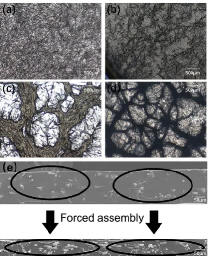
Reducing the gap between adjacent filler particles would benefit electron conduction [8,40,41], since the electrons can transport between adjacent conducting fillers within an average distance less than 100 nm, according to conductive passage theory [42]. Figure 3shows the morphology evolution of the short carbon fiber network during the preparation of the PDMS/SCF (4 wt %) composites. A homogeneously-dispersed short carbon fiber network was formed in the PDMS matrix after melt-compounding, as shown in Figure3a. When further subjected to the strong shearing force in the conical twin-screw extrusion process, the short carbon fiber filler agglomerated and self-assembled, as shown in Figure3b. After the first stage of compression, the self-assembly network was formed, as shown in Figure3c, and was subsequently condensed by the second stage of spatial confining compression (SCFNA) to create a forced assembly network in Figure3d. From the cross-sectional images in Figure3e, the short carbon fiber framework was compacted by the forced assembly and the average distance between the short carbon fibers was reduced from more than 15µm to less than 100 nm, which creates the electron conduction pathways through both field emission and conductive passage. Figure4shows the SEM images of the cross-section of PDMS/SCF-CNT samples. It is observed that CNTs and SCF are homogeneously dispersed in PDMS before compression, and most CNTs are dispersed in PDMS rather than around SCF, as shown in Figure4a. After self-assembly, most CNTs aggregated to form a conductive network and moved towards SCF as shown in Figure4b. Figures4c and5b show that most CNTs were dispersed around SCF, filling the gap between the SCF network after forced compression. The more compact SCF network and CNT network help enhance the conductivity of PDMS/SCF-CNT composites as a result of a synergistic effect.
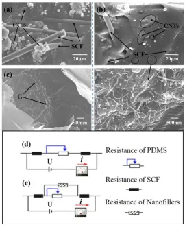
The gap-filling effect of an additional nano-scale filler on the conducting network of short carbon fibers is illustrated by SEM imaging in Figure5. In the PDMS/SCF-CCB composites, the majority of the CCB particles are located inside the network of short carbon fibers which fill the space between short carbon fibers, as shown in Figure5a. A synergistic effect of a combination of CCB and short carbon fibers could enhance the continuity of conductive pathways in the compact carbon fiber conductive forced assembled network. As shown in Figure5b, most CNTs are dispersed regularly around the short carbon fiber framework. The average spacing of adjacent CNTs in the network is less than 100 nm, and the interconnection between the long CNTs with the compact short carbon fiber network accounts for the enhanced conductivity of PDMS/SCF-CNT composites. In comparison, the few-layer graphene sheets are mostly dispersed in the PDMS matrix rather than inside of the carbon fiber network, as shown in Figure5c, implying a lower synergy efficiency of the combination of graphene and SCF in PDMS composites. In addition, the agglomerates of graphene sheets may also account for the low conductivity and poor contribution for the PDMS/SCF composites.
Ohm’s Law can be used to explain why the reduced separation between filler particles of the conductive network could effectively improve the electrical conductivity of composites. As seen in Figure5d, when the adjacent short carbon fibers are closer, the effective resistance of the PDMS region between the short carbon fibers decreases, as a result, the electrical conductivity of the PDMS/SCF composites is increased. Moreover, with the addition of a second nano-scale filler, a gap-filling conductive network is formed among the SCFs, as shown in Figure5e of the conductive model for PDMS/SCF-CNT and PDMS/SCF-CCB composites. This indicates that the PDMS resistance between adjacent SCFs is parallel with a small resistance, which greatly improves the conductivity of the composites.
Polymers2019,11, 56 9 of 14
of shorter carbon fiber network in PDMS. The SCF was homogeneously dispersed in PDMS by melt-compounding, as shown in Figure3a, due to the strong shearing and stretching stress in the conical twin-screw extrusion process. During the two-step compression, when the thickness of the sample was larger thandm, the SCF could assemble to form a conducting network which could wiggle in the liquid PDMS by free compression. This caused the self-assembled SCF network to become more compact, as shown in Figure3c. At the following forced assembly process, namely, forced compression, the sample thickness was further reduced to belowdm; a noteworthy densification of the network threads was therefore formed. Due to the restriction of wiggling freedom of the network, the SCF at the threads would tend to get closer which squeezed the extra polymer out of the filler granules in a special confining compression process, as shown in Figure3d. The compression force could be transmitted to the granules to break the balance of the self-assembly network, and the self-assembled network was forced to pack more densely, which resulted in enhanced electrical conductivity [33].
Polymers 2019, 11, x FOR PEER REVIEW 8 of 14
[image:9.595.190.405.263.527.2]images in Figure 3e, the short carbon fiber framework was compacted by the forced assembly and the average distance between the short carbon fibers was reduced from more than 15 μm to less than 100 nm, which creates the electron conduction pathways through both field emission and conductive passage. Figure 4 shows the SEM images of the cross-section of PDMS/SCF-CNT samples. It is observed that CNTs and SCF are homogeneously dispersed in PDMS before compression, and most CNTs are dispersed in PDMS rather than around SCF, as shown in Figure 4a. After self-assembly, most CNTs aggregated to form a conductive network and moved towards SCF as shown in Figure 4b. Figures 4c and 5b show that most CNTs were dispersed around SCF, filling the gap between the SCF network after forced compression. The more compact SCF network and CNT network help enhance the conductivity of PDMS/SCF-CNT composites as a result of a synergistic effect.
[image:9.595.128.471.614.696.2]Figure 3. Morphology evolution of short carbon fiber network in PDMS: (a) homogeneous dispersion of short carbon fibers in PDMS after melt mixing; (b) a self-assembly network formed during conical twin-screw extrusion; (c) the free assembly network under compression; (d) forced assembly network under spatial confining compression; and (e) cross-section morphologies showing the evolution of the short carbon fiber network from self-assembly to forced assembly.
Figure 4. Morphology evolution of PDMS/SCF (8 wt %)-CNT (1 wt %) composites: (a) homogeneous dispersion of CNT and SCF in PDMS before compression; (b) the free assembly network under compression; (c) forced assembly network under spatial confining compression.
Figure 3.Morphology evolution of short carbon fiber network in PDMS: (a) homogeneous dispersion of short carbon fibers in PDMS after melt mixing; (b) a self-assembly network formed during conical twin-screw extrusion; (c) the free assembly network under compression; (d) forced assembly network under spatial confining compression; and (e) cross-section morphologies showing the evolution of the short carbon fiber network from self-assembly to forced assembly.
Polymers 2019, 11, x FOR PEER REVIEW 8 of 14
images in Figure 3e, the short carbon fiber framework was compacted by the forced assembly and the average distance between the short carbon fibers was reduced from more than 15 μm to less than 100 nm, which creates the electron conduction pathways through both field emission and conductive passage. Figure 4 shows the SEM images of the cross-section of PDMS/SCF-CNT samples. It is observed that CNTs and SCF are homogeneously dispersed in PDMS before compression, and most CNTs are dispersed in PDMS rather than around SCF, as shown in Figure 4a. After self-assembly, most CNTs aggregated to form a conductive network and moved towards SCF as shown in Figure 4b. Figures 4c and 5b show that most CNTs were dispersed around SCF, filling the gap between the SCF network after forced compression. The more compact SCF network and CNT network help enhance the conductivity of PDMS/SCF-CNT composites as a result of a synergistic effect.
Figure 3. Morphology evolution of short carbon fiber network in PDMS: (a) homogeneous dispersion of short carbon fibers in PDMS after melt mixing; (b) a self-assembly network formed during conical twin-screw extrusion; (c) the free assembly network under compression; (d) forced assembly network under spatial confining compression; and (e) cross-section morphologies showing the evolution of the short carbon fiber network from self-assembly to forced assembly.
Figure 4. Morphology evolution of PDMS/SCF (8 wt %)-CNT (1 wt %) composites: (a) homogeneous dispersion of CNT and SCF in PDMS before compression; (b) the free assembly network under compression; (c) forced assembly network under spatial confining compression.
Polymers 2019, 11, x FOR PEER REVIEW 9 of 14
Figure 5. SEM images of PDMS/SCF (4 wt %) composites containing 1 wt % of a second nanofiller: (a) CCB; (b) CNTs; and (c) graphene; resistance of conductive network in the polymer matrix (d) PDMS/SCF and (e) PDMS/SCF containing a second filler.
The gap-filling effect of an additional nano-scale filler on the conducting network of short carbon fibers is illustrated by SEM imaging in Figure 5. In the PDMS/SCF-CCB composites, the majority of the CCB particles are located inside the network of short carbon fibers which fill the space between short carbon fibers, as shown in Figure 5a. A synergistic effect of a combination of CCB and short carbon fibers could enhance the continuity of conductive pathways in the compact carbon fiber conductive forced assembled network. As shown in Figure 5b, most CNTs are dispersed regularly around the short carbon fiber framework. The average spacing of adjacent CNTs in the network is less than 100 nm, and the interconnection between the long CNTs with the compact short carbon fiber network accounts for the enhanced conductivity of PDMS/SCF-CNT composites. In comparison, the few-layer graphene sheets are mostly dispersed in the PDMS matrix rather than inside of the carbon fiber network, as shown in Figure 5c, implying a lower synergy efficiency of the combination of graphene and SCF in PDMS composites. In addition, the agglomerates of graphene sheets may also account for the low conductivity and poor contribution for the PDMS/SCF composites.
[image:10.595.145.450.487.673.2]Ohm’s Law can be used to explain why the reduced separation between filler particles of the conductive network could effectively improve the electrical conductivity of composites. As seen in Figure 5d, when the adjacent short carbon fibers are closer, the effective resistance of the PDMS region between the short carbon fibers decreases, as a result, the electrical conductivity of the PDMS/SCF composites is increased. Moreover, with the addition of a second nano-scale filler, a gap-filling
Figure 5.SEM images of PDMS/SCF (4 wt %) composites containing 1 wt % of a second nanofiller: (a) CCB; (b) CNTs; and (c) graphene; resistance of conductive network in the polymer matrix (d) PDMS/SCF and (e) PDMS/SCF containing a second filler.
Polymers 2019, 11, x FOR PEER REVIEW 10 of 14
conductive network is formed among the SCFs, as shown in Figure 5e of the conductive model for PDMS/SCF-CNT and PDMS/SCF-CCB composites. This indicates that the PDMS resistance between adjacent SCFs is parallel with a small resistance, which greatly improves the conductivity of the composites.
Figure 6 shows the mechanism of the SCFNA process and the structure development of conducting a filler network in polymer composites. Figure 3 shows the mechanism of the morphology evolution of shorter carbon fiber network in PDMS. The SCF was homogeneously dispersed in PDMS by melt-compounding, as shown in Figure 3a, due to the strong shearing and stretching stress in the conical twin-screw extrusion process. During the two-step compression, when the thickness of the sample was larger than dm, the SCF could assemble to form a conducting network which could wiggle in the liquid PDMS by free compression. This caused the self-assembled SCF network to become more compact, as shown in Figure 3c. At the following forced assembly process, namely, forced compression, the sample thickness was further reduced to below dm; a noteworthy densification of the network threads was therefore formed. Due to the restriction of wiggling freedom of the network, the SCF at the threads would tend to get closer which squeezed the extra polymer out of the filler granules in a special confining compression process, as shown in Figure 3d. The compression force could be transmitted to the granules to break the balance of the assembly network, and the self-assembled network was forced to pack more densely, which resulted in enhanced electrical conductivity [33].
Figure 6. Mechanism of the SCFNA process initiated compact conducting filler network and highly enhanced electrical conductivity of polymer composites.
Therefore, the SCFNA process provides a simple route to construct a continuous and compact short carbon fiber micro-network in the polymeric matrix by simply applying mechanical force, which enhances the electrical conductivity up to 378 S/m, 7.8 times higher than that of the PDMS/SCF composites by compounding. Moreover, the gap-filling effect of a second nano-scale filler such as CNTs has interconnected the micro-SCF network. As a result, the electrical conductivity of the PDMS composites containing hybrid fillers and processed via SCFNA can be further enhanced to as high as 909 S/m.
3.4. Mechanical Properties
The mechanical properties of PDMS composites with SCF (0–8 wt %), and 1 wt % of a nano-sized filler (CNT, CCB, and G) are shown in Table 2—the sample thickness is 0.2 mm. The maximum tensile strength of PDMS/SCF composites decreased from 4.5 ± 0.1 MPa to 2.4 ± 0.1 MPa when the SCF content increased from 0 to 8 wt %. The reduced properties can be ascribed to the higher contents of micro-SCF and the poor interfacial interaction between SCF and PDMS. After addition of 1 wt % nanofillers into PDMS/SCF (4 wt %) composites, the tensile strength and elongation at break of the
Figure 6.Mechanism of the SCFNA process initiated compact conducting filler network and highly enhanced electrical conductivity of polymer composites.
Polymers2019,11, 56 11 of 14
the micro-SCF network. As a result, the electrical conductivity of the PDMS composites containing hybrid fillers and processed via SCFNA can be further enhanced to as high as 909 S/m.
3.4. Mechanical Properties
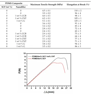
[image:11.595.122.475.386.751.2]The mechanical properties of PDMS composites with SCF (0–8 wt %), and 1 wt % of a nano-sized filler (CNT, CCB, and G) are shown in Table2—the sample thickness is 0.2 mm. The maximum tensile strength of PDMS/SCF composites decreased from 4.5±0.1 MPa to 2.4±0.1 MPa when the SCF content increased from 0 to 8 wt %. The reduced properties can be ascribed to the higher contents of micro-SCF and the poor interfacial interaction between SCF and PDMS. After addition of 1 wt % nanofillers into PDMS/SCF (4 wt %) composites, the tensile strength and elongation at break of the composites were enhanced. Graphene showed a better mechanical reinforcement effect than CNT and CCB. With the addition of 1 wt % graphene, the maximum tensile strength of PDMS/SCF composites improved from 2.8±0.1 MPa to 3.8±0.2 MPa. The two-dimensional graphene nanosheets offer a stronger interface layer with PDMS as compared to one-dimensional CNT or granular CCB, and the graphene is mainly located in the PDMS rich regions of the composites, which would be effective in reinforcement of PDMS. Meanwhile, graphene presents a folded morphological distribution in PDMS as shown in Figure5c, which would benefit the enhancement of the tensile strength and elongation at break. Nevertheless, both the CNT and CCB improved the tensile strength of PDMS/SCF composites, because the nanosized CNT and CCB interact with the PDMS matrix stronger than the microsized SCF. Figure7shows the tensile curve of PDMS/SCF (8 wt %) and PDMS/SCF (8 wt %)-CNT (1 wt %) samples.
Table 2.Mechanical properties of PDMS composites at thickness 0.2 mm.
PDMS Composite
Maximum Tensile Strength (MPa) Elongation at Break (%) SCF (wt %) Nanofiller
0 0 4.5±0.1 110±2
1 0 3.9±0.2 96±4
0 1 wt % CCB 4.0±0.1 98±1
0 1 wt % CNT 4.2±0.1 105±1
0 1 wt % G 5.1±0.1 125±1
2 0 3.6±0.2 91±4
3 0 3.2±0.2 83±4
4 0 2.8±0.2 72±4
8 0 2.4±0.1 60±3
4 1 wt % CCB 2.9±0.2 73±3
8 1 wt % CCB 2.7±0.2 64±4
4 1 wt % CNT 3.1±0.2 77±3
8 1 wt % CNT 2.9±0.2 71±3
4 1 wt % G 3.8±0.2 94±3
8 1 wt % G 3.5±0.2 84±3
Polymers 2019, 11, x FOR PEER REVIEW 11 of 14
composites were enhanced. Graphene showed a better mechanical reinforcement effect than CNT
and CCB. With the addition of 1 wt % graphene, the maximum tensile strength of PDMS/SCF
composites improved from 2.8 ± 0.1 MPa to 3.8 ± 0.2 MPa. The two-dimensional graphene nanosheets
offer a stronger interface layer with PDMS as compared to one-dimensional CNT or granular CCB,
and the graphene is mainly located in the PDMS rich regions of the composites, which would be
effective in reinforcement of PDMS. Meanwhile, graphene presents a folded morphological
distribution in PDMS as shown in Figure 5c, which would benefit the enhancement of the tensile
strength and elongation at break. Nevertheless, both the CNT and CCB improved the tensile strength
of PDMS/SCF composites, because the nanosized CNT and CCB interact with the PDMS matrix
stronger than the microsized SCF. Figure 7 shows the tensile curve of PDMS/SCF (8 wt %) and
PDMS/SCF (8 wt %)-CNT (1 wt %) samples.
Table 2. Mechanical properties of PDMS composites at thickness 0.2 mm.
PDMS Composite
Maximum Tensile Strength (MPa) Elongation at Break (%)
SCF (wt %)
Nanofiller
0
0
4.5 ± 0.1
110 ± 2
1
0
3.9 ± 0.2
96 ± 4
0
1 wt % CCB
4.0 ± 0.1
98 ± 1
0
1 wt % CNT
4.2 ± 0.1
105 ± 1
0
1 wt % G
5.1 ± 0.1
125 ± 1
2
0
3.6 ± 0.2
91 ± 4
3
0
3.2 ± 0.2
83 ± 4
4
0
2.8 ± 0.2
72 ± 4
8
0
2.4 ± 0.1
60 ± 3
4
1 wt % CCB
2.9 ± 0.2
73 ± 3
8
1 wt % CCB
2.7 ± 0.2
64 ± 4
4
1 wt % CNT
3.1 ± 0.2
77 ± 3
8
1 wt % CNT
2.9 ± 0.2
71 ± 3
4
1 wt % G
3.8 ± 0.2
94 ± 3
8
1 wt % G
3.5 ± 0.2
84 ± 3
Figure 7. The tensile curve of PDMS/SCF (8 wt %) and PDMS/SCF (8 wt %)-CNT (1 wt %) samples.
4. Conclusions
The incorporation of conducting fillers into an insulating polymer matrix can generally enhance
the electrical conductivity to a limited extent when beyond the percolation threshold. In this work, a
spatially confined forced network combined with a hybrid micro-nanoscale filler approach were
investigated in order to prompt highly electrical conductive polymer composites. With our
newly-designed spatially confined forced network (SCFNA) process, the electrical conductivity of
PDMS/short carbon fiber (SCF) composites was increased by 7.8 times in comparison to the
4. Conclusions
The incorporation of conducting fillers into an insulating polymer matrix can generally enhance the electrical conductivity to a limited extent when beyond the percolation threshold. In this work, a spatially confined forced network combined with a hybrid micro-nanoscale filler approach were investigated in order to prompt highly electrical conductive polymer composites. With our newly-designed spatially confined forced network (SCFNA) process, the electrical conductivity of PDMS/short carbon fiber (SCF) composites was increased by 7.8 times in comparison to the traditional compounding method. The addition of a nano-scale filler, such as CCB or CNT, further increased the conductivity over 2 times higher at above the percolation threshold of SCF; this was a result of a synergy effect of the hierarchical filler network. The spatially confined forced network provides a simple route to construct a continuous and compact conducting filler network in PDMS/SCF composites and results in super high electrical conductivity yet mechanical flexible composites with lower filler concentrations. This approach will significantly prompt the applications of conductive polymer composites in the areas of flexible sensors and intelligent wearable products.
Author Contributions:For research articles with several authors, a short paragraph specifying their individual contributions must be provided. The following statements should be used “conceptualization, X.G., C.W. and M.D.; methodology, X.G.; software, X.G. and Y.H.; validation, X.G. and D.W.; formal analysis, X.G. and Y.L.; investigation, X.G. and X.H.; resources, D.W.; data curation, X.G., H.X. and X.F.; writing—original draft preparation, X.G.; writing—review and editing, X.G. and C.W.; visualization, C.W.; supervision, X.X.; project administration, D.W.; funding acquisition, Y.H., X.G. and D.W.”, please turn to the CRediT taxonomy for the term explanation. Authorship must be limited to those who have contributed substantially to the work reported.
Funding:This work was supported by the National Nature Science Foundation of China (Grant No.51673020) and by the Fundamental Research Funds for the Central Universities (Grant No.ZY1812, JD1810).
Conflicts of Interest:The authors declare no conflict of interest.
References
1. Lu, Q.; Wang, X.; Cao, J.; Chen, C.; Chen, K.; Zhao, Z.; Niu, Z.; Chen, J. Freestanding carbon fiber cloth/sulfur composites for flexible room-temperature sodium-sulfur batteries. Energy Storage Mater. 2017,8, 77–84. [CrossRef]
2. Han, J.H.; Zhang, H.; Chen, M.J.; Wang, D.; Liu, Q.; Wu, Q.L.; Zhang, Z. The combination of carbon nanotube buckypaper and insulating adhesive for lightning strike protection of the carbon fiber/epoxy laminates. Carbon2015,94, 101–113. [CrossRef]
3. Zeng, Z.; Jin, H.; Chen, M.J.; Li, W.W.; Zhou, L.C.; Zhang, Z. Lightweight and hierarchically porous MWCNT/WPU composites for ultra-high performance electromagnetic interference shielding. Adv. Funct. Mater.2016,26, 303–310. [CrossRef]
4. Kuang, J.; Dai, Z.H.; Liu, L.Q.; Yang, Z.; Jin, M.; Zhang, Z. Synergistic effects from graphene and carbon nanotubes enable ordered hierarchical structure foams with combination of compressibility, super-elasticity and stability, and their potential application as pressure sensors.Nanoscale2015,7, 9252–9260. [CrossRef] [PubMed]
5. Liu, Q.; Liu, L.Q.; Kuang, J.; Dai, Z.; Gao, Y.; Han, J.; Zhang, Z. Carbon nanomaterials based electrothermal air-pump actuators.Nanoscale2014,6, 6932–6938. [CrossRef] [PubMed]
6. Gu, H.; Guo, J.; Wei, H.; Guo, S.; Liu, J.; Huang, Y.; Khan, M.A.; Wang, X.; Young, D.P.; Wei, S.; et al. Strengthened Magnetoresistive Epoxy Nanocomposite Papers Derived from Synergistic Nanomagnetite-Carbon Nanofiber Nanohybrids.Adv. Mater.2015,27, 6277–6282. [CrossRef] [PubMed] 7. Deng, H.; Lin, L.; Ji, M.; Zhang, S.; Yang, M.; Fu, Q. Progress on the morphological control of conductive network
in conductive polymer composites and the use as electroactive multifunctional materials. Prog. Polym. Sci.
2014,39, 627–655. [CrossRef]
Polymers2019,11, 56 13 of 14
9. Ma, Y.; Wu, D.; Liu, Y.; Li, X.; Qiao, H.; Yu, Z.Z. Electrically conductive and super-tough polypropylene/carbon nanotube nanocomposites prepared by melt compounding.Compos. Part B2014,56, 384–391. [CrossRef]
10. Zhang, C.; Zhu, J.; Ouyang, M.; Ma, C.A. Electric field controlled formation and dissociation of multiwalled carbon nanotube conductive pathways in a polymer melt.Appl. Phys. Lett.2009,94, 111915. [CrossRef] 11. Zhang, K.; Yu, H.-O.; Shi, Y.-D.; Chen, Y.-F.; Zeng, J.-B.; Guo, J.; Wang, B.; Guo, Z.; Wang, M.
Morphological regulation improved electrical conductivity and electromagnetic interference shielding in poly (L-lactide)/poly (ε-caprolactone)/carbon nanotube nanocomposites via constructing stereocomplex crystallites.J. Mater. Chem. C2017,5, 2807–2817. [CrossRef]
12. Xiang, M.; Li, C.; Ye, L. Structure and conformation of polyetheramine in confined space of graphene oxide and its enhancement on the electrically conductive properties of monomer casting nylon-6.Compos. Part A
2017,95, 1–11. [CrossRef]
13. Yoo, T.J.; Hwang, E.B.; Jeong, Y.G. Thermal and electrical properties of poly(phenylene sulfide)/carbon nanotube nanocomposite films with a segregated structure.Compos. Part A2016,91, 77–84. [CrossRef] 14. Chiu, F.C.; Chen, Y.J. Evaluation of thermal, mechanical, and electrical properties of PVDF/GNP binary and
PVDF/PMMA/GNP ternary nanocomposites.Compos. Part A2015,68, 62–71. [CrossRef]
15. Zhang, C.; Wang, L.; Wang, J.; Ma, C.A. Self-assembly and conductive net-work formation of vapor-grown carbon fiber in a poly(vinylidenefluoride) melt.Carbon2008,46, 2053–2058. [CrossRef]
16. Lan, Y.; Liu, H.; Cao, X.; Zhao, S.; Dai, K.; Yan, X.; Zheng, G.; Liu, C.; Shen, C.; Guo, Z. Electrically conductive thermoplastic polyurethane/polypropylene nanocomposites with selectively distributed graphene.Polymer
2016,97, 11–19. [CrossRef]
17. Zhu, J.; Wei, S.; Ryu, J.; Budhathoki, M.; Liang, G.; Guo, Z. In situ stabilized carbon nanofiber (CNF) reinforced epoxy nanocomposites.J. Mater. Chem.2010,20, 4937–4948. [CrossRef]
18. Zhang, H.; Xu, X. Improving the transesterification and electrical conductivity of vitrimers by doping with conductive polymer wrapped carbon nanotubes.Compos. Part A2017,99, 15–22. [CrossRef]
19. Jo, Y.; Kim, J.Y.; Kim, S.-Y.; Seo, Y.-H.; Jang, K.-S.; Lee, S.Y.; Jung, S.; Ryu, B.-H.; Kim, H.S.; Park, J.-U.; et al. 3D-printable, highly conductive hybrid composites employing chemically-reinforced, complex dimensional fillers and thermoplastic triblock copolymers.Nanoscale2017,9, 5072–5084. [CrossRef]
20. Zhang, L.; Wan, C.; Zhang, Y. Morphology and electrical properties of polyamide
6/polypropylene/multi-walled carbon nanotubes composites.Compos. Sci. Technol.2009,69, 2212–2217. [CrossRef]
21. Liu, H.; Gao, J.; Huang, W.; Dai, K.; Zheng, G.; Liu, C.; Shen, C.; Yan, X.; Guo, J.; Guo, Z. Electrically conductive strain sensing polyurethane nanocomposites with synergistic carbon nanotubes and graphene bifillers.Nanoscale2016,8, 12977–12989. [CrossRef] [PubMed]
22. Sethi, D.; Ram, R.; Khastgir, D. Electrical conductivity and dynamic mechanical properties of silicon rubber-based conducting composites: Effect of cyclic deformation, pressure and temperature.Polym. Int.
2017,66, 1295–1305. [CrossRef]
23. Wu, S.; Zhang, J.; Ladani, R.B.; Ravindran, A.R.; Mouritz, A.P.; Kinloch, A.J.; Wang, C.H. Novel Electrically Conductive Porous PDMS/Carbon Nanofiber Composites for Deformable Strain Sensors and Conductors. ACS Appl. Mater. Interfaces2017,9, 14207–14215. [CrossRef]
24. Fisher, S.C.L.; Levy, O.; Kroner, E.; Hensel, R.; Karp, J.M.; Arzt, E. Bioinspired polydimethylsiloxane-based composites with high shear resistance against wet tissue. J. Mech. Behav. Biomed. Mater. 2016,61, 87–95. [CrossRef] [PubMed]
25. Christopher, J.B. Recent advances in materials and flexible electronics for peripheral nerve interfaces. Bioelectron. Med.2018,4, 6.
26. Joshi, N.; Saxena, V.; Singh, A.; Koiry, S.P.; Debnath, A.K.; Chehimi, M.M.; Aswal, D.K.; Guptaa, S.K. Flexible H2S sensor based on gold modified polycarbazole films. Sensors Actuators B Chem. 2014,200, 227–234. [CrossRef]
28. Kim, J.H.; Hwang, J.-Y.; Hwang, H.R.; Kim, H.S.; Lee, J.H.; Seo, J.; Shin, U.S.; Lee, S.-H. Simple and cost-effective method of highly conductive and elastic carbon nanotube/polydimethylsiloxane composite for wearable electronics.Sci. Rep.2018,8, 1375. [CrossRef]
29. Park, O.K.; Lee, W.; Hwang, J.Y.; You, N.-H.; Jeong, Y.; Kim, S.M.; Ku, N.-C. Mechanical and electrical properties of thermochemically cross-linked polymer carbon nanotube fibers. Compos. Part A2016, 91, 222–228. [CrossRef]
30. Kong, K.T.S.; Mariatti, M.; Rashid, A.A.; Busfield, J.J.C. Enhanced conductivity behavior of polydimethylsiloxane (PDMS) hybrid composites containing exfoliated graphite nanoplatelets and carbon nanotubes.Compos. Part B2014,58, 457–462. [CrossRef]
31. Zhang, S.; Deng, H.; Zhang, Q.; Fu, Q. Formation of conductive networks with both segregated and double-percolated characteristic in conductive polymer composites with balanced properties. ACS Appl. Mater. Interfaces2014,6, 6835–6844. [CrossRef] [PubMed]
32. Thongruang, W.; Spontak, R.J.; Balik, C.M. Bridged double percolation in conductive polymer composites: An electrical conductivity, morphology and mechanical property study.Polymer2002,43, 3717–3725. [CrossRef] 33. Wu, D.; Gao, X.; Sun, J.; Wu, D.; Liu, Y.; Kormakov, S.; Zheng, X.; Wu, L.; Huang, Y.; Guo, Z. Spatial Confining Forced Network Assembly for preparation of high-performance conductive polymeric composites. Compos. Part A2017,102, 88–95. [CrossRef]
34. He, X.X.; Huang, Y.; Liu, Y.; Zheng, X.T.; Kormakov, S.; Sun, J.Y.; Zhuang, J.; Gao, X.L.; Wu, D.M. Improved thermal conductivity of polydimethylsiloxane/short carbon fibre composites prepared by spatial confining forced network assembly.J. Mater. Sci.2018. [CrossRef]
35. Essam, J.W. Percolation theory.Rep. Prog. Phys.1980,43, 833. [CrossRef]
36. Shtein, M.; Nadiv, R.; Buzaglo, M.; Kahil, K.; Regev, O. Thermally Conductive Graphene-Polymer Composites: Size, Percolation, and Synergy Effects.Chem. Mater.2015,27, 2100–2106. [CrossRef]
37. Badard, M.; Combessis, A.; Allais, A.; Flandin, L. Modeling the dynamic percolation of carbon nanotubes and revisiting critical exponents.Mater. Chem. Phys.2017,191, 89–95. [CrossRef]
38. Saberi, A.A. Recent advances in percolation theory and its applications.Phys. Rep.2015,578, 1–32. [CrossRef] 39. Chelidze, T.; Gueguen, Y. Pressure-induced percolation transitions in composites.J. Phys. D Appl. Phys.1998,
31, 2877–2885. [CrossRef]
40. Chen, Y.; Pan, F.; Wang, S.; Liu, B.; Zhang, J. Theoretical estimation on the percolation threshold for polymer matrix composites with hybrid fillers.Compos. Struct.2015,124, 292–299. [CrossRef]
41. Rahatekar, S.S.; Shaffer, M.S.P.; Elliott, J.A. Modelling percolation in fibre and sphere mixtures: Routes to more efficient network formation.Compos. Sci. Technol.2010,70, 356–362. [CrossRef]
42. Rajagopal, C.; Satyam, M. Studies on electrical conductivity of insulator-conductor composites.J. Appl. Phys.
1978,49, 5536–5542. [CrossRef]