Microkernel Development for Embedded Systems
Rodrigo Maximiano Antunes de Almeida, Luis Henrique de Carvalho Ferreira, Carlos Henrique Valério
IESTI-Systems Engineering and Information Technology Institute, UNIFEI-Federal University of Itajubá, Itajubá, Brazil. Email: [email protected], [email protected], [email protected]
Received October 27th, 2012; revised November 25th, 2012; accepted December 3rd, 2012
ABSTRACT
This paper presents the development of a microkernel with a device driver controller for embedded systems. The im- plementation was done in C language aiming low cost microcontrollers. The proposed system allowed to perform soft real-time activities while keeping the drivers and the application isolated by a secure layer. The callback system proved itself extremely simple to use while still maintaining the security of the system regarding the temporal constraints.
Keywords: Embedded Systems; Microkernel; Device Driver Controller; Hardware Devices; Callback
1. Introduction
The embedded system development is a complex area in which the developer needs to have a deep understanding of the underlying hardware with its configurations and registers. One of the solutions to reduce this complexity is to use an operating system. This introduces in the sys- tem a programming layer that operates as a translator, passing the messages from processes to the hardware devices, making the system development easier [1].
This paper presents a microkernel aimed at low re-sources embedded systems. In order to provide a more complete system a device driver controller was devel-oped to operate with the microkernel.
This paper also proposes a standard for the hardware driver with a common set of functions. The standardiza-tion of these funcstandardiza-tions allows the developer to add a new device driver or modify an existing driver without the need to change the kernel code. Also it is possible to cre-ate a new abstraction layer allowing complex hardware resources like interrupts and callbacks to be easily used by embedded systems developers.
The Section 2 presents an overview of some defini- tions and discuss timing scheduler issues.
In the Section 3 the microkernel development process is presented with the decisions taken to the system archi- tecture. It also presents the developed callback process with its requirements.
A practical example with the results obtained in this paper is presented in the Section 4 followed by the con- clusions on Section 5.
2. Embedded Systems Concepts
Embedded systems are systems designed for a single
purpose or a single application and usually have limited memory and processing resources [2].
Generally they are not designed to be programmed or modified by the end user. In some systems the user may change or configure some of the system behavior, but not the function that it performs [3].
In most cases, these systems are designed for applica- tions that do not require human intervention and typically they interact only with the environment where they are, gathering data from sensors and modifying the environ- ment with actuators [2]. In some of these systems there are real-time requirements and not completing a task in the required time can result in data/quality loss or even cause damage to the system or be hazardous to the peo-ple around it [3]. In these cases, the use of a real-time kernel can ensure that the functions execution to satisfy the predetermined times if some conditions are met [4].
2.1. Processes
A process is a piece of executable code, which can be represented by a computational function. Besides the code itself, other information may be necessary and is stored with the process.
For a soft real-time system, it is necessary to indicate the processes temporal needs. For this work it is neces-sary that each process has its own countdown timer and also inform the implementation period.
2.2. Kernel
In general, a kernel has three main responsibilities [6]: to manage and coordinate the execution of processes
in the CPU through some criteria;
to handle the available memory and coordinate the processes to access it;
to interface the communication between hardware and processes.
Figure 1 shows the kernel responsibilities, showing the relationships between it and the other system com- ponents.
The way the kernel manages processes is a critical point in development, especially in the context of em-bedded systems, where processes may have restrictions with respect to delays in its execution [7].
When there is no kernel, the entire responsibility of organizing the processes, the hardware and the applica- tions falls on the programmer, complicating even more the management of critical processes.
A monolithic kernel is the one where all resources are implemented within the same level, having all functions and procedures required to operate the system inside it- self, i.e., operations on input/output, memory management and processes are all implemented in the same module.
The microkernel differs from a monolithic kernel be- cause its goal is to be as simple as possible, leaving eve- rything that is not essential to its operation in other layers. Therefore the vast majority of drivers and routines are implemented outside the kernel, increasing both security and the system stability.
The option of a microkernel provides a greater system reliability, since each module can be separated and thus having its errors contained [8]. However this architecture can insert an unnecessary overhead in communication between the kernel and modules, and this is the most critical point in the microkernel development [9].
2.3. Time Related Conditions
[image:2.595.310.539.516.602.2]Some of the embedded system applications need to run some of their processes periodically. The failure to exe-cute or even a small delay on these processes, can lead to serious consequences for the system as a whole. Some systems can even completely fail if these deadlines are
Figure 1. Kernel, application and resources.
not met [10].
There are at least three conditions that must be satis-fied in order to implement timing conditions on the ker-nel [11]:
The system must have a hardware interrupt which occurs at a precise rate and is capable of running an arbitrary code;
The kernel must be informed of the temporal needs (frequency or the period of execution) of each process loaded on the kernel pool;
The processor must have enough available time to execute all processes with their temporal require- ments [4].
A problem may arise in the implementation of tempo-ral conditions: timers possess a numerical limitation de-fined by the size of their internal counters. There is an inherent difficulty in using a finite number to measure or count time that may impose a problem with the processes scheduler. It appears when two processes are scheduled to run in a short period of time, or even simultaneously.
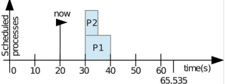
Suppose a non-signed 16-bit timer, maximum 65,535 into a system where two processes are scheduled for the same instant as shown in Figure 2. When the counter matches the one set for each process only one can take control of the CPU and run.
After the execution of the process P1, the only infor-mation available to the kernel is it timer value (now) and the start value for each of the processes as shown in Fig-ure3. Thus it is not possible to know if the process P2 is 10 seconds late or if it was scheduled to occur 50,535 s ahead.
[image:2.595.309.537.519.721.2]There are two solutions to this problem: create a flag for each process, indicating when it is ready to run, or create a counter for each process indicating the remain- ing time to run. All these counters should be decree-
Figure 2. Two processes scheduled to the same time.
[image:2.595.97.248.609.722.2]mented every tick of the kernel, generating more over- head.
On the other hand, if the counter is allowed to assume negative values, it is possible to examine for how long the process is waiting. With this information it is possible to take some action in order to avoid starvation [6]. Through a priority system it is possible to promote the process that is waiting for a long time without being executed.
2.4. Hardware Driver
Fundamentally, a hardware driver is simply a form to abstract out the details of the hardware device so the ap-plication developer does not need to worry about them [12].
This software layer comprises a set of modules im-plemented which provide the necessary mechanisms to access the device specific input/output stream. Thus, the upper layer has a “standard view” of devices with a common programming interface [13]. The device drivers can be loaded dynamically without restarting the kernel [14].
2.5. Hardware Interrupts
The interrupt is a mechanism used to signal, to the CPU, the occurrence of important events related to peripheral devices and other elements of the system [15]. When it occurs, the program execution is stopped and the current program flow is shifted to a specific routine [13]. This routine is commonly called interrupt service routine (ISR).
The interruption allows the peripheral devices to syn-chronize their operation with the CPU or to signal the end of some task. If it did not exist it would be necessary to waste time checking the desired peripheral ended its function or take the risk of inserting a delay in the recep-tion of the informarecep-tion [16].
Access to interruptions, using high-level languages, is done in a complex and non-standard way because each hardware has its own configuration and each compiler provide a different way to access the hardware.
It is important that the code executed within the inter-ruptions to be fast, preventing that the other processes to be stopped for a long time.
2.6. Callback
The callback is a programming technique typically used when a process A requires a return from a process B but does not want to remain idle while waiting for the re-sponse.
Through this technique, the process B obtains a func- tion pointer from the process A. When the execution of the requested service is completed, the process B can
notify the process A by invoking the function pointer provided [17].
This is a very interesting structure to use to avoid lengthy and complex functions to be implemented within the interruptions. The process responsible for each inter-rupt should only perform the essential functions and to leave the heavier processing for a second function that will be executed outside of the interruption. This second function is called via callback technique.
3. Development
In this work it was developed a cooperative microkernel and a device driver controller to isolate the kernel from the drivers. The processes will be scheduled based on their temporal needs, specifically the frequency of execu- tion and the remaining time to its start. The purpose of these options is to simplify the development of a system that includes real-time constraints.
3.1. Process Definition
One process is simply one function that will be executed by the kernel. In order to manage its execution, more information, regarding the process temporal needs, are grouped into one struct. This struct and the pointer func- tion declaration is presented in Code 1.
3.2. Kernel Implementation
The developed kernel has four functions: kernelInit, ker- nelAddProc, kernelClock and kernelLoop. Processes are added in a pool which is implemented as a circular buffer with a predefined size.
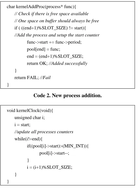
The addition of new processes by the function kerne-lAddProc, can only be achieved if there is enough space in the buffer as can be seen on Code 2. At the time of addition is also important to initialize the new process with appropriate values. It should be noted that the pool is implemented on a circular buffer.
The kernel requires one temporized hardware interrupt to synchronize its operation. This interruption should call the function kernelClock as presented on Code 3. Nega-tive values are allowed to track which functions had
//Pointer function type declaration
typedef char(*ptrFunc)(void);
//Process struct
typedef struct { ptrFunc function; unsigned int period; signed int start; } process;
char kernelAddProc(process* func){
// Check if there is free space available // One space on buffer should always be free
if ( ((end+1)%SLOT_SIZE) != start){
//Add the process and setup the start counter
func->start += func->period; pool[end] = func;
end = (end+1)%SLOT_SIZE; return OK; //Added successfully
}
return FAIL; //Fail
}
Code 2. New process addition.
void kernelClock(void){ unsigned char i; i = start;
//update all processes counters
while(i!=end){
if((pool[i]->start)>(MIN_INT)){ pool[i]->start--;
}
i = (i+1)%SLOT_SIZE; }
}
Code 3. Kernel clock procedure with processes countdown clock.
their start delayed, avoiding conflict situations such as in
Figure3.
The function kernelLoop is responsible for the proc-esses execution. The order in which the procproc-esses will be executed is guided by their temporal needs. They are ranked according to the time remaining to the start of their execution, indicated by the start variable. The ker- nel performs a search among all scheduled processes and wait for the process to be ready to run it. During this time the system can enter a power saving mode, in general it is made with an assembly command as presented on
Code 4.
Figure 4 shows the model of the developed kernel.
This represents all the definitions and decisions taken in the previous steps.
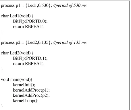
With this kernel is possible to develop a system with tasks that have various time requirements simply. Code 5
presents one example in which two led’s are blinked with different frequencies.
3.3. Drivers
A driver can be defined as a set of functions to access, control and monitor a hardware device. Thus one of the possible options for its implementation is an array of function pointers. Each element on the array provides a
pointer to one functionality to the application. These functions receive as parameter one pointer to void and return one char.
The parameter passing as void pointer is needed be-cause the system does not know in advance the amount or types of variables that will be passed by the kernel. These definitions can be seen on Code 6.
void kernelLoop(void){ unsigned char j; unsigned char next; process* tempProc; for(;;){
if (start != end){
j = (start + 1)%SLOT_SIZE; next = start;
while(j! = end){
// get the smallest start time
if(pool[j].start<pool[next].start){ next = j;
}
// next process
j = (j + 1)%SLOT_SIZE; }
// exchange places on the buffer
tempProc = pool[next]; pool[next] = pool[start]; pool[start] = tempProc; while(pool[start].start>0){
// wait on low power mode
_asm SLEEP_endasm; }
// check if the process needs to be rescheduled
switch (pool[start]->function()) {
case REPEAT:
kernelAddProc(pool[start]); break;
case FAIL:
break;
default: ;
}
// get the next process on the pool
start = (start + 1) % SLOT_SIZE; }
} }
[image:4.595.58.291.83.401.2]Code 4. Kernel scheduler and processes execution.
[image:4.595.307.536.174.680.2]process p1 = {Led1,0,530}; //period of 530 ms
char Led1(void) {
BitFlp(PORTD,0); return REPEAT; }
processp2={Led2,0,135}; //period of 135 ms
char Led2(void) {
BitFlp(PORTD,1); return REPEAT; }
void main(void){ kernelInit(); kernelAddProc(p1); kernelAddProc(p2); kernelLoop(); }
Code 5. Blinking leds example using the developed kernel.
//Pointer function type declaration
typedef char(*ptrFuncDrv)(void *prm);
//Driver struct
typedef struct { char drv_id;
ptrFuncDrv *functions; ptrFuncDrv drv_init; } driver;
// Initialize the driver and return the handle
typedef driver* (*ptrGetDrv)(void);
Code 6. Device driver definition.
The structure of the driver consists of a vector of pointers of ptrFuncDrv and a function pointer apart. The latter is responsible for starting the driver.
In order for the device driver controller to have access to each driver, the driver must implement one more func- tion, which initializes the structure above and returns a handle to the driver, which is implemented as a pointer to the structure. This enables drivers to be loaded and ac-cessed dynamically, not requiring a static link at compile time.
Another required element is one enumerated that de-fines the positions of each function pointer in the vector. By making it as an enumerator, the developer has an easier way to program the device, without adding too much overhead on the system. The enumerator act as a label for each function provided by the driver. Code 7
presents an example of a device driver interface for a generic driver.
This standardization allows the device driver control-ler to work with different drivers regardless of their im-plementation.
3.4. Generic Driver Development
This section presents a generic driver to illustrate the development of one driver. As shown in the pattern on
Code 8 it is necessary to implement function that initial-ize the driver and returns a handler.
The function getDriver is the only function that should be reported to the controller. It is responsible for return-ing the address of the structure that contains the relevant information of the driver and initialize the driver struc-ture.
The model of a generic driver is presented on Figure 5.
From the Figure 5 one can observe that all drivers must include the driver struct in order to allow its access and management by the device driver controller.
//Driver handle
static driver thisDriver;
//Functions array
static ptrFuncDrv this_functions[GEN_END];
enum {
GEN_FUNC1, GEN_FUNC2, GEN_FUNC3, GEN_END };
Code 7. Example of a device driver interface.
driver* getDriver(void) { this.drv_init = initGeneric;
this.functions=(ptrFuncDrv*) &this_functions; return &thisDriver;
}
[image:5.595.60.288.84.275.2]Code 8. Example function to obtain the driver handler.
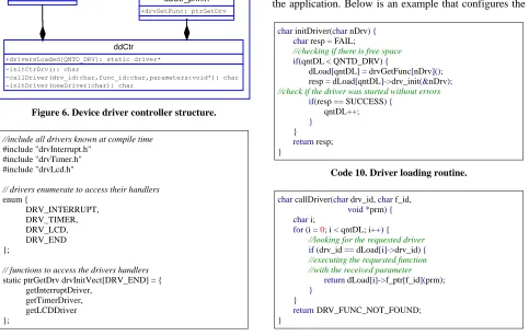
3.5. Device Driver Controller
The device driver controller was designed to intermediate the requests from the application, or the kernel, to the drivers, with minimal overhead. The structure of the con-troller can be seen in Figure6.
The device driver controller needs an access to each driver. This can be done statically by passing all the ptrGetDrv functions to the controller. This functions re-turns a handler, which is a pointer to a driver struct, with all information about the device. If the driver is not known at compile time it must be stored in memory at runtime and a pointer to its structure should be passed to the controller. The static linking is presented at Code 9.
The device driver controller have an array of drivers and a counter indicating how many drivers have been loaded so far. It also has three functions: one to initialize itself, another to load a particular driver and a third one to check the kernel/application command and forward it to the correct driver.
[image:6.595.59.542.420.727.2]Loading a driver is done though the list of known drivers and starting its initialization routine. Only after
Figure 6. Device driver controller structure.
//include all drivers known at compile time
#include "drvInterrupt.h" #include "drvTimer.h" #include "drvLcd.h"
// drivers enumerate to access their handlers
enum {
DRV_INTERRUPT, DRV_TIMER, DRV_LCD, DRV_END };
// functions to access the drivers handlers
static ptrGetDrv drvInitVect[DRV_END] = { getInterruptDriver,
getTimerDriver, getLCDDriver };
Code 9. Device driver controller example.
proper initialization the driver is stored in the list of loaded drivers. If there is no space for another driver or the driver failed to initialize, the function returns an error.
Code 10 presents the driver initialization routine.
All driver calls, originated from the kernel or the ap- plication, are intermediated by callDriver function. This function iterates through the list of loaded drivers searching for the requested device. From Code 11 it can be seen that if the device driver is not found an error code is returned.
3.6. Interrupt Abstract Layer
There are some interesting solutions that help the devel-oper to maintain a high level programming style while still interacting with hardware details. The interrupt ab-straction layer is one of them. This software layer aims to abstract the interrupt routines and still allow the applica-tion developer to access them easily.
This is done through a function pointer that stores the address of the function that the user want to execute in the interrupt context. The interrupt abstraction layer will store this pointer inside itself. This pointer can be changed by the program at runtime even more than once. This allow the developer to select a different routine de-pending on the program context.
With the technique presented on Code 12, the details of low-level compiler instructions become hidden from the application. Below is an example that configures the
char initDriver(char nDrv){ char resp = FAIL;
//checking if there is free space
if(qntDL < QNTD_DRV){
dLoad[qntDL]= drvGetFunc[nDrv](); resp = dLoad[qntDL]->drv_init(&nDrv);
//check if the driver was started without errors
if(resp == SUCCESS) {
qntDL++; } } return resp; }
Code 10. Driver loading routine.
char callDriver(char drv_id, char f_id, void*prm){ char i;
for(i =0; i < qntDL; i++){
//looking for the requested driver
if(drv_id == dLoad[i]->drv_id){
//executing the requested function //with the received parameter
return dLoad[i]->f_ptr[f_id](prm); }
}
returnDRV_FUNC_NOT_FOUND;
}
kernel to call the function timerISR on each hardware interrupt generated by the timer device. Note that there isn’t any microcontroller specific instruction. This way, in order to port the code to another architecture the de-veloper needs only to rewrite the drivers.
Code 13 presents an example of the system making
use of the timer interrupt without the need to deal with the underlying hardware.
3.7. Hardware Devices Callback
In some devices there is the need to wait for a response from the hardware. Reading the A/D converter is an ex-ample: after initialized, it starts the conversion of the analog signal on its input. Without the use of interrupt or a callback technique, the system must wait for the end of conversion, losing processing time that could be used for another task.
A second problem that may arise is the time spent in the interrupt handling routine. It should be as small as possible, preventing the system to lose, or delay, a sec-ond interrupt could not be serviced while the processor is busy with the first one.
// ISR function pointer type definition
typedefvoid(*intFunc)(void);
// Internal variable to store the ISR pointer
static intFunc thisInterrupt;
// Function to configure the ISR pointer
char setInterruptFunc(void*prm){ thisInterrupt =(intFunc) prm;
return OK; }
Code 12. Definition, storage and management of the ISR pointer.
// This function will be called inside the // interrupt routine
void timerISR(void){ kernelClock(); }
void main (void){ kernelInit();
initDriver(DRV_INTERRUPT); initDriver(DRV_TIMER);
// Enabling TMR interrupt
callDriver(DRV_TIMER, TMR_INT_EN,0);
// Setup of the ISR function
callDriver(DRV_INTERRUPT, INT_TIMER_SET, (void*)timerISR);
// Enabling interrupts
callDriver(DRV_INTERRUPT,INT_ENABLE,0); kernelLoop();
}
Code 13. Example of ISR usage.
The solution to these problems can negatively impact on the system performance if not properly implemented. This task is particularly difficult because the routines are very close related to hardware issues and must be devel-oped specifically for each architecture and for each pro-ject.
The development of a callback interface aims to fa- cilitate the use of this tool by the programmer. The best option is to separate the problem into two parts: the first will be executed in the interruption context, being as brief as possible, and the second will be responsible for executing the longer code outside the interrupt context.
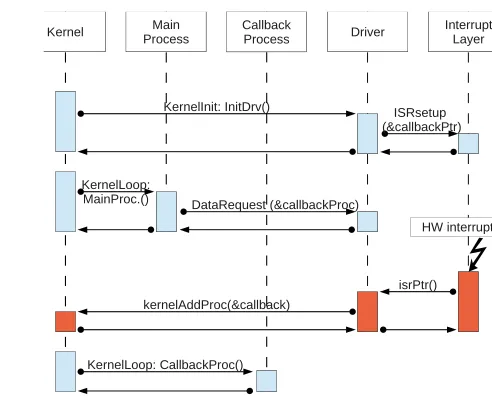
Figure7 shows an event diagram of a system using
the callback.
The first step is setup the driver. The interrupt abstrac-tion layer must be informed about which funcabstrac-tion ( call-backPtr) will be performed during the hardware inter-rupt.
The second step is the callback setup. The main proc-ess must make the necproc-essary adjustments to tell the driver which is the callback process (callbackProc).
When the interrupt occurs, the interrupt driver calls the preset function callbackPtr. The driver performs all the necessary procedures (copying data, set flags, etc.) in order to ensure that the data will be available outside the interrupt context .
Finally, when the kernel and the callback process con-ditions are met, the kernel will run the callback process removing it from the pool of processes. Within the call-back process, one can execute tasks which are more pro- cessing intensive, thus requiring more time, such as sig- nal filtering, data storage on a nonvolatile memory, da- tabase search, processing control/management rules etc.
4. Results
In order to execute the kernel on the test board it is nec-
Main
Process Driver
Interrupt Layer
ISRsetup (&callbackPtr)
DataRequest (&callbackProc)
HW interrupt
isrPtr() Kernel
kernelAddProc(&callback) KernelLoop:
MainProc.()
KernelLoop: CallbackProc() KernelInit: InitDrv()
[image:7.595.57.287.364.479.2]Callback Process
[image:7.595.288.534.522.724.2]essary to develop at least one driver to provide access to a hardware timer interrupt (drvTimer) and two libraries, one to configure the internal registers (fuses) of the mi-crocontroller (config.h) and one with information about the special registers to access and configure the peripher- als (basico.h).
In order to use all the board resources seven other drivers were developed. The proposed final structure is shown in Figure8.
There is no direct link between the kernel and drivers layer, characterizing the operation of the microkernel, where applications are separated from drivers, in this case by the controller drivers.
It can be further noted from Figure8 that all drivers developed are derived from the structure shown in Fig-ure5 in this way the controller can operate any one of them, even without knowing the implementation of each of them at compile time.
Figure9 shows the amount of RAM used by each of
the three layers of a system using the kernel developed. The kernel itself is the largest consumer of RAM. This was expected since he is responsible for inserting, orga-nizing and storing the processes into an internal buffer.
[image:8.595.354.490.179.248.2]As can be seen in Figure10 the final implementation of the controller drivers occupies a small portion of memory compared to the amount of drivers being even smaller than the kernel used. This finding is of great im- portance since the controller is an essential component in systems with microkernel. Also the large consumption of
Figure 8. Complete system diagram.
47%
15% 38% Used RAM memory
Kernel Device Controller Drivers
Figure 9. RAM consumption (total of 999 bytes).
16% 4%
80% Used ROM memory
Kernel
Device Controller Drivers
Figure 10. ROM consumption (total of 14.74 Kb).
the ROM, almost 15 kilobytes can be explained by the high number of drivers and descriptors implemented in this work and the absence of optimization on the com-piler.
5. Conclusions
The developed microkernel allows the programmer to benefit from a layer of abstraction that is generally only available to desktop developers. The proposed scheduler is capable of guaranteeing soft real-time processes only, because the guarantee of real time is not effective in all cases using a cooperative kernel.
The implementation of the device driver controller used few resources of ROM, especially when compared to other components. As a whole, the system consumed few memory resources, an important point for its use in embedded systems, especially the low cost ones.
The proposed standard for writing drivers proved quite simple to use and did not burden too much the drivers access.
The implementation of an effective callback system brought the benefits of using the hardware interrupts without its inherent complexity.
When concerning memory usage, the proposed system proved itself a good candidate to be used on low resource embedded system as proposed in this paper.
The future work of this research is to modify the scheduler of the microkernel for a preemptive system to ensure hard real-time for at least one process. This would allow the use of this microkernel in stricter control ap-plications.
REFERENCES
[1] W. Stallings, “Computer Organization and Architecture,” 8th Edition, Prentice-Hall, Upper Saddle River, 2009.
[image:8.595.58.288.443.718.2][3] P. Marwedel, “Embedded System Design,” 2nd Edition, Springer, Berlin, 2011. doi:10.1007/978-94-007-0257-8
[4] C. L. Liu and J. Layland, “Scheduling Algorithms for Multiprogramming in a Hard Real-Time Environment,”
Journal of the ACM, Vol. 20, No. 1, 1973, pp. 46-61.
doi:10.1145/321738.321743
[5] W. Wulf, E. Cohen, W. Corwin, A. Jones, R. Levin, C. Pierson and F. Pollack, “HYDRA: The Kernel of a Mul-tiprocessor Operating System,” Communications of the ACM, Vol. 17, No. 6, 1974, pp. 337-345.
doi:10.1145/355616.364017
[6] A. Silberschatz, G. Gagne and P. B. Galvin, “Operating System Concepts,” 8th Edition, Willey, New York, 2009.
[7] M. Barr, “Programming Embedded Systems: With C and GNU Development Tools,” 2nd Edition, O’Reilly, 2006.
[8] A. S. Tanenbaum, J. N. Herder and H. Bos, “Can We Make Operating Systems Reliable and Secure?”
Com-puter, Vol. 39, No. 5, 2006. pp. 44-51.
[9] J. Liedtk, “Improving IPC by Kernel Design,” SOSP’93
Proceedings of the 14th ACM Symposium on Operating
Systems Principles, Asheville, 5-8 December 1993, pp.
175-188.
[10] N. G. Leveson, “Software Safety in Embedded Computer Systems,” Communications of the ACM, Vol. 34, No. 2, 1991, pp. 34-46. doi:10.1145/102792.102799
[11] R. M. A. Almeida, “Questões Temporais para Implemen-tação de Um Microkernel,” 2011.
https://sites.google.com/site/rmaalmeida/extra/pic18fkern el-04
[12] D. Abbott, “Linux for Embedded and Real-Time Applica-tions,” 2nd Edition, Newnes, Wolgan Valley, 2006.
[13] R. S. de Oliveira, A. da S. Carissimi and S. S. e Toscani, “Sistemas Operacionais,” 2nd Edition, Sagra-Luzzatto, 2001.
[14] D. P. Bovet and M. Cesati, “Understanding the Linux Kernel,” 2nd Edition, O’Reilly, 2006.
[15] K. W. Batcher and R. A. Walker, “Interrupt Triggered Software Prefetching for Embedded CPU Instruction Cache,” Proceedings of the 12th IEEE Real-Time and
Embedded Technology and Applications Symposium,
Washington DC, 4-7 April 2006, pp. 91-102.
[16] R. V. Aroca, “Análise de Sistemas Operacionais de Tempo Real para Aplicações de Robótica e Automação,” Masters Dissertation, Universidade de São Paulo, São Paulo, 2008.
[17] F. Dabek, N. Zeldovich, F. Kaashoek, D. Mazières and R. Morris, “Event-Driven Programming for Robust Soft-ware,” Proceedings of the 10th Workshop on ACM
SI-GOPS European Workshop, ACM, New York, 2002, pp.