Tentative Study and Examination of different Tube
Geometry with Helix Angle 600 Double Pipe Heat
Exchanger for Parallel Flow
Sanjay KumarKoli
Assistant Professor, Mechanical Engineering, All Saints College Of Technology Bhopal, India
Abstract: Heat exchanger is a apparatus or equipment, which is use to transfer heat between two fluid which may be in direct contact or indirect contact. We find lots of applications of heat exchangers in our day today life. For example condensers and evaporators are used in boilers, condensers, air coolers and chilling towers etc. Likewise, heat exchangers are used in automobiles sectors are in the form of radiators and oil coolers inside engines.
The straight copper tube, steel tube heat exchanger is manufactured in heat & mass transfer lab and this experiment held at college lab. Straight copper tube and steel tube is the main part of the Practical setup of same length of 1.5 meter made by copper metal tube and steel metal tube of 10 mm inner diameter and 12 mm outer diameter of both tube. In my research work i will find out from experimental observation for effectiveness, Logarithmic mean temperature difference and overall heat transfer coefficient, variation due to cold water and hot water mass flow rates.
Effectiveness decreases with increase in mass flow rate of hot water. Effectiveness increase when mass flow rate of hot water is constant for all the tubes. Average effectiveness of corrugated tube is greater than the straight steel tube and straight copper tube. In both the cases LMTD of all the tubes increase and the value of LMTD of corrugated tube is greater than the straight steel tube and straight copper tube. Overall heat transfer coefficient of corrugated tube gradually increases with increase in mass flow rate of hot water and its value is higher at 90 LPH.
Keywords: Heat exchanger, Condenser, Evaporator, LMTD, NTU, Effectiveness, Fouling factor, corrugated surface, overall heat transfer coefficient, helix angle
I. INTRODUCTION
Heat exchanger is a device or equipment, which is use to transfer heat between two fluid which may be in direct contact or indirect contact. We find lots of applications of heat exchangers in our day today life. For example condensers and evaporators are used in boilers, condensers, air coolers and chilling towers etc. Likewise, heat exchangers are used in automobiles sectors are in the form of radiators and oil coolers inside engines. Heat exchangers are also used widely in chemical sectors and process sectors for transmitting the heat between two fluids which are at a single or two states.
A. Various types of heat Exchangers 1) According to Heat Transfer Process a) Direct Contact Type
b) Transfer Type Heat Exchanger
c) Regeneration type Heat Exchanger
2) According to Constructional Features a) Tubular Heat Exchanger
b) Shell and Tube Heat Exchanger
c) Finned tube Heat Exchanger
3) According to Relative Direction of Fluid, a) Parallel flow
b) Counter flow
4) According to Heat transfer Process
a) Direct Contact Type Heat Exchanger: Direct contact type heat exchangers are that type heat exchanger in which two immiscible fluids are directly mixed with each other to transmit heat between two fluids. The efficiency of this type of heat exchanger is more as compared to other type heat exchangers. Cooling towers, jet condenser, de-super heaters, open feed water heater are examples.
Fig.1.1: Direct contact type heat exchanger
b) Transfer Type and Recuperator Type: Transfer type or Recuperates type heat exchanger are those type of heat exchangers in which two fluidsflow simultaneously through two tubes separated by walls.
c) Regenerative Type Heat Exchanger: The hot and cold fluid flow alternately on same surface. During the hot fluid transfer through the wall of exchanger gets heated and when the cold fluid flow through it, this heat passed by the wall of the heat exchanger to the cold fluid so that the temperature of cold fluid increases. The common examples are pre-heaters for steam power plant, blast furnace etc.
5) According to Constructional Features
a) Tubular Heat Exchangers: In these type of Heat Exchangers tubes are positioned concentric to each other and two fluid flows in two tubes separated by wall. These are generally used in most of the engineering application.
b) Shell and Tube Type Heat Exchanger: In these types of Heat Exchangers consists of shell and lots of parallel tubes. The heat transmission takes place when one fluid flow through the tube and other fluidflow outside the tube inside the shell of the exchanger this type of heat exchanger have large surface area to volume. Baffles plates are provided to enhance the turbulence hence increases the heat transfer rate.
For improving the heat transfer rate fins are placed on the outer surface of the heat exchangers. These are generally use in gas to liquid type heat exchanger and fins are generally placed in gas side. These are use in gas turbines, automobiles, aeroplane, heat pump etc.
6) According to flow of Fluid Arrangement (According to Relative Direction of Fluid)
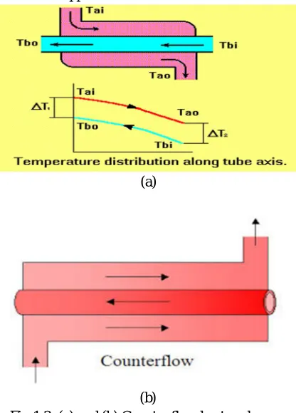
a) Parallel Flow Type Heat Exchanger: Two fluids flow parallel to each other, it means they flow in same direction. These are also known as concurrent heat exchanger.
(b)
Fig 1.2: (a) and (b) parallel flow heat exchanger
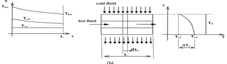
b) Counter Flow Heat Exchanger: Two fluid flow in opposite direction to each other.
(a)
(b)
Fig 1.3: (a) and (b) Counter flow heat exchanger
c) Cross Flow Type Heat Exchanger: When two fluidsflow perpendicular to each other. This is further categorised in to mixed flow type and unmixed flow type heat exchanger.
[image:3.612.200.408.88.231.2] [image:3.612.220.428.271.561.2](b)
Fig 1.4: (a) and (b) Cross flow heat exchanger
B. Heat Transfer Enhancement
Working for the goal of saving energies and to make compact the design for mechanical and chemical devices and plants, the enhancement of heat transfer is one of the key factors in design of heat exchangers. Heat transfer enhancement techniques are generally categorised in two types.
C. Heat Transfer Enhancement Method
Geometry heat transfer coefficient (overall heat transfer coefficient) depends on different parameters like orientation of heat exchanger, geometry of heat exchanger, properties of fluid flow, type of fluid like laminar and turbulent, material of tube etc. As it is seen that heat transfer in case of turbulent flow is always greater than the transfer of heat in laminar flow. Heat transfer rate can be increased by producing turbulence effect in fluid flow. Turbulence can be created by two ways.
1) Active Methods: These techniques are more complex in use and design point of view as these methods require some external power input to cause the desired flow amendment and progress in rate of heat transfer. It has limited application because of the require of external power in many practical applications. In comparison with passive techniques, this technique has not shown much potential as it is difficult to give external power input in lots of cases.
In these cases, external power is use to assist the desired flow amendment and the associated improvement in the rate of heat transfer.
II. LITERATURE REVIEW
1) Zaid S. Kareem et al (2015)[ 1]:A Computational Fluid Dynamics was employed for water flowing at low Reynolds number in spiral corrugated tubes. This article aimed for the determination of the thermal performance of unique smooth corrugation profile. The Performance Evaluation Criteria were calculated for corrugated tubes, and the simulation results of both Nusselt number and friction.
2) Xuemei Su et al (2015) [2]: Experimentally investigated that at two mass flow of 147.2 kgm-2s -1and 191.5kgm-2 s-1and fluxes ranges from 9023Wm-2 to 39051Wm-2of saturated LN2 corrugated stainless steel horizontal tube are investigated, due to area augmentation the heat transfer is enhanced as and increase with increase heat flux and mass flow flux the local heat transfer coefficient increases and strong dependence on heat flux.
3) Ki JungRyu et al(2015) [3]: Analysed the performance of heat exchanger, by report on heat transfer and fluid flow correlation use corrugated louvered fins .With respect to the ratio of the fin pitch to the louver pitch (Fp/L/pc)col burn factor j and Friction factor f is investigated. The j and f correlations independent of Ll/Fl in the range 0.8 <Ll/Fl< 0.9, because the changes in the pressure-drop and heat-transfer characteristics were small (±5%).We also established the flow efficiency g correlation, which is applicable for 0.3 <Lp sin La/Fp< 0.7 in 100 < Re < 3000 within an error of ±15%.
4) Hamed Sadighi Dizaji et al (2015) [4]: experimentally investigated that the outcome of heat flow, thermodynamically and geometrically characteristics on exergy loss in shell and coiled tubes heat exchangers. Pressure drop and heat transfer characteristics in shell and coiled tube heat exchangers have been widely studied. Exergy loss increases with the increase of shell or coil side flow rate. Dimensionless exergy loss can increase or decrease with the increase of flow rates. It depends on Cmin. Both of the exergy loss and dimensionless exergy loss increase with the increase of coil side inlet temperature and decrease of shell side inlet temperature.
[image:4.612.118.505.87.197.2]energy conversion. Nano fluids are advanced and potential coolants, which can provide appropriate thermal performance in heat exchange devices. In this paper, fluid flow and heat transfer characteristics of Cu–water nanofluid inside five serpentine tubes with variable straight section lengths are experimentally investigated. The concentrations of 0%, 0.1%, and 0.4% wt. of stabilized Cu–water Nano fluid are examined with variation of flow rates in the range of 1–5 l/min. The Cu–water nano fluids are produced by a one-step method, namely electro-exploded wire (EEW) technique, and the thermo-physical properties of the nano fluids required for the analysis are systematically measured. To obtain accurate results, a highly precise
6) Vamsi Mokkapati et al (2014) [6]: The purpose of this work is to investigate gas to liquid heat transfer performance of concentric tube heat exchanger with twisted tape inserted corrugated tube and to evaluate its impact on engine performance and economics through heat recovery from the exhaust of a heavy duty diesel generator (120 ekWrated load).A study to improve the effectiveness of a diesel exhaust heat recovery System (concentric tube heat exchanger) of Ruby, Alaska has been Conducted. The improved system is the original heat exchanger inserted with a twisted tape. The goal of the present work is to maximize the heat recovery rate by optimizing the design of twisted tape insert. The physical size of the heat exchanger, twist ratio and exhaust back pressure change are the constraints. In this study, the outer tube is a plain tube and the inner tube is an annularly corrugated tube with and without twisted tape inserts. The following paragraphs summarize the findings obtained from this study.
7) Ji Chan Park et al (2014) [7]: It analyzed, copper catalyst coated metallic foam and heat exchanger type reactor was developed with the consideration of the severe heat and mass transfer limitations in the Fischer–Tropsch synthesis reaction. The system showed highly desirable results not only in terms of its lowCH4 and CO2 selectivity’s, but also its high productivity, because of its enhanced heat and mass transfer properties in the reaction. The CO conversion decreased, but the C5+ selectivity increased, with increasing synthesis gas flow rate, because the former was strongly affected by the reaction contact time and the latter was deeply related to the superficial velocity of the synthesis gas in the reactor. Furthermore, this system effectively prevented the formation of CH4, even at high temperature, and reduced the diffusion restrictions of the hydrocarbons produced in the catalyst pores with the temperature.
8) Dillip Kumar Mohanty et al (2014) [8]: Analysis of heat exchanger fouling using previous data of a shell and tube heat exchanger has been found to be a very useful methodology to predict and consequently improve the overall performance of a process plant involved with such systems. The developed fouling prediction model provides a priori picture about the fouling
9) Cong Chen et al(2013) [9]: Had analyzed for enhanced heat transfer of mixed molten hitec salt in corrugated tubes with three different sets of structural parameters. Experimentally find out that smooth tube and transversally corrugated tube, the drag coefficient for transversally corrugated tubes, is larger than the smooth tube. Correlations between drag coefficient and Re number were obtained for transversally corrugated tubes with different parameters and for smooth tubes. The drag coefficient for transversally corrugated tubes is larger than that for smooth tubes, and the drag coefficient for tubes of smaller pitch is larger than that for tubes of larger pitch.
10) Shriram S. et al (2013) [10]: It observed that the Al2O3is a promising candidate for the enhancement of overall convective heat transfer coefficient of water. The heat transfer characteristics of nano fluids improve with Reynolds number significantly as compared to base fluids. For same range of Reynolds number, addition of nano particles to the base fluid enhances the heat transfer performance and results in higher heat transfer coefficient than that of the base fluid. The heat exchanger is fabricated from copper concentric inner tube with a length of 1000 mm.
11) Zan Wu et al (2013) [11]: For both laminar flow and turbulent flow, no anomalous heat transfer enhancement was found. The heat transfer enhancement of the nano fluids compared to water is from 0.37% to 3.43% according to the constant flow velocity basis. Figure of merit based on the constant Reynolds number can be misleading and should not be used for heat transfer enhancement comparison. Additional possible effects of nano particles, e.g., on the convective heat transfer characteristics of the nano fluids are insignificant compared to the dominant thermo physical properties of the nano fluids. The heat transfer enhancement of the five nano fluids over tap water ranges from 0.37% to 3.43% for the constant flow velocity basis for both laminar and turbulent flows. Figure of merit based on the constant Reynolds number can be misleading and should not be used to evaluate heat transfer enhancement because the net result.
12) XuXiu-qing et al (2013) [12]: The corrosion rate reached the maximum of 0.195 mm/a when the medium temperature was 60
13) CarstenSchroer et al (2012) [13]: Specimens cut from two different sample materials of T91 ferritic /martensitic steel were exposed for up to8000 h to flowing oxygen-containing lead–bismuth eutectic (LBE) at 450 _C, 2 m/s flow velocity and oxygen concentration averaging 1.1 _ 10_6 mass%. Under these conditions, T91 forms an essentially bi-layer corrosion scale consisting of magnetite and iron–chromium spinel, whose thickness as a function of exposure time was measured in the light-optical microscope. The accompanying metal recession was assessedin dependently by a metallographic method as well. The quantitative data was analysed using different kinetic laws, in consideration of the results of electron-microscopic investigations and energy-dispersive X-ray micro-analyses of the scale.
14) NavidParnian et al (2012) [14]: Carryover of caustic soda (NaOH) in the steam path caused catastrophic failure of super heater 304Hstainless steel tubes in a gas fired heater and led to an unexpected shutdown after just 5 months of continuous service following the start of production. The cause of the failure was studied, with a focus on the effect of caustic embrittlement on stress corrosion cracking (SCC). The cracks were examined at the seam weld, heat affected zone (HAZ), and U-bend areas. Hardness was measured for the base metal, HAZ, and weld metal, and microstructures were examined using optical microscopy and scanning electron micros copy (SEM). Crack initiation is attributed to gouging on the precipitated carbide at the HAZ and also the formation of sigma phase in the weld metal, as shown by energy dispersive X-ray (EDX) analysis. [2,23–26], and according to the findings of this research, the formation.
15) S. Pethkool et al (2011) [15]: had investigated experimentally heat transfer enhancement and friction factor with nine helically corrugated tube with three different pitch –to-diameter ratios (p/DH=0.18,0.22, and 0.27)and three rib-height to diameter ratios(e/DH=0.02,0.04 and 0.06). It is found that the friction factor and thermal performance factor increase with increasing the Pitch ratio (P/DH) and the rib-height ratio (e/DH). Behaviors of the exchanger over the next period of operation. It observed that maximum error is found to be 1.25% during training phase and 0.064% during the testing phase..
16) Zachar et al (2010) [16]: had done the experiment to improve the inside heat transfer rate by examine of different geometrical parameters of helical corrugation on the outer surface of helically coiled-tube heat exchangers. It analyzed that the heat transfer rate is almost independent from the inlet temperature and the outer surface temperature
17) Milind V. Rane et al (2005) [17]: Analysed by tube-tube and double wall tubular heat exchanger two or more tubes are placed side-by-side and bonded thermally using thermal bonding material (TBM) for effective heat transfer. In case of serpentine layout tube-tube (TTHE), the experimental results indicate that there is a definite optimum for a number of bends for a particular application.
III. METHODOLOGY
This lesson deals with the experimental methodology, method for calculating effectiveness, LMTD and overall heat transfer coefficient formulas used in calculation given in this part. Mathematical calculation and value gained for straight copper tube parallel flow, Straight Steel tube parallel flow and straight Corrugated tube parallel flow at 600 are shows in appendix.
A. Experimental Methodology
1) Flow rates in the tube and in the shell were varied. The following Six levels were used: 15, 30, 45, 60, 75 and 90 LPH. All possible combinations of these flow rates in shell and the inside the tube were tested.
2) These were done for three heat exchangers “Straight steel tube, Straight Copper tube heat exchangers and corrugated tube heat exchanger” in parallel flow arrangement.
3) The Temperature data used in the mathematical calculation was after the system had stabilized. The type-K thermocouples used for temperature value. All the thermocouples were constructed from the same thermocouple wire, and hence the repeatability of temperature value was high with temperature reading fluctuations within ±0.3 °C.
4) Water properties used at mean temperature of 450C.
B. Heat Exchanger Study
1) Heat exchangers usually operated for long interlude of time without change in their operating conditions. Therefore, they can be modelled as steady flow devices.
3) In particular, if the water ate not undergoing the phase change, the first law of the thermodynamics states that the rate of heat transmission from the hot fluid be equals the rate of heat transfer to the cold fluid.
4) The rate of heat transfer by hot fluid is given by:
= ℎ ( − ) … … … (1)
5) The rate of heat transfer to cold fluid is given by:
= ( − ) … … … (2)
6) It is very simple to use LMTD method of heat exchanger study when inlet and outlet temperatures, mass flow rates for hot and cold water and overall heat transfer coefficient are available or easily be determines from specified relations. The heat transfer surface area and thus size of heat exchanger can easily be determined from given equation.
= ∆
C. LMTD for Parallel Flow Heat Exchanger
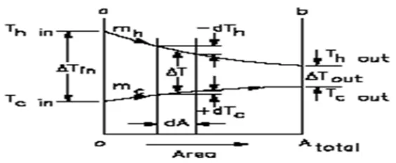
Now consider a parallel flow double pipe heat exchanger as shown in fig 3.1 the temperature difference∆T between hot and cold water is large at the inlet of heat exchanger and it decreases and that of cold fluid increases along the length of heat exchanger, thus the temperature of cold fluid can never exceed that of hot fluid In any case.
Applying the energy balance to differential elements in hot and cold water. The rate of heat transfer from hot water
=−
and for cold water fluid
= +
The temperature difference of hot fluid is a negative quantity and negative sign is added to equation to make the heat transfer rate
‘ ’ a positive quantity. Let for differential surface area ‘ ’ the temperature difference ∆ between hot and cold fluid is expressed as;
∆ = − ………. (3) In differential form:
[image:7.612.158.440.430.546.2](∆ )= −
Fig. 3.1 Temperature distribution for a parallel flow
)
4
...(
mhCph
Q
dTh
)
5
...(
mcCpc
Q
dTc
Substitute the values of & from equation (4) and (5) we get
(∆ ) =− + … … … . ( 6 )
The heat transfer t= rate across the differential surfaces area of heat exchanger can also be expressed as
Using in equation we get
(∆ ) =− ∆ + … … … . ( 7 )
Integrating equation from inlet to outlet condition of the heat exchanger.
UBA T
T
1 2
ln
… … . … … … … . ( 8 )
Substituting values of ℎ, ℎ and , from above equation we get
ln ∆
∆ = + … … … … . ( 9 )
=
Comparing above expression with equation we get. The∆ iscalled the log mean temperature difference, which is suitable form of temperature difference for tubular heat exchanger. Where ∆ and ∆ represent thetemperature difference between hot and cold water at two ends (inlet and outlet)of a heat exchanger.
Using equation of the heat transfer rate in double pipe heat exchanger can be expressed as:
Q = UA∆ = U A ∆ … … … . ( 1 0 )
D. The Effectiveness NTU Method
Exchanger are specified and for prescribed mass flow rates, if only inlet temperatures of both water are known and outlet temperatures are to be determined as shown in fig. 3.2 then use of LMTD method is restricted. If it is used in such case, then the procedure procedure would require tedious iterations this is not practical. On order to eliminate such complication from the solution, keys and London came up with new method that is called the effectiveness NTU method.
E. Heat Exchanger Effectiveness
It is a dimensionless parameter and defined as the ratio of actual heat transfer rate ' ′ by heat exchanger to maximum possible heat transfer rate ′ ' it is denoted by 'ε'
--- (11)
The actual heat transfer rate in a heat exchanger can be determined from an energy balance on hot and cold water and can be expressed as
= ( − ) = ( − )--- (12) Where'
= and ℎ = ℎ ℎ are heat capacity rates of cold and hot water respectively.
In a heat exchanger objective is to either maximization of heating or cooling i.e to gain the maximum temperature difference and hence the maximum heat transfer rate can be determined with maximum temperature difference in a heat exchanger. The maximum temperature difference is the difference between inlet temperatures of hot and cold water.
That is,
∆ = --- (13)
A heat exchanger will reach its maximum possible temperature difference (Thi — Tci)when (1) the cold fluid is heated to inlet temperature of hot fluid, or (2) the hot fluid is cooled to inlet temperature of cold fluid. Such conditions can be achieved in counter flow heat exchanger of infinite length; these conditions will not reach simultaneously unless the heat capacity rates of both water are equals ( ℎ = ).
When the heat capacity rates are not equal, one water having minimum value of heat Capacity rate ( m Cp)can experience
maximum temperature difference.
Where, Cminis the smallest value among Cc a nd Cheither for cold or hot water depending on product of mass flow rate and
specific heat.
max
)
(
max
)
(
max
Q
Tho
Thi
mhCph
Q
Tci
Tco
mcCpc
Q
For cold water,
E f fe ct i v en es s,
)
min(
)
(
)
min(
)
(
Tci
Thi
C
Tci
Tco
Cc
Tci
Thi
mCp
Tci
Tco
mcCpc
- - - ( 1 4 )
No w for hot water,
ε =
)
min(
)
(
)
min(
)
(
Tci
Thi
C
Tho
Thi
Ch
Tci
Thi
mCp
Tho
Thi
mhCph
If the effectiveness εThi, Tc, and minimum heat capacity Cm i nare known, the actual heat transfer rate can be obtained as
= ( − )
1) Capacity Ratio
In heat exchanger study, it is convenient to define a dimensionless parameter called capacity ratio is given by.
= ℎ
ℎ =
For any heat exchanger, the effectiveness is the function of NTU and heat capacity.
F. Experimental Setup
This chapter covers the fabrication of Practical setups used to generate the sufficient data for comparative analysis of straight copper tube, straight steel tube and corrugated steel tube heat exchangers. Sufficient data was generated by varying different parameters over predetermined ranges. The instrumentation used and the data collection technique adopted are also discussed in this chapter
G. Specifications of Straighttube Heat Exchanger
IV. RESULTS AND DISCUSSION
In this part, result find out from experimental observation for effectiveness, Logarithmic mean temperature difference and overall heat transfer coefficient, variation due to cold water and hot water mass flow rates.
Straight Steel Plain Tube Heat Exchanger When hot Water is Fixed at 45 LPH in Parallel Flow Arrangement:- Sr . N o. Mas sflo w Rate of Hot Wat er (Mh ) (LP H) Massfl ow Rate of Hot Water Mh (Kg/Se c)
Mh X
CPh
(W)
Thot(
inlet ) (oC)
Thot
(Out let) (oC)
∆Th o
(Thi
– Tho)
Mas sflo w rate of Col d wat er (Mc ) (LP H) Mas sflo w rate of Col d wat er Mc (Kg/ Sec) Mc X CP C (W) Tco ld(i nle t) (o C) Tcold (Out let) (oC)
∆T C (Tci n –
Tcou t)
Effec tiven ess (ϵ)
Log arith m mea n Tem pera ture Diff eren ce (LM TD) (∆ ∆ (∆∆ Ove rall heat Tra nsfe r Co-effic ient
1 45 0.0125 0.052 66.5 56.8 9.7 15 0.00 41
0.01 74
31.
2 52.2 21.0 0.23 15.0
6 504.
2
2 45 0.0125 0.052 66.5 53.5 13 30 0.00 83
0.00 35
31.
2 44.8 13.6 0.32 18.9
9 551.
3
3 45 0.0125 0.052 66.5 53.5 13 45 0.01 25
0.05 23
31.
2 41.3 10.1 0.32 21.7
4 491.
7
4 45 0.0125 0.052 66.5 51.7 14.8 60 0.01 66
0.06 74
31.
2 41.1 9.9 0.41 20.5
3 666.
3
5 45 0.0125 0.052 66.5 49.7 16.8 75 0.02 08
0.08 70
31.
2 37.3 6.1 0.38 21.8
8 569.
7
6 45 0.0125 0.052 66.5 49.6 16.9 90 0.02 50
0.10 46
31.
2 36.4 5.2 0.38 22.4
6 562.
V. RESULTS AND DISCUSSION
Straight Steel Plain Tube Heat Exchanger When hot Water is Fixed at 45 LPH in Parallel Flow Arrangement:-
Sr. No. Mass flow Rate of Hot Wate r (Mh) (LPH ) Massflo w Rate of Hot Water Mh (Kg/Sec)
Mh X CPh (W)
Thot(i nlet) (oC)
Thot (Outl et) (oC)
∆Tho
(Thi – Tho)
Mass flow rate of Cold water (Mc) (LPH ) Mass flow rate of Cold water Mc (Kg/ Sec) Mc X CPC (W) Tcol d(in let) (oC )
Tcold (Outl et) (oC)
∆TC
(Tcin – Tcout)
Effecti veness
(ϵ)
Loga rithm mean Temp eratur e Diffe rence (LM TD) (∆ ∆ (∆ ∆ ) Over all heat Trans fer Co-effici ent
1 45 0.0125 0.052 66.5 56.8 9.7 15 0.004
1
0.017 4
31.
2 52.2 21.0 0.23 15.06 504.2
2 45 0.0125 0.052
66.5
53.5 13 30 0.008
3
0.003 5
31.
2 44.8 13.6 0.32 18.99 551.3
3 45 0.0125 0.052
66.5
53.5 13 45 0.012
5
0.052 3
31.
2 41.3 10.1 0.32 21.74 491.7
4 45 0.0125 0.052
66.5
51.7 14.8 60 0.016
6
0.067 4
31.
2 41.1 9.9 0.41 20.53 666.3
5 45 0.0125 0.052
66.5
49.7 16.8 75 0.020
8
0.087 0
31.
2 37.3 6.1 0.38 21.88 569.7
6 45 0.0125 0.052
66.5
49.6 16.9 90 0.025
0
0.104 6
31.
Table: 5.2. Straight Steel Plain Tube Heat Exchanger When Cold Water is Fixed at 45
A. LPH in Parallel Flow Arrangement
Specific heat of Water (CP) =4.18 KJ/Kg.k
Comparative analysis of effectiveness when cold water is constant at 45 LPH for straight steel tube, straight copper tube and corrugated tube with 600 helix angle heat exchanger in parallel flow arrangement.
0 0.2 0.4 0.6 0.8 1
0 20 40 60 80 100
EF FE C TI V EN ES S
HOT WATER MASS FLOW RATE IN (LPH)
EFFECT OF HOT WATER FLOW RATE ON EFFECTIVNESS WHEN COLD WATER
IS KEPT CONSTANT
WHEN COLD WATER FLOW RATE IS 45 LPH
STRAIGHT STEEL TUBE PARALLEL FLOW
STRAIGHT COPPER TUBE PARALLEL FLOW
CORRUGATED TUBE PARALLEL FLOW FLOW Sr. No . Mass flow Rate of cold Water
(Mc) (LPH) Mass flow Rate of cold Water Mc (Kg/Sec)
Mc X CPc(W )
Tcold (inle t) (oC)
Tcold (Outlet
) (oC)
∆Tcold
= (Tcou t – Tcin) Mass flow rate of Hot water
(Mh) (LPH ) Mass flow rate of Hot water Mh (Kg/Sec )
MhXC Ph(W)
Thot (inlet)
(oC)
Thot (Outlet
) (oC)
∆Th
=(Thin – Thout)
Effecti veness (ϵ)
Logarith m mean Temper ature Differen ce (LMTD ) (∆ ∆ ) (∆∆ ) Overall heat Transfe r Co-efficien t
1 45 0.0125 0.052 31.5 49.3 17.8 15 0.0041 0.0171 66.5 57.8 8.7 0.902 18.72 511.31
2 45 0.0125 0.052
31.5 47.3 15.8 30 0.0083 0.0347 66.5 53.9 12.6 0.520 17.02 658.31
3 45 0.0125 0.052
31.5 44.3 12.8 45 0.0125 0.0523 66.5 53.1 13.4 0.374 18.97 555.60
4 45 0.0125 0.052 31.5 37.6 6.1 60 0.0166 0.0695 66.5 49.7 16.8 0.305 21.56 609.40
5 45 0.0125 0.052
31.5 43.4 11.9 75 0.0208 0.0870 66.5 54.7 11.8 0.270 20.96 696.09
6 45 0.0125 0.052
Comparative analysis of effectiveness when hot water is constant at 45 LPH for straight steel tube straight copper tube and corrugated tube with 600 helix angle heat exchanger in parallel flow and counter flow arrangement.
Comparative analysis of Logarithm mean temperature difference when Hot water is constant at 45 LPH for straight steel tube, straight copper tube and corrugated tube with 600 helix angle heat exchanger in parallel flow arrangement.
0 0.1 0.2 0.3 0.4 0.5 0.6 0.7 0.8
0 20 40 60 80 100
EF
F
EC
TI
V
EN
ES
S
COLD WATER MASS FLOW RATE IN (LPH)
EFFECT OF COLD WATER FLOW RATE ON EFFECTIVNESS WHEN HOT WATER
MASS FLOW RATE KEPT CONSTANT
WHEN HOT WATER FLOW RATE IS 45 LPH
STRAIGHT STEEL TUBE PARALLEL FLOW
STRAIGHT COPPER TUBE PARALLEL FLOW
CORRUGATED TUBE PARALLEL FLOW
0 5 10 15 20 25 30
0 20 40 60 80 100
L.
M
.T
.D
COLD WATER MASS FLOW RATE (LPH)
EFFECT OF COLD WATER FLOW RATE ON L.M.T.D WHEN HOT WATER MASS
FLOW RATE KEPT CONSTANT
WHEN HOT WATER FLOW RATE IS 45 LPH
STRAIGHT STEEL TUBE
PARALLEL FLOW
STRAIGHT COPPER TUBE
PARALLEL FLOW
Comparative analysis of Overall heat transfer Coefficient when hot water is constant at 45 LPH for straight steel tube, straight copper tube and corrugated tube with 600 helix angle heat exchanger in parallel flow arrangement.
0 100 200 300 400 500 600 700 800 900 1000
0 20 40 60 80 100
O
V
E
R
A
L
L
H
E
A
T
T
R
A
N
S
F
E
R
C
O
E
F
FI
C
IE
N
T
COLD WATER MASS FLOW RATE IN (LPH)
EFFECT OF COLD WATER FLOW RATE ON OVERALL HEAT
TRANSFER CO-EFFICIENT WHEN HOT WATER MASS FLOW
RATE KEPT CONSTANT
WHEN HOT WATER FLOW RATE IS 45LPH
STRIAGHT STEEL TUBE PARALLEL FLOW
STRAIGHT COPPER TUBE PARALLEL FLOW
CORRUGATED TUBE PARALLEL FLOW
VI. CONCLUSION
An experimental study on straight steel tube, straight copper tube and straight corrugated steel tube of groove angle 600was performed in heat exchanger test lab. Tubes used for the experiment having same diameter and same length. Experiment carried out for all the tubes for same mass flow rate and the water used for the experiment was water.
A. Conclusion Of Present Study
Effectiveness decreases with increase in mass flow rate of hot water. Effectiveness increase when mass flow rate of hot water is constant for all the tubes. Average effectiveness of corrugated tube is greater than the straight steel tube and straight copper tube. In both the cases LMTD of all the tubes increase and the value of LMTD of corrugated tube is greater than the straight steel tube and straight copper tube.
Overall heat transfer coefficient of corrugated tube gradually increases with increase in mass flow rate of hot water and its value is higher at 90 LPH.
REFERENCES
[1] Zaid S. Kareem,M.N. MohdJaafar, Tholudin M. Lazim, Shahrir Abdullah , Ammar F. Abdulwahid (2015) Passive heat transfer enhancement review in corrugation. Experimental Thermal and Fluid Science 68 (2015) 22–38.
[2] Xuemei Su a, Xingya Chen a, Jionghui Liu a, Shuangtao Chen a, Yu Hou. Experimental investigation of forced flow boiling of nitrogenin a horizontal corrugated stainless steel tube, Cryogenics 70 (2015) 47–56.
[3] KijungRyu, Kwan-Soo Lee, Generalized heat-transfer and fluid-flow correlations for corrugatedlouvered fins, International Journal of Heat and Mass Transfer 83 (2015) 604–612.
[5] Morteza Khoshvaght-Aliabadi , Ahmad Alizadeh, An experimental study of Cu–water nanofluid flow inside serpentinetubes with variable straight-section lengths, Experimental Thermal and Fluid Science 61 (2015) 1–11.
[6] Ji Chan Park, Nam Sun Roh, Dong Hyun Chun, Heon Jung, Jung-II Yang, Cobalt catalyst coated metallic foam and heat-exchanger type reactor for Fischer– Tropsch synthesis, Fuel Processing Technology 119 (2014) 60–66.
[7] Dillip Kumar Mohanty , Pravin M. Singru, Fouling analysis of a shell and tube heat exchanger using local linear wavelet neural network, International Journal of Heat and Mass Transfer 77 (2014) 946–955.
[8] Cong Chen, Yu-Ting Wu⇑, Shu-Tao Wang, Chong-Fang Ma, Experimental investigation on enhanced heat transfer in transversally corrugated tube with molten salt, Experimental Thermal and Fluid Science 47 (2013) 108–116
[9] Shriram S. Sonawane ⁎, Rohit S. Khedkar, Kailas L. Wasewar, Study on concentric tube heat exchanger heat transfer performance using Al2O3 – water based nanofluids, International Communications in Heat and Mass Transfer 49 (2013) 60–68.
[10] Zan Wu, Lei Wang, Bengt Sundén, Pressure drop and convective heat transfer of water and nanofluids in a double-pipe helical heat exchanger, Applied Thermal Engineering 60 (2013) 266e274.
[11] Xu Xiu-qinga,b,∗, Bai Zhen-quana, Feng Yao-ronga, Ma Qiu-ronga, Zhao Wen-zhen, The influence of temperature on the corrosion resistance of 10 carbon steel for refinery heat exchanger tubes, Applied Surface Science 280 (2013) 641– 645.
[12] Carsten Schroer , Olaf Wedemeyer, Aleksandr Skrypnik, Josef Novotny, Jurgen KonysCorrosion kinetics of Steel T91 in flowing oxygen-containing lead– bismuth eutectic at 450 _C, Journal of Nuclear Materials 431 (2012) 105–112.
[13] Navid Parnian, Failure analysis of austenitic stainless steel tubes in a gas fired steam heater, Materials and Design 36 (2012) 788–795.
[14] S. Pethkool a,⁎, S. Eiamsa-ard b, S. Kwankaomeng a, P. PromvongeaTurbulent heat transfer enhancement in a heat exchanger using helicallycorrugated tube, International Communications in Heat and Mass Transfer 38 (2011) 340–347.
[15] A. Zachár Analysis of coiled-tube heat exchangers to improve heat transfer rate with spirally corrugated wall, International Journal of Heat and Mass Transfer 53 (2010) 3928–3939