Abstract— Wireless Sensor Networks (WSNs) are multihop wireless networks in which all nodes cooperatively maintain the connectivity of the network. In this paper, a new reliable multicast routing Protocol called “Fault Tolerant Adaptive Demand-Driven Multicast Routing” (FTADMR), is proposed for WSNs. The proposed protocol increases transmission range to send lost packet when a break occurs. Two mechanisms are applied to reduce the overall overhead in the network. Therefore, by this protocol, packets are routed in a reliable manner while consuming energy efficiently. The proposed protocol is compared with Adaptive Demand Driven Multicast Routing Protocol (ADMR) in terms of Packet Delivery Ratio (PDR), overhead packet, Normalized Packet Overhead, energy consumption and delivery delay. The simulation results show that proposed protocol achieved better results.
Index Terms— multicast, wireless sensor network, fault tolerant, adaptive-demand.
I. INTRODUCTION
W
ireless Sensor Networks (WSNs) have been considered as one of the most important technologies for the twenty first century [1]. A WSN typically consists of a large number of low-cost, low-power, sub-miniature and multi-functional sensor nodes that are able to sense its environment. These smart, tiny and cheap nodes are deployed in a physical area and communicate via wireless interfaces. In most sensor network scenarios, when sensors receive a query from sink or Base Station (BS), they sense the surrounding environment due to that query. The time nodes finish their missions, results will be sent back to sinks/BSs and sinks/BSs will process results or forward it to appropriate operators [2]. Processing such a signal reveals some properties about objects located and/or events happening in the vicinity of the sensor. With these networks, the Internet can be used to provide unprecedented opportunities for a variety of military and civilian applications like wild life observation, environmental monitoring and battle field surveillance [3].Wireless sensor network and Adhoc network are similar to each other but there are some basic differences like:
1 Computer Science Department, University of Essex, Colchester,
United Kingdom, [email protected].
2 Computer Science Department, University of Warwick, Coventry,
United Kingdom, [email protected].
• Nodes in Adhoc network may not have memory, power and processing constraints as much as sensor network.
• In WSN density of nodes is higher than Adhoc network.
• Sensor nodes are more prone to failure than nodes in an Adhoc network.
• Sensors transmit their collected data to the base station or sink, but Adhoc networks are typically used where there is no fixed infrastructure like base station.
In every kind of network, to send a message from source to destination, routing protocol is used. One classification for routing protocols is unicast, broadcast and multicast. Unicast routing is used when a sensor node wants to send a message to a single sink. Broadcasting is used when it is necessary to send a message from a sensor node to all of the nodes in the network, this kind of routing protocol is usually used when the route is needed to be discovered. Multicasting in WSN is used to deliver messages from a source or sources to a set of sinks. As [4,6] indicate, multicasting is different from sending a copy of message to each sink separately. The aim of this kind of routing is to decrease the consumption of resources especially energy. There are many scenarios in which the use of multicasting is the best option for routing. In such scenarios, it is vital to design an efficient multicasting mechanism for decreasing the overall consumption of resources in the network.
Several multicast routing protocols have been proposed for Adhoc and sensor networks. Battery drainage might make some routes invalid. In previous sensor network protocols such as [4]–[6], no route maintenance and update mechanisms are proposed. In ERUP [8] and RRASS [9] the route repair problem is solved with different extents but none of them have a procedure to send data when repair mechanism is running. RMRP [10] has some procedures in the case of packet loss that maintain additional route to destination. When a break occurs, the packet will be sent via alternative route. For sensors with constrain memory, it is not a good option to save a back up route. Moreover in some situations it is possible node loses its both routes to destination, so still they may have problem in reliability. The routing protocol also needs to minimize the number and size of control messages it transmits to conserve bandwidth and battery resources [2]. In [4]–[6], [8], [10] each node uses periodic hello messages for knowing its neighbours and updates its routing tables with these control packets which causes increasing traffic of site. For implementing new routing protocols for WSN, it is important that the new
FTADMR: A Fault Tolerant Adaptive-Demand
Multicast Routing Protocol in Wireless Sensor
Networks
protocol would be resilient to packet loss. The likelihood of packet loss in the wireless network environment may be high, especially for multicast and broadcast packets, which standard link layers deliver with limited media access control and without acknowledgments [7]. So designing a new protocol for WSNs has many challenges to consider. The rest of the paper is organized as follows:
Section 2 presents an overview of ADMR. Section 3 describes the FTADMR protocol. We evaluate the performance of FTADMR in section 4. Finally section 5 provides some conclusions.
II. ADMR OVERVIEW
One of the protocols for Mobile Ad hoc Network (MANET) is Adaptive Demand-Driven Multicast Routing protocol (ADMR). ADMR features can be summarized as below [7]:
• ADMR is a distributed protocol and does not use any centralized coordination or control.
• If there are no sources or receivers for a multicast group, ADMR does not send any control packets. • ADMR uses no periodic network-wide floods of
control packets, periodic neighbour sensing like hello messages, or periodic routing table exchanges (and does not expect neighbour sensing to be performed at the MAC layer), and requires no core. • ADMR adapts its behavior based on application
sending pattern, allowing efficient detection of broken links and expiration of routing state that is no longer needed without using any control packets.
• ADMR uses passive acknowledgments for efficient automatic mesh pruning.
• ADMR does not expect reliable or in-order delivery of its control or data packets for correct operation. • ADMR does not require or use GPS, or other
position information.
• ADMR is designed to work independently of the unicast protocol used in the ad hoc network and can thus work with any unicast protocol or even without a unicast protocol.
For routing, ADMR creates multicast trees which the root is the source of group and only creates a tree if there is at least one source and one receiver active for the group in its source table.
To join a multicast group as Receiver, The node floods a MULTICAST SOLICITATION message throughout the network. When a source receives this message, it responds by sending a unicast KEEP-ALIVE message to that receiver by traveling the reverse path, confirming the receiver can join that source. The receiver responds to the KEEP-ALIVE packet by sending a RECEIVER JOIN packet. Sources periodically broadcast their data in order to recover from network partitions [11].
In addition, forwarders in the multicast tree monitor the interval time of forwarded packets to determine when the tree has broken or the source has become silent for a while. So no hello message or other flooding control packet is used. If a link has broken, a node can initiate a repair, and if the source has stopped sending data, then all of the forwarder and receiver nodes in the tree remove their states. Each node in the tree begins a repair process if it doesn’t receive a
multicast packet in expected time. In local repair mechanism, node sends a REPAIR NOTIFICATION message below itself in the tree to notify their downstream nodes about the break. The most upstream node broadcasts a hop-limited RECONNECT message to request a substitute route to the source. Any node which receives this packet, broadcasts it the neigbours if the TTL of the packet is more than 1. Any forwarder which is still connected to the source, receiving this message, unicasts the RECONNECT up the multicast tree to the source. When the source receives this packet, in return responds to the RECONNECT by unicasting a RECONNECT REPLY message that follows the reverse path of the RECONNECT back to the repairing node [9]. If the local repair procedure fails, receivers do a global repair and rejoin the group by sending MULTICAST SOLICITATION.
Nodes on the multicast tree also maintain their forwarding state. They expect to receive either passive acknowledgments (if a downstream node forwards the packet) or an active acknowledgment (if it is a last hop router in the tree). If number of consecutive acks hits the defined threshold (get lost), then the forwarding node expires its state [11].
III. FAULT TOLERANT ADMR
In ADMR, when a link-break occurs, node will be aware of this break by lack of packet P in expected time. So it starts a repair procedure to find a new route to source. But in ADMR there is no way to retrieve packet P and send it to receiver. So this packet will be dropped inevitably. Also there is a probability that packets being dropped until a new route is constructed. These two disadvantages make ADMR to be unreliable protocol on this point of view. 3 mechanisms are proposed to avoid packet loss and decrease overhead in these situations.
A. Increasing Range
(2r). After finding a new route, node A goes back to its normal range (r). For determining how much the transmission range should be increased, the location of nodes is needed which according to the [12], it is possible to give nodes virtual coordination, so no need to use GPS. The distance between each node can be computed via (1). (x, y, z) indicates the location of node.
(
)
(
)
(
)
22 1 2 2 1 2 2
1
x
y
y
z
z
x
−
+
−
+
−
(1) [image:3.595.287.543.58.335.2]Fig. 1.a Node C increases its range from r to 2r and sends the data request to node A
Fig. 1.b Node A increases its range from r to 2r and responds to node C by sending the buffered data
As mentioned before, when node C broadcasts RECONNECT packet, other nodes like D, E, H, I, J and K receive this packet too and recognize it as a route request packet. They then forward this packet if they are located in one hop of requesting node (node C), otherwise the node drop this packet. So only nodes D, H and K accept this packet and forward this with normal transmission range to the next hop. When this packet reaches source, like ADMR, source will response with RECONNECT REPLY packet to the requested node (node C) via the path traversed by RECONNECT packet. So by this new repair mechanism, the node can request for lost data and new route simultaneously. In this new protocol, nodes in the tree need to buffer the forwarded data until they receive passive acknowledgement.
TABLEI
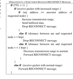
OPERATIONS IN A NODE WHICH RECEIVES RECONNECTMESSAGE
if (TTL > 1) {
if (receive packet with increased range) {
if (my address == ancestor address of requested node) {
Increase transmission range. Send buffered data.
Drop RECONNECT message. }
else if (distance between me and requested
node > 1 hop)
Drop RECONNECT message.
else if (distance between me and requested
node = = 1 hop) {
Decrease transmission range to normal. Forward RECONNECT message. }
}
else if (receive packet with normal range)
Forward RECONNECT message. }
B. Death of a Source Node
[image:3.595.58.255.148.370.2]When nodes send, receive or forward packets, they consume energy. There are some scenarios, shown in Fig. 2.a, which source shuts down because of shortage of energy. In ADMR, when node B becomes aware of a break, after sending REPAIR NOTIFICATION message to the nodes below itself, it sends request by RECONNECT message. But there is no source to reply to that request and the local repair will fail. So each receiver (R1,R2) tries to rejoin to the group explicitly by broadcasting MULTICAST SOLICITATION packet to the whole network. None of these receivers will receive any response from source (S) due to failure of source node. These transmissions cause an increase in overhead transmission and energy consumption. To avoid this, like Fig. 2.b, when node B becomes aware of break, before sending RECONNECT message, it monitors whether its parent node is the source of group. If so, it won’t send RECONNECT or REPAIR NOTIFICATION message. Instead, it makes its forwarding state in its tables expire and will notify the other nodes in the tree to make their states in their routing tables expire as well by the sending NOTIFICATION message.
[image:3.595.59.290.395.586.2]Fig. 2.a Break of the link S-B because of the shortage of the energy in node S
[image:3.595.336.528.612.657.2]TABLE II
OPERATIONS AT NODE B IN REPAIR MECHANISM
if (parent node == source of the group) {
Remove forwarding states in routing tables. Notify other nodes in the tree.
} else{
Send the REPAIR NOTIFICATION message to other nodes in the tree.
Send the RECONNECT message with the increased range.
}
C. Response to the RECONNECT Message by Source
In ADMR, when the source receives a RECONNECT packet, it responses with RECONNECT REPLY message to the requested node. But in FTADMR, when the source receives a RECONNECT message, it compares the next expected packet arrival time with the current time. If the next scheduled data packet is going to be sent soon, then the source replies with data packet to the requested node instead of sending RECONNECT REPLY message. The source sends data packet to the node it received RECONNECT message from. Otherwise it responds with RECONNECT REPLY message. This decreases the overhead on the network and causes the network becomes less prone to loss.
TABLE III
SOURCE REPLIES TO THE RECONNECTMESSAGE
if (the current time is close to the arrival time of next expected packet)
{
Wait until the arrival of next data packet. Send data packet to the requested node. }
else
Send the RECONNECT REPLY message to the requested node.
IV. SIMULATION AND RESULTS
In this section, we evaluate and compare the performance of FTADMR with ADMR. In section A, the metrics and methodology is described. And finally in section B, the simulation results are shown. The network is generated by randomly placing nodes in 100 m × 100 m squares. All of the nodes have a common structure and nodes are assumed static without any movements. The normal transmission range for nodes is 30 meters and number of nodes is varied from 50 to 100 in order to achieve different network densities in terms of mean numbers of neighbours. This is equivalent to increase the transmission range of nodes or decrease the simulation area. Nodes randomly selected as sources and receivers. Sources send 4 data packets per second. Each data packet is 64 bytes.
A. Metrics and Methodology
To assess the performance of FTADMR, we simulate these two protocols with NS2 and consider the following performance metrics:
• Packet Delivery Ratio (PDR) is a performance
metric which measures the fraction of the packets sent by all sources of groups that are received by all multicast receivers.
• Normalized packet overhead (NPO) is total
number of all data and control packets transmitted by any node in the network (either originated or forwarded), divided by total number of all data packets received across all multicast receivers. This metric represents the total packet overhead normalized by the successful results obtained in terms of data packets delivered [7].
• Control overhead is the number of control packet
transmitted (originated and forwarded) to the total number of data packets received by all receivers. This metric is used to show the amount of control packets that are transmitted for delivering each data packet.
• Delivery delay: is the average time it takes for a packet to travel from the source to the receiver. It shows the average amount of overhead that is involved in receiving a data packet.
• Energy Consumption is used to measure the
energy consumption. We use the energy model introduced in [13].
B. Simulation Result
Fig. 3 shows the packet delivery ratio of ADMR and FTADMR as a function of pause time in a scenario with 1 group, 4 sources and 5 receivers. It is shown that FTADMR performs better than ADMR and the difference in PDR becomes more prominent as the pause time increases. This is because that more nodes miss their energy as the time passes, and therefore the number of breaks increases and more repair mechanisms will be run. While ADMR creates more overhead, the load on network and battery consumption increase and make the network more prone to the loss.
Fig. 3. Packet Delivery Ratio: 1 Group, 4 Sources, 5 Receivers with Different Pause Times
[image:5.595.50.307.46.237.2]Fig. 4. Control Overhead: 1 Group, 4 Sources, 5 Receivers with Different Pause Times
[image:5.595.110.534.47.233.2]Fig. 5. Normalized Packet Overhead: 1 Group, 4 Sources, 5 Receivers with Different Pause Times
Fig. 6. Energy Consumption: 1 Group, 4 Sources, 5 Receivers with Different Pause Times
Fig. 7. Deliver Delay: 1 Group, 4 Sources, 5 Receivers with Different Pause Times
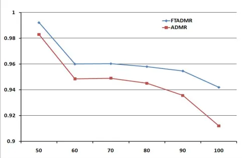
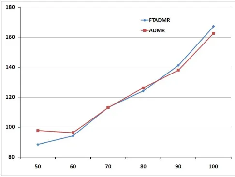
Two protocols are tested with different network densities in the setting of 1 group, 1 source and 5 receivers. The pause time for all simulated cases is 200 seconds. The results show that FTADMR performs better than ADMR in terms of PDR, NPO, control overhead and delivery delay. By increasing the number of nodes, more congestion will occur. So there is a decrease in PDR for both protocols. Moreover, when the traffic becomes higher, their nodes miss their energy sooner and more repair mechanisms will be run. Therefore the overhead increases as the network density increases.
[image:5.595.304.546.263.436.2] [image:5.595.46.291.282.471.2] [image:5.595.47.290.522.708.2] [image:5.595.305.546.613.770.2]Fig. 9. Control overhead: 1 Group, 1 Source, 5 Receivers with Different Network Density
Fig. 10. Normalized Packet Overhead: 1 Group, 1 Source, 5 Receivers with Different Network Density
Fig. 11. Energy Consumption: 1 Group, 1 Source, 5 Receivers with Different Network Density
Fig. 12. Delivery delay: 1 Group, 1 Source, 5 Receivers with Different Network Density
V. CONCLUSION
WSNs consist of many sensors which need robust and energy efficient routing protocols. Because of many advantages of ADMR, it is a good candidate protocol to be used for wireless Sensor Networks. In this paper we propose a mechanism in the repair procedure of ADMR to retrieve the lost packet. The ADMR protocol is improved to reduce overhead in these networks. The proposed protocol is able to reduce the overhead transmission, the normalized overhead packet, and delivery delay as well as increase the number of received packets.
REFERENCES
[1] “21 idea for 21st century”, business week, Aug. 30 1999, pp. 78-167.
[2] Al-Karaki, A. E. Ahmad, “Routing Techniques in Wireless Sensor Networks: A survey”, Wireless Communications, IEEE, Vol. 11, No. 6, 2004 pp. 6-28.
[3] A. Jamalipour, J. Zheng, “Wireless Sensor Networks, Networking perspective”, John Wiley, 2009, pp11.
[4] J. Sanchez, P. Ruiz, X. Liu, and I. Stojmenovic, “GMR:Geographic. Multicast Routing for Wireless Sensor Networks”, Proc. of IEEE,
2007.
[5] G. Zhao, X. Liu and A. Kumar, “Destination Clustering Geographic Multicast for Wireless Sensor Networks”, Proc. of IEEE, 2007. [6] G. Zhao, X. Liu, and A. Kumar, “Geographic Multicast with k-means
Clustering for Wireless Sensor Networks”, Proc. of IEEE, 2008. [7] J.G. Jetcheva, D.B. Johnson, “Adaptive Demand-Driven Multicast
Routing in Multi-Hop Wireless Ad Hoc Networks”, Proceedings of ACM MobiHoc’01, 2001.
[8] X. Hu, Y. Liu, M. Lee and T. Saadawi, ”route update and repair in wireless sensor network”, IEEE, 2004.
[9] Y. Liu, H. Zhu, K. Xu and W. Teng, “An Improved Route Repair Approach of Wireless Sensor Networks”, First International Multi-Symposiums on Computer and Computational Sciences, 2006, pp. 662-665.
[10] K. Kim, “A Resilient Multipath Routing Protocol for Wireless Sensor Networks”, Springer Berlin / Heidelberg, 2005, pp. 1122-1129.
[11] M. Pandey and D. Zappla, “A Scenario-Based Performance
Evaluation of Multicast Routing Protocols for Ad Hoc Networks”, IEEE International Symposium on World of Wireless, Mobile and Multimedia Networks (WoWMoM), Italy, 2005.
[12] A. Caruso, A. Urpi, S. Chessa, and S. De, “GPS-Free Coordinate Assignment and Routing in Wireless Sensor Networks”, Proc. IEEE Infocom, Vol. 1, USA, 2005, pp. 150-160.
[image:6.595.304.548.49.231.2] [image:6.595.47.289.282.466.2] [image:6.595.46.289.520.703.2]