Analysis and Design of Multistoried Building
With Shear Wall
K. Nagarathna1,Dr. B. Ramesh Babu2,G. Raghu Yadav3
M.Tech, Dept. of Civil Engineering, ALITS College, Affiliated to JNTUA, AP, India1
Principal, ALITS College, Affiliated to JNTUA, AP, India2
Dept. of Civil Engineering, ALITS College, Affiliated to JNTUA, AP, India3
ABSTRACT: In structural engineering, a shear wall is a wall composed of braced panels to counter the effects of lateral load like wind and seismic acting on a structure. Under several building codes including the International Building Code and Uniform Building Code all exterior wall lines in Wood or steel frame construction is braced. Plywood is the conventional material used in the Construction of shear walls, but with advances in technology and modern building methods, there are other prefabricated options which have made it possible to inject shear assemblies into narrow walls that fall at either side of an opening in a shear wall. Sheet steel and steel-backed Shear panels in the place of structural plywood in shear walls have proved to be far stronger in Seismic resistance. Walls have to resist the lateral force of the wind that tries to push the walls in and pull them away from the building. Shear walls are quick in construction, and in a country like India where shelter is very important in a short lapse of time shear walls can be built very quickly. The precision to which they are built is also very high compared to normally built brick structures. Hence the key objective of shear wall is to build a safe, tall, aesthetic building.
I. INTRODUCTION
Shear walls are vertical elements of the horizontal force resisting system. Shear walls are constructed to counter the effects of lateral load acting on a structure. In residential construction, shear walls are straight external walls that typically form a box which provides all of the lateral support for the building. When shear walls are designed and constructed properly, and they will have the strength and stiffness to resist the horizontal forces.
Now a day, shear walls are the most common structures built inside the structures in order to counteract severe earthquake forces. Earthquake is a major concern for the engineers to give stability to the buildings. Properly designed and detailed buildings with shear walls have shown very good performance in past earthquakes. Shear walls must provide the necessary lateral strength to resist horizontal earthquake forces. When shear walls are strong enough, they will transfer these horizontal forces to the next element in the load path below them. These other components in the load path may be other shear walls, floors, foundation walls, slabs or footings.
II. LITERATURE REVIEW
Varian U.H et al (2002) described about shear walled buildings under horizontal loads. Considering in his design “Reinforced concrete framed buildings are adequate for resisting both the vertical and the horizontal loads acting on shear walls of a building”. In his 2nd edition 2002 of “Design of structures”. He gave rigidity of shear wall, tensional rigidity and shear center of a building in detailed description.
Jadhav.A.P et al Associate Professor Rajarambapu Institute of technology rajaramnagar, Illampu has given a detailed report on the form work used for the construction of shear walls. Mr.A.P.Jadhav highlighted the importance of quickness in construction and the need for earthquake resistant building for better sustainability of life.
III. STUDY METHODOLOGY
Function of shear wall
Shear walls must provide the necessary lateral strength to resist horizontal earthquake forces. When shear walls are strong enough, they will transfer these horizontal forces to the next element in the load path below them. These other components in the load path may be other shear walls, floors, foundation walls, slabs or footings. Shear walls also provide lateral stiffness to prevent the roof or floor above from excessive sideway. When shear walls are stiff enough, they will prevent floor and roof framing members from moving off their supports. Also, buildings that are sufficiently stiff will usually suffer less nonstructural damage
Forces on shear wall
Shear walls resist two types of forces: shear forces and uplift forces. Shear forces are generated. In stationary buildings by accelerations resulting from ground movement and by external forces Like wind and waves. This action creates shear forces throughout the height of the wall between the top and bottom shear wall connections. Uplift forces exist on shear walls because the horizontal forces are applied to the top of the wall. These uplift forces try to lift up one end of the wall and push the other end down. In some cases, the uplift force is large enough to tip the wall over. Uplift forces are greater on tall short walls and less on low long walls. Bearing walls have less uplift than non-bearing walls because gravity Loads on shear walls help them resist uplift. Shear walls need hold down devices at each end when the gravity loads cannot resist all of the uplift. The hold down device then provides the Necessary uplift resistance.
Shear walls should be located on each level of the structure including the crawl space. To form
An effective box structure, equal length shear walls should be placed symmetrically on all four exterior walls of the building. Shear walls should be added to the building interior when the exterior walls cannot provide sufficient strength and stiffness. Shear walls are most efficient when they are aligned vertically and are supported on foundation Walls or footings. When exterior shear walls do not provide sufficient strength, other parts of the Building will need additional strengthening. Consider the common case of an interior wall supported by a sub floor over a crawl space and there is no continuous footing beneath the wall.
For this wall to be used as shear wall, the sub floor and its connections will have to be Strength need near the wall. For Retrofit work, existing floor construction is not easily changed. That’s the reason why most retrofit work uses walls with continuous footings underneath them as Shear walls.
Classification of shear walls
Simple rectangular types and flanged walls (bar bell type)
Coupled shear walls
Rigid frame shear walls
Framed walls with in filled frames
Column supported shear walls
Core type shear walls
Types of shear walls
IV. ANALYSIS AND RESULTS
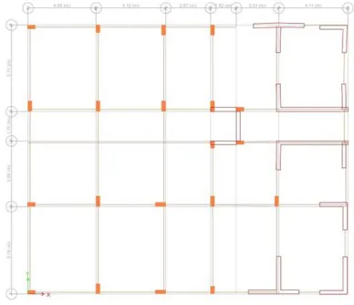
Building plan with shear wall
Fig 1: view of Building plan with shear wall
Shear Wall Design
GIVEN,
Length of shear wall = 4.16m Thickness of shear wall = 250mm Assume,
Fck = 25
Fy = 415 N/mm2
STEP1:
Determine design loads
Note: load factor 0.8 for instead of IS value 1.2 for gravity loads P1 = 0.8 * 1950 + (1.2 * 250 ) = 1860
P2 = 1.2 ( 1950 + 250 ) = 2640 Moment = 1.2 ( 600 + 4800 ) = 6840 KNm Shear = 1.2 ( 20 + 700 ) = 864 KN.
STEP2:
Check whether boundary elements are required
NOTE: ( extreme stress are more than 0.2 Fck ) = 0.2 x 2.5 = 5 N /mm2 Fc = P/A + M/I * Y
I = BD3/12 = 4160 * 2503/12 = 1.5 * 1012 mm4
A = b d = 4160 * 250 = 1.04 * 106 mm2 F/y = M/I
I = M/I * Y ( normal stress + permeable stress ) Fc = 11.52 , -6.45
Boundary elements are required
STEP 3 :
Bar bells type 3400 + 2 ( 380 ) = 4160 mm
STEP 4 :
Check two layer steel IS required
a) Shear stress is more than 0.25√Fck
b) The thickness of section is more than 200mm
Depth = 3780mm V = Vu/bd
= 864 * 103 / 250 * 3780 = 0.9
0.25√20 = 1.11 N/mm2
Thickness is 250 more than 200mm so two layer is required
STEP 5 :
Design steel is required
Minimum steel is 0.0025 ( 0.25 % ) Assume for 1 m
= 0.0025 * 250 * 1000 = 625mm2 = two layers Provide T 10 @ 250 Πd2/4 = Π*102/4 =314mm2 For one layer If ,
Two layer = 628mm2 Required = 625mm2 Provided = 628mm2
STEP 6 :
Calculate Vs taken by steel
V = 0.92 N/mm2 Vs = Vu-Vc
Vc = Vu – Tc * d So,
Vs = ( 0.92 – 0.36 ) * 250 * 3780 τcFol 0.25 % steel and Fck = 20 = 0.36 N/mm2 Vs = 529.2 KN
STEP 7 :
Calculate steel necessary to take Vs
Vs/d = 0.87 fy A*Sv/Sv
Asv/sv = 529.2 * 103 / 0.87 *415 * 3720 = 0.388
Consider 1m in height = Sv
Asv = 628mm2( for layer ) Asv / Sv = 628/1000
= 0.628mm2 Flexural strength 1 web parts
= 1107KN
STEP 8: x/l& ẋ/l
x/l = ƛ+ɸ/0.36 +2ɸ ƛ = Pw/ Fck + l
= 1107*103/20*250*5400 = 0.065
Like = ɸ = 0.87 fy/ fck = 0.045
β = 0.516 for 415 grade x/l = 0.24
ẋ/l = 0.5 for 415 x/l ˂ ẋ/l
mu/fck*fl2 = ɸ ( 1+ ƛ/ɸ ) ( 0.52 – 0.42 * 0.20 ) = 0.041
Mu = 0.04*20*250*34002 Mu = 2370KNm
STEP 9 :
Moment from BE = 6480 – 2370 = 4110 KNm
STEP 10:
C & T in BE = 3400 + 380 = 3780mm = 3.78m
Axial loads = mi/c = 4110/3.86 = 1065KN
STEP 11:
Calculation compression at one end and tension at another end
Extraction area = 0.2025 In compression
P2 = (0.2025*2640 ) = 535
In tension
= 0.2025*1860 = 377 KN
Compression end = 1065 + 535 = 1600 KN Tension end = -1065 + 377 = -688 KN
STEP 12 :
Reinforcement around opening site as 1200*1200
Area of reinforcement cut off by the opening = 1200*t*0.0025
= 1200*250*0.0025 = 750mm2
V. CONCLUSION
Thus shear walls are one of the most effective building elements in resisting lateral forces during Earthquake. By constructing shear walls damages due to effect of lateral forces due to earthquake and high winds can be minimized. Shear walls construction will provide larger stiffness to the buildings there by reducing the damage to structure and its contents. Not only has its strength, in order to accommodate huge number of population in a small area tall structured with shear walls are considered to be most useful. Hence for a developing nation like India shear wall construction is considered to be a back bone for construction industry.
REFERENCES
(1) U.H. Varanasi in his second edition of “Design of structures” S.K. Duggal in his “Earth quake resistant design of structures” Page no: 301, 8.12 about Shear Walls.
(2) S.K. Duggal in his “Earth quake resistant design of structures “pg.no:305 on flexural strength 8.14.1 Case: 1, case: 2. S.K. Duggal in his “Earth quake resistant design of structures” 8.16 Design of Shear walls Which is also given in is code 13920:1993
(3) Mr A.P. Jadhav Associate Professor Rajarambapu Institute of technology rajaramnagar, Illampu Has given a detailed report on the form work used for the construction of shear walls.
(4) A report on effects of openings in shear walls on seismic response of structure by sharminriza chowdhary, department of civil engineering dhake-1208, Bangladesh mostly focused On the design of shear walls with openings on seismic response using E- Tabs
(5) I.S 456:2000. As per clause 32, design for wall describes, design of horizontal shear in clause 32.4 given Details of how shear wall have to be constructed.
(6) I.S:1893 Criteria of Earth Quake resistant Buildings Part (3) page 23, clause 4.2 gives the Estimation of earth quake loads.