Themed Section: Science and Technology
A Study on Controlling the Renewable Power System by
utilizing the Microgrid
Sumalatha Kalakotla
Assistant Professor, Department of Electrical and Electronics Engineering, University College of Engineering, Kakatiya University, Kottagudem, India
ABSTRACT
As of late the control of microgrid has been the focal point of broad research because of its adaptability to adequately use the smaller scale sources while guaranteeing dependability. The microgrid innovation is one of the current advancements in the territory of electric power systems that guide the utilization of non-conventional energy sources in parallel with the non-conventional energy sources. Checking and control of microgrid is basic for its proficient and viable working. The work exhibited in this paper is centered around the outline, control and advancement of synchronization between non-conventional energy sources (photovoltaic panel) and conventional energy sources (battery) to fulfill the power demand of the matrix by utilizing WSN ( remote sensor systems) innovation. The target of this paper is to propose a model to think about the execution examination of power observing between photovoltaic panel and battery by sensing parameters like generated power, accessibility of power hold and so forth through WSN (ZigBee). The key simulation and experimental results are incorporated to confirm the best possible task and control of microgrid.
Keywords: Photovoltaic panel, boost converter, DC-AC converter, conventional energy source ZigBee, relay, synchronization, PWM technique, microcontroller.
I.
INTRODUCTION
Pollution concerns, expanding power demand and increasing expense of fossil fuel has occupied humanity's consideration towards renewable energy. Power being a basic need, its dependability and supportability is a noteworthy focal point of research. Micro matrix is another promising zone of energy sector for neighborhood energy age utilizing renewable energy sources, for example, PV, wind, fuel cell, micro hydro, biomass, and so forth., which calms the weight on conventional generators and transmission lines. Different power circuit designs in micro matrix guarantee to build the Reliability of power supply if outfitted with complex and reasonable control procedures, for example, power
sharing plans for PV sources in different operating modes.
More than 60 nations around the globe have set focuses for renewable energy supply. The kinds of renewable energy incorporate solar, wind, hydrogen, biomass, geothermal, hydropower, and biodiesel. A considerable lot of these renewable energy sources are intended to supply energy into the electric power system. Photovoltaic enable the customers to produce power in a perfect, solid and calm way. Photovoltaic cells join to shape photovoltaic system.
mountings and associations for the other parts. A little PV system can give energy to a solitary customer, or to confined gadgets like a light or a weather gadget. Huge framework associated PV systems can give the energy expected to serve numerous clients. A solitary individual solar cell has a low voltage (typically 0.5V). Consequently, a few cells are wired together in arrangement offering ascend to a "cover". The overlay is then amassed into a defensive weatherproof packaging, along these lines making a photovoltaic module or a solar panel. Modules might be then hung together to frame a photovoltaic cluster. The power generated can either be put away, put into coordinate utilize (island/standalone plant), encouraged into a major power network powered basically by focal age plants (lattice associated/framework tied plant), or sustained into a little matrix in the wake of consolidating with one or numerous household power generators (half breed plant). Contingent upon the application write, whatever is left of the system known as adjust of system or "BOS" comprises of a few segments. The BOS is reliant on the heap profile and the sort of system. PV energy change systems can either be off-matrix (stand-alone) or framework associated. A portrayal of the two kinds of PV systems takes after.
1) Off-Grid PV Energy Systems:
The off-grid PV systems are typically utilized as a part of country or remote territories, where the grid isn't accessible or not accessible. The off-grid systems can be further partitioned into two sub-classifications: household and non-residential applications. In the previous, the PV system is utilized to give power to little groups, where association with the power grid isn't practical. Normally little PV systems (< 5kW) are utilized for family applications together with an energy stockpiling unit and a backup system. In the last mentioned, the PV system is utilized to invigorate a
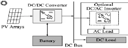
solitary mechanical or horticultural load that isn't associated with the grid, for example, a water pump, movement light, or media transmission gear. A battery unit is utilized to store energy. An off-grid PV energy system comprises of a solar cluster associated with a DC/DC converter, a battery bank and a discretionary DC/AC inverter as appeared in Figure 2.
Figure 1. Off-grid PV energy conversion system.
2) Grid-Connected PV System:
Grid-associated PV systems are typically made out of three segments: a PV cluster, a DC/DC converter and a DC/AC inverter as showed in Figure 1.3. Grid-associated PV systems are likewise classified into two fundamental gatherings: distributed grid associated applications and brought together grid-associated applications. In distributed applications the PV system is mounted on the premises of a client who is associated with the grid. The PV system can be associated with the heap side of a power meter, and the energy generated is utilized by the client stack. Any energy surplus can be conveyed to the grid or the other way around. This strategy is called Net Metering. Another technique to consider is the PV energy system as a distributed generator (DG), which is associated straightforwardly to the grid with a different meter.
Keeping in mind the end goal to take care of the electricity demand of the grid consistently we have to utilize the conventional energy source for instance battery in parallel with the photovoltaic panel as a result of the inaccessibility of daylight amid evening times and changes in climatic conditions. The power supply either from the photovoltaic panel is from the battery happens by exchanging. This exchanging needs entire synchronism between photovoltaic panel and battery. A financial and dependable correspondence backbone alongside accurate observing system is fundamental. Checking of the power system basically has two primary modules: correspondence module which is the backbone and sensor module for sensing the diverse parameters like voltage, current and power. As of late, WSNs have been perceived as a promising innovation that can improve different parts of the present electric power systems, including age, conveyance and usage, making them an indispensable segment of cutting edge electric power systems, microgrids. ZigBee based WSN are turned out to be more dependable in packet conveyance because of work based multi-jump organizing. In India setting of use of WSNs to power systems, new thoughts and usage designs are coming up. The work displayed in this paper is centered around the plan, control and advancement of synchronization between non-conventional energy sources (photovoltaic panel) and conventional energy sources (battery) to fulfill the power demand of the grid by utilizing WSN ( remote sensor systems) innovation. The goal of this paper is to propose a model to consider the execution examination of power checking between photovoltaic panel and battery by sensing parameters like generated power, accessibility of power hold and so forth through WSN (ZigBee). The key simulation and experimental results are incorporated to check the correct task and control of microgrid.
II.
LITERATURE SURVEY
Smart grid technology is one of the current advancements in the area of electric power systems that guide the utilization of non-conventional sources of energy in parallel with the conventional sources of energy. Monitoring and control of smart grids is fundamental for its efficient and effective functioning. In this paper, we propose architecture for monitoring power in smart grid applications utilizing WSN technology. A model power sensing module is planned and created to figure the power for any sort of burdens. Utilizing WSN technology, the observed power is conveyed to the sink at intermittent interims. Multi bounce remote work network is set up utilizing IRIS notes to upgrade the correspondence between the power sensing hubs and the sink. The information gathered is a rich source of store for information investigation and demonstrating. Various smart actions and applications, for example, power theft recognition, energy efficient building configuration, smart robotization systems and smart metering can advance out of the proposed demonstrate. A novel power theft location calculation is proposed and reenacted in this paper.
is given. The effectiveness of the proposed control plot is examined with a research facility model of the micro grid with various leveled control bolstered by sources like Solar PV, Wind, hydro turbine driven synchronous machine and Fuel cell based renewable energy sources. The micro grid has the capacity of reconfigurable control. The Local Source Controllers (LSC) is connected with Controller Area Network (CAN) for quick information exchange and RS-485 for mass information exchange. Battery stockpiling is accommodated delayed energy back up and ultra-capacitor for transient and fleeting power bolster amid dynamic stage. The PV interface of this micro grid is explored under different conditions, for example, substantial variety in its radiation level, greatest power point tracking, concentrated control for active power, arrange active and reactive power control with de-incorporated task, progressive control usefulness of PV source with other micro grid sources and so on. The discontinuous idea of photovoltaic source causes an impossible to miss impact on the micro grid task. This and other imperative perceptions are dissected for further examination and examinations concerning the control parts of PV sources in a micro grid paradigm. The key simulation and experimental results are incorporated to confirm legitimate activity and control of the micro grid.
III. BASIC CIRCUIT DIAGRAM
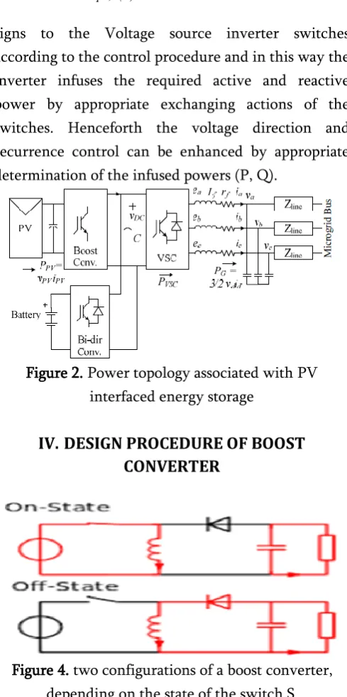
The PV source should supply energy utilizing power converter controlled for both active and reactive power and manage the transport voltages at whatever point required. Fig.3.1 demonstrates the square chart portrayal of a power converter related with a PV source in a microgrid. The course of action is additionally bolstered by energy stockpiling of battery. The immediate terminal voltages, DC transport voltage, stack streams and infused ebbs and flows by the VSC are estimated and encouraged into the VSC control circuit. The control circuit gives fitting door
signs to the Voltage source inverter switches according to the control procedure and in this way the inverter infuses the required active and reactive power by appropriate exchanging actions of the switches. Henceforth the voltage direction and recurrence control can be enhanced by appropriate determination of the infused powers (P, Q).
Figure 2. Power topology associated with PV interfaced energy storage
IV. DESIGN PROCEDURE OF BOOST
CONVERTER
Figure 4. two configurations of a boost converter, depending on the state of the switch S.
The fundamental standard of a Boost converter comprises of 2 unmistakable states (see figure 8):
In the On-express, the switch S (see figure 6) is shut, bringing about an expansion in the inductor current;
The input current is the same as the inductor present as can be found in figure 7. So it isn't broken as in the buck converter and the prerequisites on the information channel are casual contrasted with a buck converter.
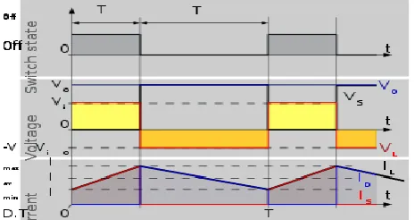
Figure 5: Waveforms of current and voltage in a boost converter operating in continuous mode.
At the point when a boost converter works in nonstop mode, the current through the inductor never tumbles to zero. Figure 9 demonstrates the common waveforms of streams and voltages in a converter operating in this mode. The yield voltage can be figured as takes after, on account of a perfect converter (i.e. utilizing segments with a perfect conduct) operating in enduring conditions:
During the On-state, the switch S is closed, which makes the input voltage ( ) appear across the inductor, which causes a change in current ( ) coursing through the inductor during the time period (t) by the equation:
Toward the finish of On-state, the increase of IL is
therefore:
D is the duty cycle. It represents the fraction of the commutation period T during which the switch is On. Hence D varies in between 0 (S is never on) and 1 (S is always on).
During the Off-state, the switch S is open, so the inductor current flows through the load, the evolution of IL is:
Therefore, the variation of IL during the Off-period is:
As we consider that the converter operates in steady-state conditions, the amount of energy stored in each of its components has to be the same at the beginning and at the end of a commutation cycle. In particular, the energy
stored in the inductor is given by:
So, the inductor current has to be the same at the start and end of the commutation cycle. This means the overall change in the current (the sum of the changes) is zero:
Substituting and by their expressions yields:
This can be written as:
Which in turn reveals the duty cycle to be?
V.
BLOCK DIAGRAM AND WORKING
Figure 6. block diagram of the prototype
The figure 6 demonstrates the schematic diagram portrayal of control of microgrid. It principally includes photovoltaic panel as non conventional energy source, DC-DC boost converter, inverter, 8-bit 80C51 5V microcontroller, ZigBee, DPDT relay, stack. The course of action additionally comprises of battery which acts as a conventional energy source.
At the point when daylight falls on the photovoltaic panel, these utilizations light energy from the sun to create electricity through photovoltaic impact so we get DC voltage. The voltage which is accessible from the solar exhibit is variable and less. Keeping in mind the end goal to acquire consistent voltage DC-DC converter is utilized. The voltage generated by the exhibit is less it can be expanded by interfacing it with boost converter which impressively ventures up the yield voltage which could take care of the demand of power. The yield of the converter is nourished to inverter1 which creates AC voltage. The Pic 8-bit microcontroller is utilized for terminating beat age. It has inbuilt PWM and A/D converters. The microcontroller is modified to produce the terminating beats with settled obligation cycle utilizing PWM technique. The game plan likewise comprises of Arduino board it comprises of 14 computerized input/yield pins. The IGBT beat pin is associated with pin - 11, yield of the boost converter is associated with pin AO (simple contribution) of the Arduino board. The pin 13 of board acts as a flip switch pin. The game plan
likewise comprises of DPDT relay acts as a basic leadership gadget that recognizes irregular or blame conditions and start insurance actions. It is associated with inverter1, inverter 2 and stack. On the other side the battery utilized as conventional energy source which associated with the inverter 2.
On the off chance that the voltage inside the reference esteems, the flip switch pin will turn out to be high and it is detected by the ZigBee1 and bulb will glow from the yield of solar panel, if the voltage beneath the reference esteems, the flip switch pin will turn out to be low and it is detected by the ZigBee2 and bulb will glow from the battery. There ought to be appropriate synchronization for the control and activity of microgrid. It is checked both by simulation and experimentally with a research facility model of info 12V and yield 230V appeared in underneath figure 7 and CRO yield of frequency 32 kHz is appeared in figure 8.
Figure 7. laboratory prototype
VI. SIMULATION CIRCUIT DIAGRAM AND
RESULTS
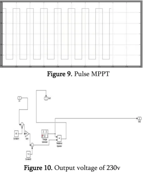
Figure 9. Pulse MPPT
Figure 10. Output voltage of 230v
VII.
CONCLUSION
A complete system for the remote monitoring and control of PV plants has been exhibited and its capacities have been examined and tried. The utilization of the WSN expands the effectiveness of the system autonomously of where the plants are placed, even a long way from the electrical circulation network and from the traditional and wired telecommunication systems. Because of the minimal effort and diffusion of the WSN devices, the transmission system is genuinely shoddy and it is relied upon to wind up less expensive and less expensive. In the meantime, we are associated with expanding the marvels that can be remotely observed and controlled, particularly if identified with the power generation in light of renewable sources. In this paper, architecture for power monitoring system utilizing the WSN technology is proposed. A model for power sharing amongst conventional and non conventional sources is created. It is obvious from the experimentations that the WSN might be effectively utilized to microgrid for monitoring and controlling purpose.
VIII.
REFERENCES
[1].H. Nikkhajoei and H. Robert, "Conveyed Generation Interface to the CERTS Microgrid", IEEE Transactions on Power Delivery, vol.24, no. 3, pp. 1598-1608, July 2009.
[2].Rupesh G. Wandhare, Sushil Thale, Vivek Agarwal "Outline of a photovoltaic power molding framework for various leveled control of microgrid" IEEE exchange on control framework 2014.
[3].E. Rikos, S. Tselepis, C. Hoyer-Klick and M. Schroedter-Homscheidt, "Dependability and Power Quality issues in Microgrids Under Weather Disturbances ", IEEE Journal of chose subjects in connected earth perception and remote detecting, vol. 1, no. 3,pp. 170-179,Sep. 2008. [4].S. Thale and V. Agarwal "Plan and
Implementation of Communication and Control Architecture for Solar PV Based Microgrid Supported by PEM Fuel Cell Based Auxiliary Source" in 37th IEEE Photovoltaic Specialist Conference 2011, Seattle, WA, June 2011.
[5].C. Sao and P. Lehn, "Control and Power Management of Converter Fed Microgrids" IEEE Transactions on Power System, vol.23, no.3, pp.1088-1098, Aug. 2008.