© 2017 IJSRST | Volume 3 | Issue 8 | Print ISSN: 2395-6011 | Online ISSN: 2395-602X Themed Section: Science and Technology
Fuzzy based Controller for rectifiers of a Direct-Drive Permanent-Magnet
Wind Power Generator
P. Kaseem
1, M. Ramasekhara Reddy
2 1PG Scholar, Power and Industrial Drives, Dept. of EEE, JNTUA college of Engg., Ananthapuramu, Andhra Pradesh, India 2
Assistant Professor, Dept. of EEE, JNTUA College of Engg., Ananthapuramu, Andhra Pradesh, India
ABSTRACT
This paper proposes a detailed control strategy for multiple parallel connected converter units integrated with wind turbine driving PMSG. A model of multiple rectifiers in parallel with common dc link and zero sequence current dynamics are derived and analyzed. The structure of parallel back to back pulse width modulation converters are adopted for multi megawatt high power generation system. The fuzzy based controller is developed to restrain circulating currents flows between the power modules caused by power device discrepancy and asynchronous operation of the parallel units. The control driving signals are generated by individual current control and produced by carrier phase shifting synchronously. The effectiveness of the proposed control strategy is verified through MATLAB simulations.
Keywords: PMSG, Zero sequence current, parallel operating controllers, Fuzzy logic controller
I.
INTRODUCTION
Wind is one of the most abundant renewable sources of energy in nature. Wind energy can be harnessed by a wind energy conversion system (WECS) [4]-[5] composed of a wind turbine, an electric generator, a power electronic converter and the corresponding control system. Based on the types of components used, different WECS structures can be realized to convert the wind energy at varying wind speeds to electric power at the grid frequency. The most advanced generator type is perhaps the permanent magnet synchronous generator (PMSG). This machine offers, compared at the same power level and machine size, the best efficiency among all types of machines with high robustness and easy maintenance due to slip ring‐less and exciter‐less features. The inherent benefit of permanent magnet which supplies rotor flux in synchronous machines without excitation loss supports the wind power generation development. This thus results in the increasing use of PMSG [3].
The rectifiers in parallel connected to the PMSG have the advantage of higher reliability, high efficiency, and lower grid side harmonics The parallel configurations [2]–[9] can be classified as parallel voltage source converters(VSC) with separate direct voltage links and parallel VS converters(VSC) with a common direct
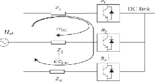
As shown in Figure 1, The structure of parallel back to back PWM converters is adopted for multi megawatt high-power generation system
Figure 1. High-power direct-drive variable-speed PMSG wind generator system connected to the power
grid.
Figure 2. Multiple three-phase PWM rectifiers with parallel connection.
This model provides separate control of the generator side converter and grid-side converter. The interconnection of the power converters in this manner can accommodate not only multiphase but also three phase generators for WTs. In this paper, zero-sequence circulation mathematical model is derived and analyzed. An improved space vector SVPWM parallel control strategy is presented to repress the zero-sequence circulating current. Independent current regulation is implemented for each branch power module.
II.
CIRCULATING CURRENT
CONTROLLER
The term circulating current has been generally used to depict streams that stream among the converter units in parallel [1]. In rehearse; a circling current is thought to be a present that goes amiss from the sought burden current level just as shared by the paralleled units.
A. Expression of the Circulating Current at Generator Side
Figure 2 shows n rectifiers in parallel; all the active switches are assumed to be ideal switches, and the
equivalent series resistances of inductors are also considered.
Figure 3. Circulating current among multi converters.
Applying Kirchhoff’s voltage law, the following equations can be obtained corresponding to a-phase, respectively:
(1)
is the voltage between the negative end of and neutral point. Where Zj = d/dt + Rj,jϵ{1, 2, . . . , n}, the general phase current expression for any individual branch unit in parallel connection.
⁄ ⁄ (2)
Where k ϵ {a, b, c}; is the k-phase line current of the jth converter, is the source voltage. The circulating currents for n paralleled three-phase converters in Figure 3 can be defined as follows. Considering the circulating current for the first branch unit B1 as displayed in the Figure 3, denotesthe circulating current between
B1 and B2. denotes the circulating current between B1 and B3. Similarly, the circulating current between B1 and Bn is denoted as CCk1n. Therefore, the
k-phase circulating current of the first converter CCk1 consists of n circulating-current components as follows: (3)
The expression for the k-phase circulating current of the
jth converter can be derived [9] as follows
∑ ⁄ (4)
∑ [ ( )]
(5)
It is shows that both the output dc voltage and the three ac phase voltages contribute to the generation of the circulating currents. The impedance of the kth converter in a particular circulating path also influences the magnitude of its circulating current.
B. Circulating-Current Model of Three-Phase Parallel Converters in abc Coordinate
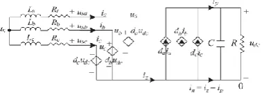
A phase-leg-averaged model for a single two-level three phase rectifier is shown in Figure 4 [8].
Figure 4. Phase-leg-averaged model of a single two-level three-phase rectifier.
Applying Kirchhoff’s voltage law and the current law to node n ( at ) results in a set of differential and algebraic equations
(6) The system equation can be written as
[
]
[
] [
] [ ]
[
] [ ] (7)
Applying Kirchhoff's voltage law to loops that are formed among the converters results in 3n − 1 algebraic equations
(8)
Where k ϵ (a, b, c) and Rs and Ls are the equivalent resistance and inductance of the PMSG, respectively ia = ia1 + ia2 + . . . + ian
ib = ib1 + ib2 + . . . + ibn
ic = ic1 + ic2 + . . . + icn
Applying Kirchhoff’s current law to node n (at ) results in one algebraic equation
(9) Differentiating (9), we get,
(10) Assuming = = · · · = Ln and = = · · · = Further arranges the set of equations as the state-space form
̇
(11)
Where
]T Is the State vector
U= [ , , , , , , . . . . , , , ]T I is the input vector. Y is the output vector. The state matrix is
A= [
]
[
]
And the input matrix is
B= [
] [
]
The output matrix C is the identity matrix with the dimensions of 3n × 3n
T =
[ ]
I is the identity matrix with the dimensions of 3× 3. The transfer function matrix is calculated in the Laplace domain based on the state-space model.
G(s) = C(sI-A)-1B
= [ ] [
] (12)
Where the first terms represent the circulating-current part and the second terms represent the currents that flow from the PMSG to the converters
C. Model of Three-Phase Parallel Converters in d−q−0 Rotating Coordinate
Assuming that the voltage udc and current are continuous and with small ripples, the phase voltage expression is ukj = dkjudc. Compared with the inductance, the resistance of each power module is small. Neglecting resistance, the state-space equations for the two converters in parallel connection are
[ ] [ ] [ ] [ ] [ ] [ ] [ ] [ ] (13) [ ] [ ] (14)
By transforming (13) and (14) from the stationary reference frame into the synchronous d−q−0 rotating reference frame [6]
[ ] [ ] [ ] [ ] [ ] [
] (15)
[ ] [ ] [ ] [ ] [ ] [
] (16)
[ ] [ ] [ ] [ ] (17)
Where ω is the ac line frequency. ud−uq−u0 is the d−q−0 axis components of the ac voltage in the d−q−0 reference frame, respectively. id1−iq1−i01 and id2−iq2−i02
are the d−q−0 components for the first converter and second converter, respectively. dd1−dq1−d01 and dd2−dq2−d02 are the d−q−0 components of the duty
cycles for the first converter and second converter, respectively.
u0 = usa+ usb+ uscand d0 = da +db + dc. The equivalent
circuit of three-phase parallel rectifiers in the d−q−0 rotating reference frame is shown in Figure 5. It is noted that a zero-sequence current occurs in the 0-axis and plays a significant role in the paralleled multiple rectifiers.
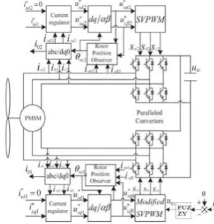
D. Zero-Sequence Current Control Scheme
Figure 6. Shows the designed control scheme for zero sequence dynamics developed according to the equivalent circuits of three phase parallel Converters in d-q-o rotating reference frame.
.
Figure 5. Equivalent circuit of three-phase parallel rectifiers in d−q−0 rotating Reference frame.
A modified SVPWM control strategy is proposed for parallel converters. Individual branch unit uses a separate current regulator. The controlling algorithm can be summarized as follows: First, the zero sequence current is suppressed by using a fuzzy controller on the 0-axis which produces the output zero-sequence voltage . The reference voltage vectors and are transformed into the stator coordinate by coordinate transformation, according to the sector in which the reference vector stays by using SVPWM modulation, and duty cycles are calculated. Second, the zero sequence output voltage is normalized and superposed with modulation duty cycles. Finally, the resulting duty cycle will be compared with the modulating carrier wave, and the switching function is obtained.
From the Figure 5, the two parallel rectifiers contain a zero sequence current path in d−q−0 reference frame due to the discrepancy of 0-axis duty cycle components. From (15) and (16), the dynamics of zero-sequence current are expressed the second term on the right can be expected as a disturbance.
The fuzzy controller can be cascaded with the plant to achieve closed-loop current regulation. The bandwidth of the control can be designed to be high, and a strong current regulation that suppresses the zero sequence current can be achieved. For n number of rectifiers in parallel, the sum of zero sequence currents is equal to zero, i.e., + + · · · + = 0. Due to the interaction among the n currents, the number of independent zero-sequence currents is n − 1. The number of zero sequence current controllers should be n − 1 for n parallel rectifiers.
III.
FUZZY LOGIC CONTROLLER
Fuzzy logic controller, approaching the human reasoning that makes use of the tolerance, uncertainty, imprecision and fuzziness in the decision making process and manage to propose a very satisfactory operation, without the need of a detailed mathematical model of the system, just by integrating the expert’s knowledge into fuzzy rules. In addition, it has essential abilities to deal with noisy date or inaccurate, thus it has able to develop control capability even to those operating conditions where linear control techniques fails i.e., large parameters variations.
Rule Base: It consists of a number of If-Then rules. Then side of rules is called the consequence and If side
is called antecedent. These rules are very similar to the human thoughts and then the computer uses the linguistic variables. Rule base of FLC is listed in table 1
Table 1. MEMBRSHIP FUNCTI0N TABLE
FUZZY RULES
E(n)
NB NS ZE PS PB
NB NS ZE PS PB
ZE PB PB PS PS
PS PS PS ZE ZE
PS ZE ZE ZE NS
ZE ZE NS NS NS
NS NS NB NB ZE
IV.
CONTROL OF PMSG WITH MULTIPLE
RECTIFIERS
In wind turbine PMSG systems, three system variables need to be strictly controlled [6]: (1) the optimal power generated by the PMSG at different wind speed levels; (2) the active and reactive power injected into the grid; (3) the DC bus voltage of the back to back converter. The proposed system contains a direct-drive wind turbine PMSG fed by a back-to-back converter. The use of parallel converters compared with a solution with only one converter is higher reliability, higher efficiency, and the possibility of extremely low grid harmonics.
In parallel connection, one converter unit functions as a master and the others function as slaves. A serial communication bus is arranged between the converter units in which each unit has its own modulation cycle counter and it is synchronized with each other on the basis of serial communication messages. In this manner, the modulation counters operate as simultaneously as possible.
Carrier phase-shifting modulation technique [10] has a great advantage for power converters in parallel. When a module fails to operate, the master controller just changes the corresponding carrier phase angle and limits the capacity of the system, other modules can continue to work, standby unit can also be activated, and full-power operation can still be achieved. The PMSG is controlled by two 750-kW generator-side converters connected in parallel in a rotor rotating d−q axis frame, with the d-axis oriented along the rotor-flux vector position. In this way, the d-axis current is held to zero to obtain maximum electromagnetic torque with minimum current. The optimum active power setting or torque reference can be calculated according to maximum power point tracking strategies. The two sets of PWM driving signals are generated by using separate current regulators and produced by
carrier phase-shifting synchronously. The rotor position is fed by the rotor position observer without any position sensor. Each converter module is independent of each other identifying the rotor flux position. The currents of each module are balanced and synchronized with respect to each other producing the optimal total generator torque. This arrangement will reduce the requirements for large impedance needed to equalize the current sharing and allow increasing the power handling capability for a converter with parallel connection. The zero-sequence current fuzzy controllers have been integrated with the control of parallel converters.
V.
SIMULATION RESULTS
Figure 8.Ten kilowatt generator side circulating current with PI controller
Figure 9. Ten kilowatt grid side circulating current with PI controller
Figure 10.Generator currents of individual converter when generator operated at 1.5KW with PI
controller.
Figure 11. Three phase Generator currents of individual converter when generator operated at 1.5KW with PI
controller.
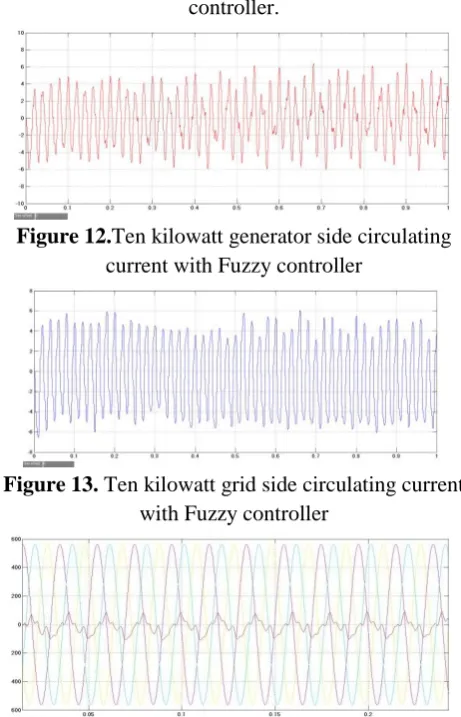
Figure 12.Ten kilowatt generator side circulating current with Fuzzy controller
Figure 13. Ten kilowatt grid side circulating current with Fuzzy controller
Figure 14. Three phase Generator currents of individual converter when generator operated at 1.5KW with Fuzzy
Figure 15. Generator currents of individual converter when generator operated at 1.5KW with Fuzzy
controller
OBSERVATION TABLE
Circulating currents
Total harmonic distortion (THD) With PI
controller
Fuzzy Logic Controller
Generator(10KW)side circulating current
29.20% 17.52%
Grid side circulating current
33.14% 28.16%
Generator(1.5MW) currents of
individual converter 35.86% 25.26%
Three Phase Generator(1.5MW)
currents of individual converter 34.13% 20.20%
VI.
CONCLUSION
This paper has described the control schemes of a permanent magnet wind power generator connected to parallel converters with common dc link. A dynamic model of zero-sequence currents has been derived and analyzed for a number of n three-phase PWM rectifiers in parallel connection.
The zero sequence currents are effectively controlled and suppressed by using the model technique SVPWM with fuzzy logic controller.
VII.
REFERENCES
[1]. Zhuang Xu, Rui Li, and Dianguo Xu, "Control of Parallel Multirectifiers for a Direct-Drive Permanent-Magnet Wind Power Generator," IEEE Transactions On Industry Applications, Vol. 49, No. 4, July/August 2013
[2]. D.-K. Yoon, H.-G. Jeong and K.-B. Lee, "The design of an LCL-filter for the three-parallel operation of a power converter in a wind turbine," inProc. IEEE ECCE, Sep. 12-16, 2010, pp. 1537-1544.
[3]. P. K. Goel, B. Singh, S. S. Murthy, and S. K Tiwari, "Parallel operation of permanent magnet generators in autonomous wind energy conversion system," in Conf. Rec. IEEE IAS Annu. Meeting, Oct. 3-7, 2010, pp. 1-8.
[4]. S. M. Muyeen, R. Takahashi, T. Murata, and J. Tamura, "Multi-converter operation of variable speed wind turbine driving.
[5]. B. Andresen and J. Birk, "A high power density converter system for the gamesa g10 × 4.5 MW wind turbine," in Proc. 12th EPE Conf. Appl., Aalborg, Denmark, 2007, pp.1-8.
[6]. B. Wu, Y. Lang, N. Zargari, and S. Kouro, Power Conversion and Control of Wind Energy Systems. Hoboken, NJ: Wiley, 2011
[7]. X. Kun, F. C. Lee, D. Boroyevich, Z. Ye, and S. Mazumder, "Interleaved PWM with discontinuous space-vector modulation, " IEEE Trans. Power Electron., vol. 14, no. 5, pp. 906-917, Sep. 1999. [8]. Z. Ye, D. Boroyevich, J. Y. Choi, and F. C. Lee,
"Control of circulating current in two parallel three-phase boost rectifiers," IEEE Trans. Power Electron., vol. 17, no. 5, pp. 609-615, Sep. 2002. [9]. C. T. Pan and Y. H. Liao, "Modeling and control
of circulating currents for parallel three-phase boost rectifiers with different load sharing," IEEE Trans. Ind. Electron., vol. 55, no. 7, pp. 2776-2785, Jul. 2008.
[10]. J. W. Dixon and B. T. Ooi, "Series and parallel operation of hysteresis