Article
1
Numerical Study on the Dynamic Behavior of a
2
Francis Turbine Runner Model with a Crack
3
Ming Zhang1,*, Xingfang Zhang2 and Weiqiang Zhao1
4
1 Center for Industrial Diagnostics and Fluid Dynamics (CDIF), Polytechnic University of Catalonia (UPC).
5
Av. Diagonal, 647, ETSEIB, Barcelona, CO 08028 Spain; [email protected]; [email protected]
6
2 College of Chemistry and Chemical Engineering, Taiyuan University of Technology, Taiyuan, CO 030024,
7
China; [email protected]
8
* Correspondence: [email protected]; Tel.: +34-657-277-255
9
10
Abstract: The crack in the blade is the most common type of fatigue damage for Francis turbines.
11
However, the crack sometimes is difficult to be detected in time using the current monitoring system
12
even when the crack is very large. To better monitor the crack, it is imperative to research the effect
13
of a crack on the dynamic behavior of a Francis turbine. In this paper, the dynamic behavior of a
14
Francis turbine runner model with a crack was researched numerically. The intact numerical model
15
was first validated by the experimental data available. Then, a crack was created at the intersection
16
line between one blade and the crown. The change in dynamic behavior with increasing crack length
17
was investigated. Crack-induced vibration localization theory was used to explain the dynamic
18
behavior changes due to the crack. Modal analysis showed that the adopted theory could basically
19
explain the modal behavior change due to the crack. The FFT results of the modal shapes and the
20
localization factors (LF) were used to explain the forced response changes due to the crack. Based
21
on the above analysis, the challenge of crack monitoring was analyzed. This research can also
22
provide some references for more advanced monitoring technologies.
23
Keywords: Francis turbine, crack, dynamic behavior, vibration localization, lumped parameter
24
mode, localization factor, forced response.
25
26
1. Introduction
27
The Francis turbines is one type of widely used hydraulic turbine. Due to the higher head, more
28
frequent extreme off-design operations and a reduced ratio of thickness/weight in runners currently
29
as well as occasional small material flaws, many cases of Francis turbine failure have been reported
30
in the literature [1-3]. Cracking is the most common type of damage in daily operations. A large crack
31
usually originates from a very small crack or flaw, which is usually undetectable by the current
32
monitoring system, and it will continuously grow under hydraulic dynamic force. If this crack is not
33
detected in time, catastrophic failure to the machine may occur [1, 4]. Figure 1 is a Francis turbine
34
blade failure case reported by [2], in which a large crack occurred on one blade to cause it to nearly
35
break off before being detected. This failure case also indicates the challenge of crack monitoring in
36
the Francis turbine. To better monitor this type of crack, it is imperative to research the dynamic
37
behavior of the runner with a crack.
38
39
The dynamic behaviors of Francis turbine have been widely researched in the literature [5, 6].
40
However, most of these studies were conducted on the intact runners, and the studies on the runners
41
with crack are very few. In fact, Francis turbine can be seen as one type of bladed-disk structure (or
42
one-dimensional cyclic system[7, 8]). Though it seems the geometries of the band and crown are very
43
different from the disk of the traditional bladed-disk structures, from the theoretical viewpoint, there
44
are no essential differences between them. For bladed-disk structures with crack, the well-known
45
vibration localization can occur, which has been used for crack monitoring in many other types of
46
turbines[9-12]. The vibration localization in Francis turbine has been studied very limitedly in the
47
literature. Shuai Wang [13] researched the effect of crack on a pump-turbine like centrifugal impeller
48
from the viewpoint of the vibration localization in bladed-disk structures. However, the information
49
still is limited.
50
51
52
Figure 1. Francis turbine blade failure case reported by D Frunzăverde, 2010[2].
53
54
Generally, for traditional bladed-disk structures the crack has a more significant influence on
55
blades dominated modes due to the lower coupling stiffness and causes some modes quickly
56
localized to the damaged blade. This is the reason why most of researches focus on blade-dominated
57
modes [9-12]. For the strongly localized mode, the frequency quickly deviates from the original tuned
58
frequency. Therefore, this natural frequency deviations and forced response changes of the runner
59
may be detected by the monitoring system, which is the mechanical basis used for crack monitoring
60
[9-12].
61
62
However, for Francis turbine, the modes at the working frequency area can be disk (band or
63
crown) dominated, particular for the pump turbine [14]. For the turbine researched now (see Figure
64
2), the modes at the working frequency area usually have high deformation both on the blades and
65
band[5, 6]. In some papers, they are called global modes [15] and it is even difficult to distinguish
66
they are band-dominated or blade-dominated. Unlike the discrete blades, the band is a continuous
67
structure. Sometimes, to do theoretical research on modal localization with consideration of the effect
68
of the disk, some researchers also discretized the continuous disk and simplified both the disk sectors
69
and blades into lump masses[8]. This procedure demonstrated that the disk-dominated modes and
70
blade-dominated modes are similar with only some parameter differences (see the Fig.11 in [8]).
71
Therefore, vibration localization can also occur for dominated modes. Even so, the
disk-72
dominated modes or blade-dominated modes with high deformations on the disk are easy to have
73
high coupling stiffness between neighboring sectors and are difficult for strong localization to occur,
74
just as those shown in[13]. However, this may still depend on the geometry, and unlike the
75
centrifugal impeller, the band of the turbine shown in Figure 2 is more like a thin ring and the crown
76
usually has low deformation. The parameters of the blades are also different. Large uncertainties exist
77
as to whether strong vibration localization can occur in Francis turbine due to crack and how the
78
crack affects its modes. If strong vibration localization occurs, what of concern is whether it can cause
79
the natural frequencies to decrease drastically so that it could be detected by the monitoring system.
80
Another item of interest is whether under excitation forces, the crack can cause a vibration surge to
81
the runner which may also be captured by the monitoring system.
82
83
85
Figure 2. Geometry of the model and the view submerged in water [5]
86
87
In this paper, the dynamic behaviors of a Francis turbine runner mode (Figure 2) will be
88
investigated numerically both in the air and in water. The numerical model geometry was built from
89
the sketches of the experimental model used in[5] completed by CDIF-UPC and modified some parts
90
through measurements. Modal localization theories will be used to explain the modal behavior
91
changes due to crack. The forced response will be done to check the response changes due to crack.
92
Finally, based on the above analysis, the crack monitoring challenge for Francis turbine will be
93
analyzed, and the potential technologies to monitor the crack will also be introduced.
94
2. Theoretical mode and theories
95
2.1. Theoretical mode
96
Theoretical modes usually are used to get general conclusions for one type of bladed-disk
97
structures. In fact, it is sometimes hard to use one simplified theoretical mode to describe the whole
98
vibration behaviors of one bladed-disk structure. Taking the widely used lumped parameter mode
99
for example, it is usually hard to describe the unbalance problem due to the movements of real
100
turbine blades because the roots of the lump masses are usually fixed. For the 1ND (Nodal Diameter)
101
mode, due to the opposite vibration direction of two sides blades, the whole bladed-disk structure
102
usually has a swing movement motion. This additional swing movement may increase the instability
103
of the vibration. When there is a crack in the blade, the instability may have large effects on the
104
vibration. Of course, for different ND modes, this additional movement would be different, and its
105
effect would also be different. This is also true for the Francis turbine with so complicated geometry.
106
However, here, we still try to simplify the Francis turbine runner to make the problem easier to
107
understand.
108
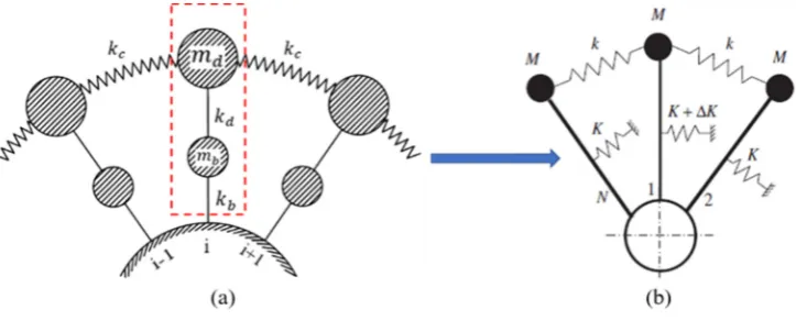
109
When in the air, for each sector of Francis turbine, it consists one piece of crown, one blade and
110
one piece of the band. If simplifying each of them to a lump mass using the method in[8], the system
111
will be multi-coupled, which is very complicated. Little theories about the effect of crack on this
112
system are available in the literature. For the low-order modes of the researched Francis turbine, the
113
crown usually has relatively small modal displacement [6]. If neglecting the crown and seeing the
114
connecting side of blades with it as fixed, the turbine can be simplified to the mode shown in Figure
115
3(a). and k are the blade (modal) mass and (modal) stiffness, respectively. The mass m
116
simulates the effective mass of the corresponding section of the disk(band), and the stiffness k
117
represents the stiffness of the rotor disk(band), whereas the massless spring stiffness k , provides
118
disk coupling between neighboring sectors. This is a mono-coupled system, and its transfer matrix
119
can be obtained using the method in [8]. However, the matrix is still complicated because of too many
120
parameters.
122
Figure 3. Theoretical modes
123
124
As aforementioned, this method indicates that the blades and band have similar modal
125
behaviors with only some parameter differences. A simpler way is to simplify the band and single
126
blade into one lump mass together as shown in Figure 3(b) and each lump mass contains two degrees
127
of freedom, namely band and blade. Therefore, it will have blades dominated modes and band
128
dominated modes. The modal behavior of this system with and without crack has been obtained in
129
[16] and [17], respectively, which can be seen in section 2.2.
130
2.2. Crack induced modal localization in mono-coupled system
131
The whole system has N substructures and each substructure is simplified to a lump mass.
132
Substructures with M mass and K stiffness are mono-coupled with massless springs, which stiffness
133
is k. Substructure-1 is assumed to have a ∆K stiffness change.
134
135
For the tuned system, ∆K 0. The modal shapes can be divided into two categories:
136
137
1, cos ,… , cos − 1 , r 1, … ,2 1 1
138
139
0, sin , … , sin − 1 , r 2, … ,
2 2
140
141
where , 2 − 1 / . The corresponding eigenvalues are
142
143
1 2 1 − cos ∙ 3
144
145
Where ⁄ is the coupling effect and ⁄ is the natural frequency of the
146
undamaged single substructure. The lower and upper limits of passband is
147
148
1 4 4
149
150
Note that except for k equals 1 or N/2 + 1, doublet eigenvalues occur, the corresponding
151
eigenvectors being and (in fact, any linear combination of and is also an eigenvector).
152
For periodic structures, they are usually called r − 1 ND (node diameter) mode. For N odd, N/2 +
153
1 is replaced by (N+ l)/2 in (1-2), and there is only one simple eigenvalue for r = 1.
154
155
When substructure-1 has stiffness change, because of zero substructure-1 deformation of ,
156
these modes will not be affected by the mass or stiffness change. All the rest /2 1 modes will
157
change and become chaos. Unlike the frequencies of other modes changing slightly, the 0 ND will
158
quickly drop out of the pass-band and will be the only localized mode to the damaged sub-structure.
159
For the localized mode, the damaged substructure(substructure-1) will have the largest deformation
and the deformation on other substructures will symmetrically attenuate around substructure-1. The
161
attenuation rate ξ will be:
162
163
ξ 1 ∆ 2⁄ − |∆ 2⁄ | 5
164
165
Where the ∆ ∆ ⁄ is the stiffness loss ratio of the damaged blade. Obviously, the attenuation
166
rate ξ is an odd function of ∆ ⁄ ratio, the higher ∆ ⁄ ,the higher severity of modal localization.
167
The frequency reduction ratio of the localized mode is
168
169
λ 2 1 − 1 ∆ 2⁄ 6
170
171
This procedure indicates that disk(band)-dominated modes also has modal localization to the
172
disk part if the corresponding blade has damage. However, for the real runner, the instability and
173
complicated blade-disk interaction [18] due to the unbalance problem aforementioned may bring
174
many differences.
175
176
3. Simulation setup
177
The intact runner mode is a replica at a reduced scale of 1:10 of a Francis turbine runner with a
178
specific speed of 0.56. The model runner has 17 blades and a diameter of 409 mm. The shape of the
179
runner with the main dimensions is shown in Figrue.2. The material used is a bronze alloy whose
180
properties are given by Table 1.
181
182
First, the intact runner mode will be validated by comparing its modal analysis results in air and
183
water with the experimental results in[5]. Ansys 16.2 was used to handle all the simulations in this
184
paper, and the acoustic FSI technology is used to simulate the added mass effect from surrounding
185
water[6]. The material property of the acoustic body can be seen in Table 2. When the runner is
186
submerged in water, common nodes technology is used at all the FSI interfaces, and the Asymmetric
187
solver is used in the simulation. The distances A and B shown in Figure 1 are 100mm and 45mm,
188
respectively. The upper surface of the water domain was set as zero-pressure surface and all other
189
outside boundaries of water domain were set as rigid walls. The mesh sensitivity is strictly checked,
190
and when the runner is submerged in water, approximately 192,391 tetrahedral elements are used.
191
Because the damping has little effects on the modal behavior of the structure, the structure damping
192
and the viscosity of the acoustic body are neglected[5, 6]. The comparison between the numerical and
193
experimental results in [5] can be seen in Table 3. As seen, good agreement has been obtained.
194
195
196
197
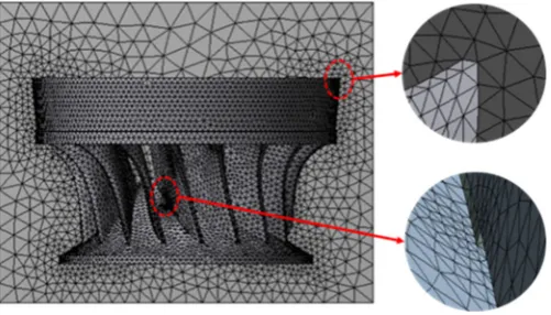
Figure 4. View of the mesh
Based on the validation of the intact runner, a crack is created at the intersection line between
200
one blade and the crown from inside to outside, a location that has been shown to be prone to the
201
occurrence of cracks in the Francis turbine [2]. The crack is represented as a narrow gap, and this is a
202
linear method that has been used in much of the literature [17]. The total length of the intersection
203
line is approximately 120 mm and the crack length in this paper will vary from 0 mm to 100 mm. The
204
mesh density at the crack tip has been especially increased as shown in Figure 4. When submerged
205
in water, the water at the crack clearance is neglected. The effects of the crack on the dynamic
206
behaviors of the runner will be investigated.
207
208
Table 1. Properties of the runner material
209
Properties Young’s modulus Density Poisson’s ratio Value 110 GPa 8300 kg/m3 0.34
210
Table 2. Properties of the acoustic body
211
Properties Sonic speed Density Value 1483 m/s 1000 kg/m3
212
Table 3. Results of the experimental and numerical modal analysis
213
SIM-AIR: Simulation in air (unit: Hz) EXP-AIR: Experiment in air SIM-RATIO: SIM-WATER/SIM-AIR
214
SIM-AIR EXP-AIR SIM-WATER EXP-WATER SIM-RATIO EXP-RATIO
2ND 357.00 373.51 275.89 279.50 0.773 0.748 0ND 408.38 417.50 374.73 370.50 0.907 0.887 3ND 475.98 487.53 338.26 331.25 0.711 0.679 4ND 563.50 573.75 369.36 359.00 0.656 0.626 1ND 606.20 616.75 489.62 481.50 0.808 0.781 5ND 634.85 649.75 391.65 400.00 0.617 0.616
215
4. RESULTS AND DISCUSSION
216
4.1. Modal behavior
217
4.1.1 Natural frequencies and modal shapes
218
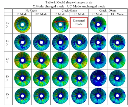
The modal shapes without a crack, with a 60 mm crack and with a 100 mm crack in the air and
219
water can be seen in Table 4 and Table 5, respectively. For each simulation case, the modal
220
displacement is divided into nine levels from high to low so that they can be compared together. The
221
changes in both the natural frequency and the frequency-reduction ratios with the crack length in air
222
and water can be seen in Figure 5 and Figure 6, respectively.
223
224
Obviously, the modal shapes are different in the air and water for the same ND modes with the
225
same crack length, which has also been shown in [6]. This may be mainly because the blades and the
226
band suffer from different added mass factors [5] in water for such structures with the different parts
227
separated enough to have their own dominant modes. Due to the modal shape change from air to
228
water, the frequency changes with increasing crack length in air and water will also be very different,
229
as shown in Figure 5 and Figure 6. Therefore, the Francis turbine in water can be seen as a new
bladed-230
disk structure with the band, crown and blades having different densities. Of course, due to the close
231
distance between the blades, each may affect the vibration of nearby blades through hydraulic
232
force[19], which may cause the system to be multi-coupled[8]. However, for the researched modes,
233
this coupling stiffness from hydraulic force ought to be very small compared with the coupling
234
stiffness from band deformation and thus its effect may be very limited. Therefore, the effect of a
235
crack on the modal behavior in air and water ought to show many similarities, which can be seen in
236
the following analysis.
From the modal shapes and natural frequencies, the singlet 0ND and one of the doublet modes
239
of each ND will change relatively more, while the remaining one of the doublet mode of each ND
240
will change relatively less. Generally, for actual turbines, there are no substructures that are without
241
any deformation. Therefore, there are no modes that are completely unaffected by the crack.
242
However, one of the doublet modes of each ND continues to change relatively more and the other
243
one changes much less, which means the principle of the change in modes due to the crack is still in
244
accordance with the theoretical analysis. In the following parts, the modes changing more are referred
245
to as changed modes, and modes changing less are referred to as unchanged modes.
246
247
248
Figure 5. Natural frequency changes and change ratios in air
249
250
Table 4. Modal shape changes in air
251
C.Mode: changed mode UC. Mode: unchanged mode
252
No Crack Crack 60mm Crack 100mm C. Mode UC. Mode C. Mode UC. Mode C. Mode UC. Mode
0 N D
1 N D
2 N D
3 N D
4 N D
253
When comparing the modal shape changes of the changed and unchanged doublet modes of
254
each ND with the change in crack length, for most ND modes the changed mode usually originates
255
from the one with low deformation on the damaged blade, and the damaged blade is close to the
256
zero-displacement node. In contrast, for the 1ND and 8ND modes, which have nearly zero
257
deformation blades, the changed mode usually originates from the one with high deformation on the
258
damaged blade, and the damaged blade is far from the zero-displacement node.
259
260
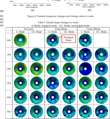
Figure 6. Natural frequency changes and change ratios in water
261
262
Table 5. Modal shape changes in water
263
C.Mode: changed mode UC. Mode: unchanged mode
264
No Crack Crack 60mm Crack 100mm C. Mode UC. Mode C. Mode UC. Mode C. Mode UC. Mode
0ND
1ND
2ND
3ND
4ND
5ND
265
The modal shape changes with the increase in crack length are not that regular, which may be
266
because of the vibration instability mentioned above under the complicated high-intensity interaction
267
between the blades and disk. Due to the differences in vibration motion of the different ND modes,
268
the changes can vary significantly. For all the unchanged modes, the modal shapes may also become
269
distorted to some extent with an increase in crack length. Apart from the unchanged 1ND, which has
270
low deformation at the damaged blade, the damaged blade is prone to having a large deformation at
271
the beginning part of the crack. This high deformation can cause the energy to concentrate at that
272
part, which will induce deformation degeneration at the band and other blades.
273
274
For the changed modes, the modal shape changes are even more irregular than those of the
275
unchanged modes. Sometimes, under certain crack lengths, the highest deformation may appear at
276
blades near the damaged blade, but when the crack length is very large, it will finally transmit to the
277
damaged blade, like the changed 2ND and 3ND mode in air. Obviously, both in the air and in water,
278
the changed 2ND mode has a high deformation concentration in the band near the damaged blade.
279
This is the only mode that has a deformation concentration on the band near the damaged blade.
280
Therefore, it ought to be the localized mode. The concentration usually is at the band piece next to
281
the damaged blade sector when the crack is short, but it will finally transmit to the damaged blade
282
sector and the localization becomes very strong when the crack is long.
283
284
The 3ND in the air with a crack length of 100 mm is a special case, which has a high deformation
285
concentration at the damaged blade with strong deformation degeneration at the band and other
286
blades. This mode may be not the localized mode because the band deformation has no concentration
287
near the damaged blade. The origin of this mode may be the vibration instability mentioned earlier.
288
The 3ND mode in water presents an interesting situation. When the crack is not too long, e.g., 60 mm,
289
this mode shows a high deformation concentration on the damaged blade with deformation
290
degeneration on the band. However, when the crack is long, e.g., 100 mm, the modal shape of the
291
changed 3ND becomes similar to that of the 2ND. From Figure 5, the natural frequency of the changed
292
3ND with a 100 mm crack is close to that of the 2ND mode. This means that when the changed modes
293
are close to other modes with the reduction of frequencies, the modal shapes will become similar
294
with the modes that they will pass.
295
296
For the unchanged modes, the frequency reduction ratios are usually lower than 5% when the
297
crack length is 100 mm. For some modes, such as the unchanged 1ND, the frequency reduction ratio
298
can be as low as 0.1%. For the changed modes, the localized mode usually has a relatively
high-299
frequency reduction ratio. When the crack length is 100 mm, the frequency reduction ratios of the
300
localized 2ND can be as high as 16% in air and 26.5% in water. Though the changed 3ND mode in air
301
has a high deformation concentration on the damaged blade when the crack length is 100 mm, its
302
frequency reduction ratio is much lower than the localized 2ND. This may have a relationship with
303
the damaged blade deformation, which means that for the changed 3ND mode, the deformation
304
concentrates on the beginning part of the crack in the damaged blade and this modal shape of the
305
damaged blade may not cause a high stiffness reduction ratio. However, when in water with a crack
306
length of 60 mm, the frequency reduction ratio of the 3ND mode is higher than that of the localized
307
2ND mode. In addition to the damaged blade having a modal shape with the highest deformation at
308
its middle part, the deformation concentration degree may also contribute to it, which means the
309
changed 3ND has a higher deformation concentration degree than the localized 2ND mode in water.
310
311
As mentioned earlier, when the changed modes are close to other modes with the reduction of
312
frequencies, the modal shapes will become similar with the modes that they will pass. This
313
phenomenon may have large effects on the frequency reduction ratios of the changed modes. In
314
water, this phenomenon can be more significant than in air because the frequencies of different modes
315
are closer. For the changed 3ND, 4ND and 5ND modes in water as well as the changed 5ND mode in
316
air, when this phenomenon occurs with an increase in crack length, the frequency reduction is greatly
decreased. Overall, the natural frequency changes for all ND modes are limited. This is due to two
318
main reasons. On the one hand, though the band is like a thin ring, the couplings between
319
neighboring sectors are still very high. On the other hand, the blades are firmly constrained by the
320
band and the crown, which may reduce the stiffness reduction ratio. For different modes, the
321
frequency reduction ratios can vary significantly.
322
323
In reality, the runner is connected to the shaft. By assuming that the shaft is nearly rigid, a fixed
324
support is given to the top surface of the crown, as shown in Fig. 9(support A), and the modal shapes
325
under the fixed support in the air are shown in Table 6. Due to the fixed support, the 0ND, 1ND and
326
2ND modes were reduced from 408.38 Hz, 605.84 Hz and 356.95 Hz to 256.43 Hz, 301.43 Hz and
327
369.27 Hz, respectively. This means that these three modes have more deformations on the crown
328
part, particular the 0ND and 1ND. There are also large changes in the modal shapes of 0ND and 1ND.
329
The natural frequencies of the higher ND modes are almost unaffected by the fixed support.
330
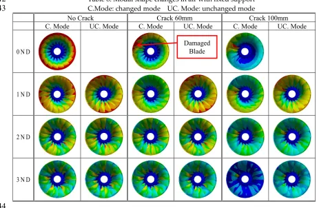
Obviously, the 0ND mode quickly becomes localized with the increase in crack length. The
331
interesting thing about the 1ND is that it also shows some localization, even though the degree of
332
localization is much less than 0ND. The 2ND mode no longer has localization. The 3ND mode still
333
shows a strong deformation concentration at the damaged blade when the crack is 100 mm. From the
334
above analysis, the mode with the lowest natural frequency is most prone to localize. This may have
335
a relationship with the blade-disk interaction property and the mode with the lowest frequency is
336
just at its veering point [18]. That 1ND shows some localization may be because of its relatively low
337
frequency and the strong instability of its vibration. When there is no fixed support at the crown, the
338
1ND mode is at high-frequency area, and no localization occurs to it. Considering the low degree of
339
localization of 1ND, it may be considered that there is still only one localized mode.
340
341
Table 6. Modal shape changes in air with fixed support
342
C.Mode: changed mode UC. Mode: unchanged mode
343
No Crack Crack 60mm Crack 100mm C. Mode UC. Mode C. Mode UC. Mode C. Mode UC. Mode
0 N D
1 N D
2 N D
3 N D
344
4.1.2 FFT of modal shapes and the localization factor
345
The modal shape change due to a crack can also be described using a Fast Fourier Transform
346
(FFT) of the modal shape. The first step of this procedure is to choose the sample point to represent
347
the modal shape change. First, the sample point is chosen as the intersection point of the trailing edge
348
and the band for each blade. Therefore, 17 sample points were obtained, and the modal displacement
349
variation of these 17 points for each mode was used for FFT. The FFT results of the changed 2ND,
350
unchanged 2ND, unchanged 3ND and changed 3ND in air for crack lengths of 0 mm, 60 mm and 100
351
mm are shown in Figure 7(a), (b), (c) and (d), respectively. Each modal shape can be seen to be
352
synthesized by different ND harmonic waveforms with different magnitudes. For each ND, its value
353
was plotted by the percentage of its magnitude to the sum of the magnitudes of all ND waveforms.
354
355
356
Figure 7. FFT results to the modal shapes
357
358
Without a crack, each modal shape clearly contains only one waveform. With the increase in
359
crack length, the percentage value of this original waveform will continue to decrease and other ND
360
waveforms will appear with increased percentage value. For the unchanged modes, the decrease in
361
the original ND waveform and the increase other ND waveforms are very insignificant, while for the
362
changed modes, they are much more significant, particular for the localized mode and the mode with
363
strong deformation concentration to the damaged blade (like the changed 3ND in Figure 7(d)). The
364
values of the new appearing ND waveforms usually decrease with their separation from the original
365
ND waveform.
366
367
For a Francis turbine, the excitation from the hydraulic force is due to the rotor-stator interaction
368
and the excitation is order excitation. To make the runner resonant, both the frequency and the ND
369
of the excitation should be in accordance with the runner mode. This is to say that only the mode
370
with the same ND can extract energy from the excitation force. When a crack is present, other ND
371
waveforms start to appear. This means that the mode now can not only be excited by the original ND
372
excitation but also be excited by other ND excitations. With an increase in the crack length, the
373
decrease in the original ND percentage value means the ability to extract energy from the
374
corresponding ND excitation decreases and the increase in the other ND percentage values means
375
the ability to extract energy from the corresponding ND excitation increases[20]. However, the FFT
376
value change may quite depend on the sample points positions because with the crack, the
377
deformations on the blades, particular the damaged blade, become very ununiform. With other
378
groups of sample points, the FFT results may vary a lot and become not that regular. However, using
those sample points may be not appropriate because of the locally unregular deformation change on
380
the damaged blade and it may be better to use the sample points on the band.
381
382
The maximum response under order excitation not only depends on the FFT value change but
383
also depends on the Localization Factor(LF) [21] change. The LF is defined as:
384
385
−
100% 7
386
387
Where is the maximum modal displacement of one mode without crack and is the
388
maximum modal displacement of the mode with crack. The LF describes the frequency response
389
function(FRF) change due to crack under point excitation for one mode. Of course, the damping is
390
not considered in the modal analysis and this may have some effects on the LF values. With damage,
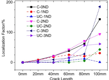
391
the deformation will have concentrations, which will induce the increase of the modal displacement.
392
When the frequency change due to crack is not that too large, the deformation concentration will
393
increase the LF value. From Figure 8, for most modes, the LF will increase with the crack length
394
increase. The increases for changed modes are much more significant than the unchanged modes due
395
to higher deformation concentrations. When the crack length is high, the modal shape changes may
396
be very complicated and the LF values may decrease, like the unchanged 1ND mode from crack
397
80mm to 100mm.
398
399
However, for an actual Francis turbine, the excitation is order excitation and the excitation
400
energy depends on the FFT value in Figure 7. If the FFT value increases, and the LF value increases
401
with increasing crack length, the maximum deformation change of the forced response will increase.
402
If the FFT value decreases and the LF value increases with increasing crack length, the maximum
403
deformation change of the forced response will depend on the change rates of the two values.
404
405
406
Figure 8. LF value changes with the crack length
407
408
4.2. Forced response
409
The forced response was carried out through harmonic response analysis. The top face of the
410
crown was fixed, and the amplitude of dynamic pressure was 0.01Mpa (seen in Figure 9). Here we
411
use the constant pressure to research the property change of the runner, which is a common method
412
used in[10, 12, 13, 17]. In [17], the analytic method was used to analyze the forced response of the
413
localized 0ND in mono-coupled lumped parameter system. However, the analysis on the forced
414
responses of other nonlocalized modes was very little. Furthermore, the analytical method is very
415
complicated and not very intuitionistic. For real Francis turbine, the responses may also be not as
416
regular as those in lumped parameter system. In this paper, the forced responses will be analyzed
417
based on the modal shape FFT results and LF value changes, which is more intuitionistic and easier
418
to understand. Dynamic pressures were applied to the pressure side of each blade. To get certain ND
order excitation, there were corresponding phase changes between neighboring blades. Because in
420
water, the dynamic behaviors of the runner have no essential differences with those in the air, the
421
analysis was only done for the runner in the air. The forced responses under 3ND excitation is shown
422
in Figure 10.
423
424
The experimental damping ratio of 3ND mode 0.0068 was implemented because the 3ND mode
425
has the highest response and damping ratio has larger effects on the higher response. The FFT and
426
LF values obtained above are based on the modal analysis without fixed support on the crown.
427
However, for 3ND mode, the effects of fixed support are very little. Therefore, they are still used to
428
explain the forced response changes.
429
430
431
Figure 9. Boundary conditions and loads
432
433
For 3ND excitation, the unchanged 3ND mode and the changed 3ND mode certainly have the
434
highest responses (shown in Ⅱ of Fifure.10). For the undamaged runner, there is only one peak due
435
to the same natural frequencies of the changed and unchanged 3ND modes. With the increase of the
436
crack length, these two modes become separated, and two peaks appear. The first peak corresponds
437
to the changed mode and the second peak corresponds to the unchanged mode. For the changed 3ND
438
mode, the response at crack 20mm is the highest, which means the increase of the LF value is faster
439
than the decrease of 3ND FFT percentage value from 0mm to 20mm. From 20mm to 80mm, the
440
response decreases gradually, which is because the 3ND FFT value of this mode decreases fast, while
441
the LF value increase moderately during the progress. From 80mm to 100mm, there is a drastic
442
response increase, which is due to the drastic LF value increase as shown in Fifure.8. For the
443
unchanged 3ND mode, the response with 20 mm long crack is also highest. When with 20mm crack,
444
the peaks of changed and unchanged modes are very close, and they may affect each other’s response
445
to some extent. From 20 mm to 100 mm, the response change is not that regular and reaches its
446
minimum at 100mm. From Figure 8, the LF value of the unchanged 3ND mode increases drastically
447
from 20mm to 80mm, which may be the reason why the response at 60mm is higher than that at
448
40mm. At 40mm, the peaks of changed and unchanged modes are approximately the same, this is
449
because the LF value of the changed mode is a little higher while the FFT value a little lower compared
450
with those the unchanged mode. At 60mm or 80mm, the peak of the unchanged mode is much higher
451
than that of the changed mode due to the both higher LF and FFT values. At 100mm, the levels of
452
these two peaks are close again.
453
454
For the 1ND mode without crack under 3ND excitation, the response (seen in Ⅰ of Figure 10)
455
certainly is very low. With the increase of crack length, the response of the changed 1ND mode
456
increases drastically. This is because both the 3ND FFT value and the LF value of 1ND mode increase
457
with the crack length. The response of unchanged 1ND under 3ND excitation is much lower, and
458
only a little peak appears when the crack is 100mm. The response changes of 0ND, 2ND and 4ND
459
modes are similar with that of 1ND. However, the responses of 0ND and 4ND at crack 100mm are
460
much higher than that of 2ND. This is because of the great increases of the LF values due to the high
deformation concentrations of these two modes (see Figure 8). When the crack length is not that high,
462
like less than 60mm, all these peak levels are still limited due to the moderate increases of the LF and
463
FFT values.
464
465
Figure 10. Forced responses under 3ND excitation
466
467
Overall, both for the changed and unchanged modes under the same ND excitation, with the
468
increase of crack length, the responses usually increase first and then decrease, even though the
469
increase and decrease progress are not monotone. This change progress is similar to the force
470
response changes of the localized mode in lumped parameter system with crack severity[17]. Except
471
the localized 0ND, the forced responses of other modes decrease with apart from 3ND. This is because
472
the FFT percentage values of new appearing ND waveforms usually decrease with apart from the
473
original ND waveform as aforementioned. This point is very similar to the forced response changes
474
of localized 0ND with excitation order in lumped parameter system, which has a decreased response
475
with increase the ND of excitation (apart from 0ND)[17]. Therefore, the forced responses of localized
476
and nonlocalized modes indeed share many similarities. From the response peak changes of all the
477
modes, the method that using the FFT and LF value changes to explain the response changes is
478
basically appropriate.
479
480
For the researched Francis turbine, when the crack length is high, the frequency reduction ratios
481
can be higher than 20%( mainly referring to the localized mode or the modes with strong deformation
482
concentrations on the damaged blade). However, when the crack is not that large, the natural
483
frequency reduction ratios are usually less than 10%. For this type of machine, there is usually a safety
484
margin in the operation to avoid resonance, such as 20% of the natural frequency (corresponding to
485
the ND of the RSI excitation). Therefore, it is very difficult for the natural frequency to fall to the
486
operating area to be excited and to be detected by the current monitoring system.
487
488
Though the responses of other modes (not corresponding to the ND of the RSI excitation)
489
increase with crack length and these modes are in the operating region, when the crack length is not
490
high enough (often less than 60 mm), the response increases are still limited. Because the peak
491
increases due to a crack are limited, they might very easily be confused with a load change, and it
492
can be difficult to activate the vibration alarm of the turbine. Another very important thing is that the
current monitoring system is usually at the bearing of the turbine. The vibration of runner must be
494
transmitted to the bearing through the shaft, and the vibrations are also easily confused with the
495
bearing effect. The response used in this paper is the maximum response of the runner, which is also
496
used in many other papers[10, 12, 13]. However, due to the vibration being transmitting to the
497
monitoring system, the equivalence between the maximum local response increase due to a crack and
498
the vibration increase captured by the monitoring system is still doubtful.
499
500
For the Francis turbine shown in Figure 1, its modal behavior is still not that clear and the crown
501
may have a high deformation. Under this situation, it will be multi-coupled, and more than one
502
localized mode may appear. Doublet modes can still be divided into changed modes and unchanged
503
modes, just as for the impeller in[13]. However, the higher deformation at the crown will greatly
504
increase the coupling stiffness, which will cause the natural frequency reduction ratios and the
505
response changes to be much lower (5-6) [17]. This will greatly increase the monitoring difficulty and
506
may be the reason why a so large crack was not detected by the monitoring system.
507
508
The value of the current research is twofold. First, it clarifies the effect of a crack on the dynamic
509
behavior of a Francis turbine from the viewpoint of vibration localization and the challenge of crack
510
monitoring. Second, this research can provide some references for more advanced crack-monitoring
511
technologies. Though the frequency deviations are low, they maybe can be captured by more
512
advanced monitoring technologies. David Valentín et al [15]has done some researches on the
513
feasibility of detecting natural frequencies of hydraulic turbines while in operation using strain
514
gauges. Therefore, the natural frequency changes of the runner in operation maybe can be detected
515
more accurately and through these changes, the crack maybe can be detected much earlier. Of course,
516
the phenomenon that the modal shape of the changed mode may become similar with another mode
517
when their frequencies are close as aforementioned should be paid special attention to during the
518
progress, because when the natural frequencies and modal shapes are similar, they are very easy to
519
be confused, which may greatly increase the monitoring difficulty. It seems that the lowest frequency
520
mode is ideal for monitoring because it is usually the localized mode which has highest frequency
521
reduction ratio and is not affected by the above-mentioned phenomenon. However, due to the lowest
522
frequency, its frequency value change may be also very low, which makes it easy to be confused by
523
the monitoring error. While the higher frequency modes have advantages in this aspect. R.A. Saeed
524
et al [22] has done some works on the crack monitoring using artificial intelligence technology based
525
on the maximum forced responses of the runner. However, the maximum response may be difficult
526
to obtain in real case. Anyway, this technology has developed very fast during the past few years and
527
shows great potential[23]. Due to the low frequency and response changes as shown in the above
528
analysis, this technology combined with the on-runner measurements is specially recommended for
529
further research in the future.
530
531
CONCLUSIONS
532
The modal behaviors and forced responses of a Francis runner model with a crack were studied
533
numerically in this paper and the crack-induced vibration localization theory was used to explain the
534
dynamic behavior changes. Some main conclusions are as follows:
535
536
For the studied Francis runner model, the crown has a low modal displacement. Therefore, it
537
almost can be seen as a mono-coupled system. There is usually only one localized mode and when
538
the crack length is high, strong localization can occur. The mode with the lowest natural frequency is
539
easiest to localize. The singlet modes and one of the doublet modes for each ND will change much
540
more, and the remaining doublet modes will change much less. All these matches the theories well.
541
However, perhaps due to the vibration instability, the modal shape changes are not that regular, and
542
some non-localized modes may show strong deformation concentrations on the damaged blade. The
543
frequency reduction ratios of the changed modes are relatively higher than those of unchanged
modes. The localized mode or the modes with strong deformation concentrations on the damaged
545
blade usually have the highest natural frequency reduction ratios. The modal shapes and frequency
546
reduction ratios in water are different from those in the air because the band and blades suffer from
547
different added mass factors in water. The modal shape of a changed mode may become similar with
548
another mode when their frequencies are close. The FFT percentage value of the original ND for one
549
mode usually decreases with the increase in crack length, while the FFT percentage values of other
550
NDs usually increases with the increase in crack length. The LF values usually increase with an
551
increase in crack length and the LF value changes of the changed modes are usually higher than those
552
of the corresponding ND unchanged modes.
553
554
For one mode under the same ND excitation with constant pressure, the forced response usually
555
first increases and then decreases with the increase in crack length, but the progress may not be
556
monotone. The response of one mode under other ND excitations will increase gradually and the
557
response can be very high when the crack is long. The method that using the FFT and LF value
558
changes to explain the response changes is basically appropriate.
559
560
Though the band is similar to a thin ring, it is still very stable. Therefore, the coupling stiffness
561
is very high, which makes the natural frequency reduction ratios less than 10%, and the forced
562
response changes are limited when the crack is not long enough. These are the reasons why the crack
563
is difficult to be monitored in this type of runner. The research in this paper can provide some
564
references for more advanced monitoring technologies.
565
566
Author Contributions: Ming Zhang did the simulation and wrote the paper; Xingfang Zhang
567
contributed jointly by supervising the overall work and overall structure of the paper; Weiqiang Zhao
568
helped to improve the quality of some pictures and the language of the paper.
569
570
Acknowledgments: The present research work was financially supported by China Scholarship
571
Council.
572
573
Conflicts of Interest: The authors declare no conflict of interest.
574
575
Nomenclature
576
FFT Fast Fourier Transform LF Localization Factor
577
Blade modal mass Disk modal mass
578
Blade modal stiffness Disk modal stiffness
579
Coupling stiffness N Number of blades
580
M Mass of the substructure K Stiffness of the substructure
581
∆K Stiffness change of the substructure Cosine category of modal shapes
582
Sine category of modal shapes ξ Attenuation rate
583
r Engeon order ∆ Stiffness loss ratio
584
ND Nodal Diameter Coupling stiffness
585
Lower limit of the pass-band Upper limit of the pass-band
586
q Modal displacement of the substructure
587
, Phase change of neighboring substructures
588
ω Natural frequency of the undamaged r − 1 ND mode
589
Natural frequency of the undamaged substructure
590
λ Frequency reduction ratio of the localized mode
591
maximum modal displacement of one mode without crack
592
maximum modal displacement of one mode without crack
References
595
1. Liu, X., Y. Luo, and Z. Wang, A review on fatigue damage mechanism in hydro turbines.
596
Renewable and Sustainable Energy Reviews, 2016. 54: p. 1-14.
597
2. Frunzǎverde, D., et al., Failure analysis of a Francis turbine runner. IOP Conference Series: Earth
598
and Environmental Science, 2010. 12.
599
3. Flores, M., G. Urquiza, and J.M. Rodríguez, A Fatigue Analysis of a Hydraulic Francis Turbine
600
Runner. World Journal of Mechanics, 2012. 02(01): p. 28-34.
601
4. Egusquiza, E., et al., Condition monitoring of pump-turbines. New challenges. Measurement,
602
2015. 67: p. 151-163.
603
5. Rodriguez, C.G., et al., Experimental investigation of added mass effects on a Francis turbine
604
runner in still water. Journal of Fluids and Structures, 2006. 22(5): p. 699-712.
605
6. Liang, Q.W., et al., Numerical simulation of fluid added mass effect on a francis turbine runner.
606
Computers & Fluids, 2007. 36(6): p. 1106-1118.
607
7. Cai C W, Cheung Y K, Chan H C. Mode localization phenomena in nearly periodic systems[J].
608
Journal of applied mechanics, 1995, 62(1): 141-149.
609
8. Ottarsson G, Pierre C. Vibration localization in mono-and bi-coupled bladed disks-a transfer
610
matrix approach[C]//34th Structures, Structural Dynamics and Materials Conference. 1993: 1492.
611
9. Saito A, Castanier M P, Pierre C. Effects of a cracked blade on mistuned turbine engine rotor
612
vibration[J]. Journal of vibration and acoustics, 2009, 131(6): 061006.
613
10. Kuang J H, Huang B W. The effect of blade crack on mode localization in rotating bladed disks[J].
614
Journal of sound and vibration, 1999, 227(1): 85-103.
615
11. Jung C, Saito A, Epureanu B I. Detection of cracks in mistuned bladed disks using reduced-order
616
models and vibration data[J]. Journal of Vibration and Acoustics, 2012, 134(6): 061010.
617
12. D'Souza, K., A. Saito, and B.I. Epureanu, Reduced-Order Modeling for Nonlinear Analysis of
618
Cracked Mistuned Multistage Bladed-Disk Systems. AIAA Journal, 2012. 50(2): p. 304-312.
619
13. Wang, S., et al., Reduced-order modeling for mistuned centrifugal impellers with crack
620
damages. Journal of Sound and Vibration, 2014. 333(25): p. 6979-6995.
621
14. Valero, C., et al., Modal behavior of a reduced scale pump turbine impeller. Part II: Numerical
622
simulation. IOP Conference Series: Earth and Environmental Science, 2010. 12.
623
15. Valentin, D., et al., Feasibility of Detecting Natural Frequencies of Hydraulic Turbines While in
624
Operation, Using Strain Gauges. Sensors (Basel), 2018. 18(1).
625
16. Wei S T, Pierre C. Localization phenomena in mistuned assemblies with cyclic symmetry part I:
626
free vibrations[J]. Journal of Vibration, Acoustics, Stress, and Reliability in Design, 1988, 110(4):
429-627
438.
628
17. Fang, X., et al., Crack induced vibration localization in simplified bladed-disk structures. Journal
629
of Sound and Vibration, 2006. 291(1-2): p. 395-418.
630
18. Castanier, M.P. and C. Pierre, Modeling and Analysis of Mistuned Bladed Disk Vibration:
631
Current Status and Emerging Directions. Journal of Propulsion and Power, 2006. 22(2): p. 384-396.
632
19. Valentín, D., et al., Experimental Study of a Vibrating Disk Submerged in a Fluid-Filled Tank
633
and Confined With a Nonrigid Cover. Journal of Vibration and Acoustics, 2017. 139(2).
634
20. Castanier, M.P. and C. Pierre, Using Intentional Mistuning in the Design of Turbomachinery
635
Rotors. AIAA Journal, 2002. 40(10): p. 2077-2086.
636
21. Wang J J, L.Q.H., Methods and Applications of reduction modeling for mistuned bladed disk
637
vibration in aero-engine. 2009: Nation Defense Industry Press, China.
638
22. Saeed, R.A., A.N. Galybin, and V. Popov, 3D fluid–structure modelling and vibration analysis
639
for fault diagnosis of Francis turbine using multiple ANN and multiple ANFIS. Mechanical Systems
640
and Signal Processing, 2013. 34(1-2): p. 259-276.
641
23. Liu, R., et al., Artificial intelligence for fault diagnosis of rotating machinery: A review.
642
Mechanical Systems and Signal Processing, 2018. 108: p. 33-47.
![Figure 1 . Francis turbine blade failure case reported by D Frunzăverde, 2010[2].](https://thumb-us.123doks.com/thumbv2/123dok_us/1000788.1599891/2.595.221.396.157.296/figure-francis-turbine-blade-failure-case-reported-frunzaverde.webp)
![Figure 2. Geometry of the model and the view submerged in water [5]](https://thumb-us.123doks.com/thumbv2/123dok_us/1000788.1599891/3.595.114.501.75.232/figure-geometry-model-view-submerged-water.webp)