1
A REVERSE TRANSMISSION APPROACH FOR MULTI-HOP
ROUTING IN WIRELESS SENSOR NETWORK
1
NILAYAM K KAMILA, 2PRASHANTA K PATRA, 3PRBODHA K PRADHAN, 4PRASANT K PATTNAIK,
1
I.T. Analyst, TATA Consultancy Services, Bangalore, Karnataka, India-560066
2
Professor & Head, Department of Comp. Sc & Engg. CET, Bhubaneswar, India -751003
3
Asst. Prof., Department of Comp. Sc & Appl., Regional College of Mgmt., Bhubaneswar, India -751023
4
Professor & Head, Department of Comp. Sc & Engg., KIST, Bhubaneswar, India -752050
E-mail: [email protected], [email protected], [email protected],
ABSTRACT
Sensor network nodes are spreaded over specific area with limited battery energy, low computational capacity and restricted communication bandwidth. In Sensor networks, the cluster-based routing algorithms are used to reduce the energy consumption of nodes and prolong the network lifetime [4, 5, 6, 7]. In most cluster-based algorithms, a predefined number of clusters or cluster heads is required. In some cases the nodes’ density and distribution significantly affect clustering techniques applied in wireless sensor networks. In this work , we propose a routing approach namely as Reverse Transmission Approach (RTRA) where we have established a reverse transmission for some intermediate node which are located in the path of the cluster head to base station. Again, the mathematical analysis gives a suitable threshold value for intermediate nodes. The proposed scheme is compared with existing related works through the simulation studies.
Keywords: Sensor Networks, Multi-Hop, Hierarchical routing
1. INTRODUCTION
The recent technological advances in micro-sensor and wireless communication make it possible to deploy a low power, inexpensive sensor in large scale. The Networking among themselves has revolutionized the information gathering and processing.
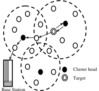
The base station typically serves as a gateway to some other networks. It provides powerful data processing, storage unit, and an access point to the
sensor nodes in its network. Sensor nodes sense their environment for specific targets, collect data and transmit/receive to/from the base station as shown in figure 1. Moreover, they have only short-range transmission. The nodes must be capable of self organize and be able to constantly maintain their connectivity within the network. Especially in Sensor network, the nodes are resource-constrained devices and participate in the network until their battery has not been depleted. When all sensors die, the network is no more available. Due to small size and random deployment of Sensor nodes, it becomes difficult to repair or maintain these nodes periodically. Hence the traditional routing protocols deployed in wired networks and ad hoc networks are not suitable for the sensor networks.
2. REVIEW OF RADIO MODEL OF WSN
AND ANALYSIS OF EXISTING RELATED ROUTING PROTOCOLS
2.1 Radio model of WSN nodes
A typical wireless sensor networks (WSN) node may constitute of four units such as data processing unit, sensor unit, wireless communication unit and power unit [20].We consider the radio model [18] Target
Sensor
Base Station
User Internet
2 where the power consumed in transmitting a k-bit message through a distance d-unit is calculated by Equation (1), while power consumed in receiving a k-bit message is calculated by Equation (2).
2
(
, )
tr d te d ta d
E
p d
=
ε
p
+
ε
p d
(1)(
)
r d r d
E p
=
ε
p
(2)Where
ε
teandε
rmeans the power dissipated torun the transmitter or receiver circuitry and
ε
tais the power for the transmit amplifier.2.2 LEACH[18]
LEACH is a protocol based on clustering hierarchy architecture. In this protocol, nodes are organized into different clusters each of which has a cluster-head and each cluster-cluster-head fuses data from its members before transmitting them to the base station. Sensors elect themselves to be local cluster-heads at any given time with a certain probability. In order to avoid cluster-heads dissipating too much power, cluster-head election and network rebuilding run periodically. And LEACH is built on the following two assumptions: 1) the base station is fixed and is far from the sensors; 2) All nodes in the network are homogeneous and energy-constrained. The operation of LEACH is broken up into rounds, where each round begins with a set-up phase, when the clusters are organized, followed by a steady-state phase, when data transfers to the base station occur. In set-up phase, cluster-heads are selected randomly and the randomicity ensures the high energy-consumption for data transmitting between cluster-heads and the base station is distributed among all nodes in the network evenly. As a node is elected to be cluster-head, it broadcasts an advertisement message which contains the information qualifying for the cluster-head. The other non-cluster-head nodes decide which cluster to join according to the strength of the advertisement signal. And the cluster-head advertisement heard with the largest signal strength is the cluster-head to which it belongs. Then it transmits a message back to the cluster-head to inform that it will be a member of the cluster.
2.3 PEGASIS[10]
Power-Efficient Gathering in Sensor Information Systems (PEGASIS) is a near optimal chain-based protocol. The basic idea of the protocol is that in order to extend network lifetime, nodes need only communicate with their closest neighbors and they take turns in communicating with the base-station.
When the round of all nodes communicating with the base-station completes, a new round will start and so on. This reduces the power required to transmit data per round as the power draining is spread uniformly over all nodes. Hence, PEGASIS has two main objectives. First, increase the lifetime of each node by using collaborative techniques and as a result the network lifetime will be increased. Second, allow only local coordination between nodes that are close together so that the bandwidth consumed in communication is reduced. Unlike LEACH, PEGASIS avoids cluster formation and uses only one node in a chain to transmit to the BS instead of using multiple nodes.
2.4 Issues Related to LEACH and
PEGASIS [23]
LEACH and PEGASIS are two popular protocols under hierarchical based routing techniques. LEACH has an improvement in energy consumption over direct communication [24], and having the following issues.
1. Unbalanced energy load and large unnecessary energy dissipation.
2. Redundant data transmission in network, to/from intermediate nodes to cluster heads
PEGASIS has better performance over LEACH and is also having the following issues [10].
1) PEGASIS avoids energy dissipation of cluster-rebuilding, but each node should be aware of the energy remaining status of its neighbors
2) Data of those nodes far away from the leader will be forwarded many times through the chain and it will cause long time delay.
3. OUR PROPOSED REVERSE
TRANSMISSION(RTRA) SCHEME
3 instead of sending the data towards the recent cluster head as shown in figure 3.
The reverse transmission decision is to be taken by the intermediate nodes based on the residual energy and the distances between the nodes and the respective cluster heads. Also the decision function depend on the packet size. The intermediate nodes are to be informed regarding this reverse transmission formalism after the first round of data transmission completed by the respective cluster head.
The objective of RTRA approach is to minimize the energy dissipation during the data transmission to these special intermediate nodes. In this proposed RTRA scheme, the redundant transmission between the intermediate nodes to cluster head and again from cluster head to the same intermediate nodes for data transmission towards the base station is avoided.
Hence the redundant data transmission is minimized and the energy dissipation is reduced in the proposed scheme.
The process flow for the RTRA approach is shown in figure 4.The intermediate nodes, which are located on the path between a cluster head and base station, calculate the critical distance factor
' cc
∆
(Ref equation (5) of section 4).This value is compared with a Threshold value (ξ
), based on which the intermediate node forwards the data packets to its own cluster head or to the nearest neighbour towards the base station.Assumptions:
cj
d
: Distance between cluster head and the jth-nodecj
d
: Distance between cluster head c and next hupcluster head c’ towards the base station.
n
: Total number of nodes in a cluster under consideration.Base Station
Cluster head Target
Figure 2: Data Transmission using proposed RTRA Approach
No
Yes Network Setup and cluster head selection
Calculate the distances dic and dic’
Calculate the critical distance
disfference
∆
cc'Is
'
?
cc
ξ
∆ <
Send data to nearest cluster head(ch’) Send data to
current cluster
Aggregate Data to forward to nearest cluster head ch’
Combine Data to forward to next cluster head or base station
Figure 4: RTRA Approach – A typical process flow Figure 2: Traditional Approach for data transmission
Base Station
Cluster head
4
,
te ta
ε ε
: Transmitter energy and transmitter amplifier power of Sensor radior
ε
: Receiver energy of Sensor radio,
d cd
p
p
andp
cd': Size of a single data packet , (n-1) aggregated data packet and (n-2) aggregated data packet respectively.,
t r f f
Ψ Ψ
andΨ
f: Energy dissipated for transmitting, receiving and both, for flooding based routing.,
t r
RTRA RTRA
Ψ
Ψ
andΨ
kRTRA: Energy dissipated for transmitting, receiving and kth-node’s energy consumption in RTRA scheme.RTRA
Ψ
: Total energy consumed in RTRA scheme.Algorithm: processRTRA()
Initialization: l
{
l ni}
A
n
iε
rζ
Θ =
>
c i
Path
=
{Intermediate nodes for path from node i to cluster head c}{ c
A P athi P ath
Ξ = ∃ from ith node to cluster head c } for(each l)
for(each
n
i∈Θ
lA)if(
path n c
( , )
i∈Ξ
Aandpath n c
( , ')
i∈Ξ
A)for(each
k
∈
Path
ic∩
Path
ic' )Calculate
d
ck andd
kc'Calculate
∆ =
cc'd
kc2'−
d
ck2if(
∆ <
cc'ξ
) thensend
(
n c m
i,',
i)
else
send
(
n c m
i,,
i)
end if end for end if
send
(
n c m
i,,
i)
c i
i
M
=
U
m
end for
send
( , ',
c c M
c)
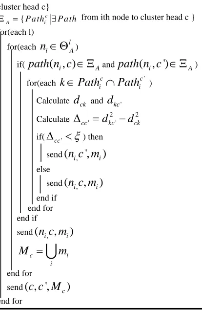
end forFigure 5. Algorithm for RTRA process in Sensor network
The algorithm is to be initialized with all nodes l i
n
in lth cluster in setΘ
lA.The path SetΞ
A contains all the paths from intermediate node i to its respective cluster head and the nearest neighbor’s cluster head. The processRTRA() is executed for all cluster and for each nodes in the respective cluster.The∆
cc'is calculated using equation 5 andis compared with the a value
ξ
as calculated inequation (6). Based on the values of
∆
cc', the packets will be either routed via its own cluster head or the neighbours’ cluster head which is in the path towards the base station as discussed in our proposed approach. However the message aggregation is taken care at each cluster head as presented in the above algorithm.4. MATHEMATICAL ANALYSIS
Let us consider a randomly deployed network with multiple numbers of clusters formed. Each cluster nodes are responsible to elect their respective cluster head. Let us assume in a typical mth cluster formed in a network, there are n-number of sensor nodes and each node sense the physical environment and send the data packet of size pd to the respective
cluster head. In multi-hop communication the shortest distance calculation is being executed with the help of popular Dijkstra's algorithm where the minimum distance is calculated by.
(
,
),
cj cj ck kj
d
=
Min d
d
+
d
∀
k
The energy dissipated by all non-cluster head nodes by sending the pd sized data packet to the cluster
head is given by
2 t
f te d ta d cj j c
p
p
d
ε
ε
≠
Ψ =
+
∑
The energy consumed by the cluster head in receiving n-1 number of pd sized data packets and
sending the aggregated pcd sized data packet to
nearest cluster’s head is given by 2
'
(
1)
r
f
n
p
dε
rε
tep
cdε
tap d
cd ccΨ =
−
+
+
Again in muti-hop communication
'
(
',
');
,
, '
cc cc ck kc
d
=
Min d
d
+
d
∀
k k
≠
c c
So the total energy consumed by all nodes in the mth cluster is
t r
f f f
Ψ = Ψ + Ψ
' ''
d d cd cd
p
ε
p
ε
=
+
(3)Where d'
[
te ta cj2(
1) ]
rj c
d
n
ε
ε ε
ε
≠
=
+
∑
+ −
and'' 2
'
[
]
cd te ta
d
ccε
=
ε
+
ε
.5 dissipation by (n-2) non-cluster head nodes is given by
2
,
(
2)
t
RTRA te d ta d cj j c k
n
p
p
d
ε
ε
≠
Ψ
=
−
+
∑
And the energy consumed by the cluster head to receive the data, aggregates and tranmit to another cluster head c’ is given by
2
' ' '
(
2)
r
RTRA
n
p
dε
rε
tep
cdε
tap d
cd ccΨ
=
−
+
+
Here we need to consider the kth-node’s energy to transmit data to the nearest cluster head instead of sending the sensed data to it’s own cluster head is given by
2 ' k
RTRA
ε
tep
dε
tap d
d kcΨ
=
+
So the total energy consumed by a cluster is given by
t r k
RTRA RTRA RTRA RTRA
Ψ
= Ψ
+ Ψ
+ Ψ
' ' rtra
d d cd cd
p
ε
p
ε
=
+
(4)Where
2 2
' ,
(
1)
(
) (
2)
rtra
d te ta cj kc r
j c k
n
d
d
n
ε
ε
ε
ε
≠
=
− +
∑
+
+ −
So the energy difference between
Ψ
f andRTRA
Ψ
is given byf RTRA
∆Ψ = Ψ − Ψ
In order to
∆Ψ >
0
, we must have2
' ' ' ,
1
[
(
)
]
te
cc cd cc te r
ta
p
d
δ
ε
δε
ε
∆ <
+
−
(5)Where
2 2
' '
cc
d
kcd
ck∆ =
−
, cd' cdd
p
p
p
δ
δ
=
,' cd cd cd
p
p
p
δ
=
−
andδε
te r,=
(
ε
te−
ε
r)
So the
∆
cc' factor of intermediate nodes, which is the difference in distance square between the intermediate node to their own cluster head and to the nearest cluster head(which is on the way towards base station), should be less than the factor2
' ' ,
1
[
(
)
]
te
cd cc te r ta
p
d
ξ
δ
ε
δε
ε
⎡
⎤
=
⎢
+
−
⎥
⎣
⎦
. (6)Based on this value, the intermediate nodes involved in data transmission to base station from cluster head, either transmit the data to its respective cluster head or to the nearest cluster head as mentioned in the algorithm shown section 3.
5. SIMULATION STUDY
In simulation study we have taken the following
parameters to simulate the flooding based routing protocol vs RTRA scheme based routing. The simulation is carried over 100 nodes in 50X50 square unit area (Figure 6(a) ) and 200 nodes in 120X120 square unit area.
1: each node has an initial power of 1 J
2:
ε
r=50nJ/bit means the power dissipated to run the transmitter or receiver circuitry to process 1 bit information3:
ε
ta= 100pJ/ bit / m2 means the power for the transmit amplifier4: base station location (x,y)=(random(),random())
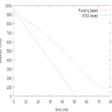
Figure 6(b):Residual Energy Vs Network life time for Flooding and RTRA for 200 nodes over 120X120 square unit area
6 5: Size of the data packets
p
d=1000 bits6:Size of the combined packet
p
cd=
random
()
<
(
n
−
1).1000
and
p
cd'=
random
()
<
(
n
−
2).1000
7: Wireless coverage of each node=7.23 unit
The nodes are distributed randomly. For cluster formation, we have consider the wireless coverage and find the cluster head for flooding based routing protocol.
The residual energy of the nodes vs the network life time is plotted on the graph shown in figure 6(a) and 6(b).In both the scenario we found that our proposed RTRA scheme is providing more life time to the network.
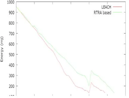
Similary in case of LEACH, we have 80 nodes deployed over 50X50(Figure 7(a)) square unit area and 200 nodes deployed over 75X75 square unit area, and out of which 4 and 10nodes respectively are randomly selected (5% of total nodes) and included in the cluster head list. The simulation depicts that our proposed scheme is providing a better performance in terms of extended life time over LEACH protocol.
6. CONCLUSION
Sensor network constitutes a set of independent Sensor nodes deployed over a specific area to sense and transmit the environmental data. Different flooding and cluster based routing technique are attempted to reduce the energy consumption. However, there is a loss of energy in redundant data transmission in the network. The RTRA scheme is an attempt to reduce this redundant data transmission so as to increase the network life time. Our mathematical observation for the factor
∆
cc' provides the information to the intermediate nodes for taking further decisions for routing. The simulation study provides a better performance for the energy conservation over the flooding based routing and the cluster based LEACH protocol. The frequent cluster head election and control mechanism for traffic load is still a challenge and left for the future scope of the work.I. REFRENCES:
[1] Ian F. Akyildiz, Weilian Su, Yogesh Sankarasubramaniam, and Erdal Cayirci, “A Survey on Sensor Networks,” IEEE Communications Magazine, 40(8) 102-114, August 2002.
[2] M Liu et al. “An Energy aware Routing protocol in Wireless Sensor Networks” Sensors Vol 9, 2009, pages 445- 462.
[3] G. J. Pottie, W. J. Kaiser, “Embedding the Internet: Wireless Integrated Network Sensors,” Communication of ACM, vol.43, no.5, pp. 51-58, May 2000.
[4] C.R. Lin and M. Gerla, “Adaptive Clustering for Mobile Wireless Network,” IEEE J. Select. Area Commun., vol 15, pp. 1265-1275, Sept 1997.
[5] J. H. Ryu, S. Song, and D. H. Cho, “Energy-Conserving Clustering Scheme for Multicasting in Two-tier Mobile Ad-Hoc Networks,” Elec-tron. Lett., vol. 37, pp. 1253- 1255, Sept 2001.
Figure 7(a):Residual Energy Vs Network life time for LEACH and RTRA for 80 nodes over 50X50 square unit area
7 [6] T. C. Hou and T. J. Tsai, “Distributed
Clustering for Multimedia Support in Mobile Multihop Ad Hoc Network,” IEICE Trans. Commun., vol. E84B, pp. 760-770, Apr 2001. [7] Wendi Rabiner Heinzelman, Anantha
Chanfrakasan, and Hari Balakrishnam, “Energy-Efficient Communication Protocol for Wireless Microsensor Networks,” 2000 IEEE The Hawaii International Conference on System Sciences Proceeding, January 2000. [8] Huseyin O. Tan and Ibrahim K. Lu, “Power
Efficient Data Gathering and Aggregation in Wireless Sensor Networks,” ACM SIGMOD, pg. 66-71, 2003.
[9] A Abdolreza et al. “A Neural Network approach for wireless sensor network power management” IEEE International Symposium on Reliable Distributed Systems 2009
[10]Stephanie Lindsey and Cauligi S. Raghavendra, “PEGASIS: Power-Efficient Gathering in Sensor Information Systems,” 2002 IEEE Aerospace Conference Proceeding, March, 2002.
[11]Ossama Younis and Sonia Fahmy, “Distributed Clustering for Scalable, Long-Lived Sensor Networks”, In the 9th Annual International Conference on Mobile Computing and Networking, ACM MobiCom, San Diego, CA, September 2003.
[12]M. Ettus, “System capacity, latency, and power consumption in multihop-routed SS-CDMA wireless network,” Radio and Wireless Conference (RAWCON’ 98) Proceeding, 55-58, August 1998.
[13]T. Shepard, “Channel access scheme for large dense packet radio network,” ACM SIGCOMM Proceeding, 219-230, August 1996.
[14] Ruchuan Wang et al. “A multipath Routing Algorithm based on Traffic prediction in wireless Mesh Network” Communication and Network Vol 1, 2009, pages 82-90.
[15]P. Tillapart, T. Thumthawatworn, P. Pakdeepinit, T. Yeophantong, S. Charoenvikrom and J. Daengdey, “Method for Cluster Heads Selection in Wireless Sensor Network,” Proc. of the 2004 IEEE Aerospace Conference, Big Sky, Montana, USA, 2004.
[16] I.Akyildiz,W.Su, Y.Sankarasubramaniam, E.Cayirci. "A survey on Sensor Networks, IEEE Communications Magazine" [J]. 2002, 40(8): 102-114
[17] Qiangfeng Jiang, Manivannan D. "Routing. Protocols for Sensor Networks"[A]. In:
Consumer Communications and Networking Conference[C]. 2004. 93-98
[18] Wendi Rabiner Heinzelman, Anantha Chandrakasan, Hari Balakrishnan. "Energy-Efficient Communication Protocol for Wireless Microsensor Networks"[A]. In: Proceedings of the 33rd Hawaii International Conference on System Sciences[C].2000.1-10 [19] Stephanie Lindsey, Cauligi Raghavendra.
"Data Gathering Algorithms in Sensor Networks Using Energy Metrics"[J]. IEEE Transactions on Parallel and Distributed Systems, 2002, 13(9): 924-935
[20] Siva D. Muruganat han et al. "A Centralized Energy-Efficient Routing Protocol for Wireless Sensor Networks" IEEE Radio Communications, 2005, 43(3): 8-13
[21] Shi Cheng. "Research and Realization of the Key Iechnology of Wireless Sensor Network". Nan Jing: Southeast University Radio Engineering Department, 2006
[22] Jamal N. Al-Karaki, Raza Ul-Mustafa, Ahmed E. Kamal, "Data Aggregation in Wireless Sensor Networks – Exact and Approximate Algorithms'", Proceedings of IEEE Workshop on High Performance Switching and Routing (HPSR), Phoenix, Arizona, USA 2004, April 18-21, 2004.
[23] Al-Karaki “Routing techniques in wireless sensor networks: a survey” IEEE Wireless Communication Vol 11 issue 6, 2004, pp 6-28.
[24] C. Intanagonwiwat, R. Govindan, and D. Estrin, "Directed diffusion: a scalable and robust communication paradigm for sensor networks," Proceedings of ACM MobiCom '00, Boston, MA, 2000, pp. 56-67.
[25] Yi Feng Zhu et al. “Localization using Neural Network in Wireless Sensor Network” ACM International Conference Mobiware, 2009 [26] Zhihao Guo et al. “Mobile Adhoc Network