Finite Element Modeling for Linear Analysis of
Disc Brake
Mohammed Akram Junaid Shareef
B. Tech. Student B. Tech. Student
Department of Mechanical Engineering Department of Mechanical Engineering Lords Institute of Engineering and Technology Hyderabad
India
Lords Institute of Engineering and Technology Hyderabad India
Md Azher Jaffer Mohammed Asif
B. Tech. Student Assistant Professor
Department of Mechanical Engineering Department of Mechanical Engineering Lords Institute of Engineering and Technology Hyderabad
India
Lords Institute of Engineering and Technology Hyderabad India
Mohammed Iqbal
Assistant Professor
Department of Mechanical Engineering
Lords Institute of Engineering and Technology Hyderabad India
Abstract
The Finite element method in general and commercial finite element analysis software in particular implemented in a computer offers a unified approach for engineering analysis. The focus in this report is on the Linear structural analysis of a disc brake made of Grey Cast Iron and Aluminum material using ANSYS software. The disc is subjected to centrifugal loading by angular velocity and pressure loading by a caliper radically. The significant result for Gray Cast Iron and Aluminum are present and found aluminum has low stress and it has best performance. Finally the report concludes with identification of topics for future works.
Keywords: Disc Brake, CATIA, ANSYS APDL, Structural Analysis, and FEM Analysis
________________________________________________________________________________________________________
I. INTRODUCTION
Disc Brake
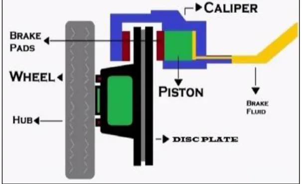
A disk brake consists of a cast iron disk bolted to the wheel hub and a stationary housing called caliper. The caliper is connected to some stationary part of the vehicle like the axle casing as is cast in two parts each part containing a piston. In between each piston and the disk there is a friction pad held in position by retaining pins, spring plates etc. passages are drilled in the caliper for the fluid to enter or leave each housing. The passages are also connected to another one for bleeding.
A hydraulically disc brake comprises one or two opposing pistons each faced with a pad of lining material. When the hydraulic pressure is increased the pads are forced against the rotating metal friction disc, exerting a normal force at each contact. The two normal forces cancel one another axially but cause additive tangential friction forces & retard the motion of the vehicle.
II. DESIGN OF A DISC BRAKE
Disc Brake
For the proposed design of disc brake parameters considered are pressure and angular velocity for different material. Pressure calculation for a disc brake used for a three wheeler car is shown below.
Considerations
Load distribution considered for vehicle is 40:60 from centre of gravity. Average Pedal effort applied by a common man 15kg.
Maximum Speed of vehicle is assumed to be 50kmph.
The calculations are same for both front and rear wheel brakes, up to the brake line after master cylinder. Estimated speed of the vehicle = 50Kmph
Estimated pedal effort of the driver=15Kgs =147.15N Mechanical advantage or pedal ratio=4:1
Force acting on master cylinder = (Estimated pedal effort of the driver*4)=147.15*4=588.6N Diameter of master cylinder=0.75 =19.05mm
Area of master cylinder=285 mm2
Pressure acting on master cylinder = (force*area) = 588.6*285= 2.065N/mm2
The maximum pressure distribution for a disc brake obtained as 2.065Mpa.
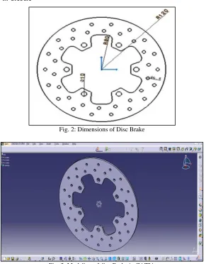
The disc brake selected for analysis is of Bajaj Pulsar 150. Dimensions of the model are mention in figure 2.
Modeling of Disc Brake in CATIA
Fig. 2: Dimensions of Disc Brake
The above shown Fig.3 is model drawn in the CATIA software by using the dimensions of the Pulsar 150 disc brake with correct thickness and Dimensions.
III. FINITE ELEMENT MODEL OF A DISC BRAKE
Geometric Model
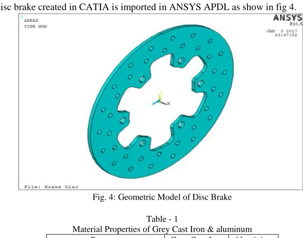
Geometric model of a disc brake created in CATIA is imported in ANSYS APDL as show in fig 4.
Fig. 4: Geometric Model of Disc Brake Table - 1
Material Properties of Grey Cast Iron & aluminum
Property Grey Cast Iron Aluminium
Density (Kg/m3) 7200 2690
Young’s Modulus (G pa) 110 68.9
Poisson’s Ratio 0.28 0.36
Thermal Conductivity (w/m-k) 533 210
Specific Heat (J/kg-k) 506 900
Meshed Model and Boundary Conditions
Discretized model of a disc brake is shown in figure 5. Element type: Solid 186
Number of elements: 1505
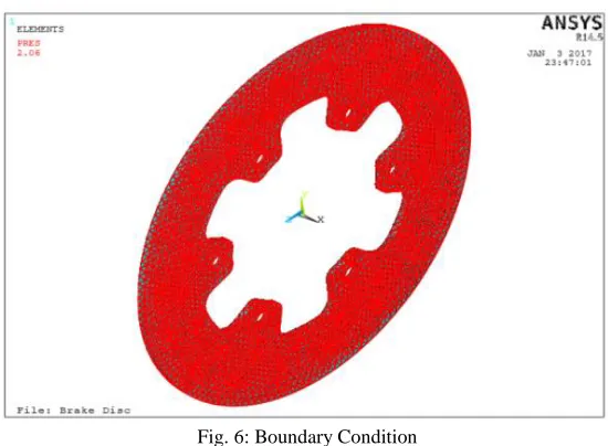
Fig. 6: Boundary Condition
All degrees of freedom for an inner boundary of a disc are fixed. Radial centrifugal force is applied by angular velocity ω = 1104.5 rpm and a Radial pressure of 2.06 Mpa is applied as shown in figure 6.
IV. RESULT ANALYSIS OF A DISC BRAKE
Significant result obtained for disc brake made of Grey Cast Iron & Aluminum is shown in table 2 below. Table - 2
Results of Grey Cast Iron & aluminum
Analysis Materials
Grey Cast Iron Aluminium
Minimum Maximum Minimum Maximum
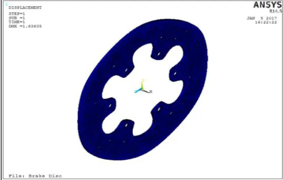
Displacement(mm) 0 3.93223 0 1.63635
Stress (Mpa) 16437.3 22906.6 4622.03 6637.47 Von mises stress (Mpa) 177.609 36740.5 65.2206 9626.07
Stress Analysis of a Grey Cast Iron
The fig. 7 shown below is the displacement diagram of the Grey Cast Iron obtained in the stress analysis performed. It can withstand maximum displacement 3.93223 mm. The fig. 8 shown below is the stress diagram of the Grey Cast Iron obtained in the stress analysis. It can withstand maximum stress 22906.6 Mpa which is performed in ANSYS APDL Software.
Fig. 8: Stress
The fig. 9 shown below is the von mises stress diagram of the Grey Cast Iron obtained in the stress analysis. It can withstand maximum von mises stress is 36740.5 Mpa which is performed in ANSYS APDL Software.
Fig. 9: Von mises stress Stress Analysis of Aluminum
The fig. 10 shown below is the displacement diagram of the aluminum obtained in the stress analysis. It can withstand maximum displacement of 1.63635 mm. The fig. 11 shown below is the stress diagram of the aluminum obtained in the stress analysis. It can withstand maximum stress 6637.47 Mpa which is performed in ANSYS APDL Software
Fig. 11: Stress
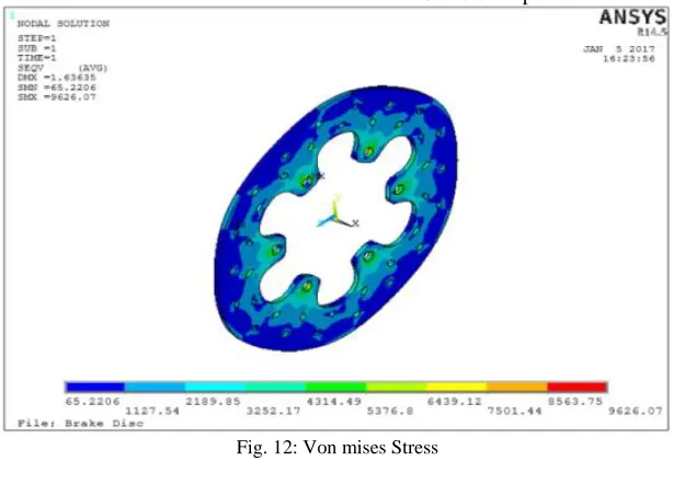
The fig. 12 shown below is the von mises stress diagram of the Aluminum obtained in the stress analysis performed in ANSYS APDL Software. It can withstand a maximum von mises stress of 9626.07 Mpa.
Fig. 12: Von mises Stress V. CONCLUSION
The identified problem is so complex that analytical solutions are not possible. Experimental investigation an prohibitively expensive however finite element modeling using ANSYS Software is demonstrated to provide accurate numerical over a wide range of parameters involved the graphical post processing capabilities exploited to display the results and animate displacement of disc. The significant result of the disc brake is safe based on the strength and rigidity criteria. By comparing the above results obtained from the structural and stress analysis, we can conclude that aluminum has low stress and it has best performance.
VI. FUTURE WORK
The identified problem can further analyze for contact non-linearity, thermal analysis for same or different materials. The significant results can be validated by experimentally.
REFERENCES
[1] Praveena S, Lava Kumar M, SreeKanth Reddy s. ’’Modeling and Structural Analysis of Disc Brake”, International Journal of Innovative Research in Science, Engineering and Technology. vol. 3, Issue 10, October 2014
[2] Manjunath T V, Dr Suresh P M.”Structural and Thermal Analysis of Rotor Disc of Disc Brake”, International Journal of Innovative Research in Science,
Engineering and Technology. vol. 2, Issue 12, December 2013
[3] Kamana.VishnuVardhanChowdary, D.V.S.R.B.M Subhramanyam.”Design and Analysis of Disc Brake”, International Journal of Professional Engineering
[4] Er. N. B. Shinde, Prof. B.R.Borkar.”C.A.D and F.E.M Analysis of Disc Brake System”, International Journal of Engineering and Computer Science.vol. 4, Issue 3, March 2015
[5] Dr.Kripal Singh, Automobile Engineering vol. 1
[6] G. Babukanth& M. VimalTeja. Transient Analysis of Disk Brake By using Ansys Software
[7] BourchateSourabhSivaji, Prof. N.S. Hanamapure and Swapnil S. Kulakarni, “Design, Analysis and Performance Optimization of Disc Brake”,
International Journal of Advanced Engineering Research and Studies, Vol.3, PP. 25-27 2014
[8] Brake Design and Safety, 2nd Ed, Rudolf Limpert, 2010.
[9] ANSYS 14.5 Manual, CATIAV5-6.
[10] V.Chengal Reddy, M.GunaSekhar Reddy, and Dr.G.HarinathGowd “Modeling and Analysis of FSAE car Disc Brake using FEM”, International Journal of