2570
Comparison Of Performance Of Vector Control
Induction Motor Supplied By Zsi With And Without
Pi Controller
Dr. Shyam Sunder Kaushilk, Dr. M. A. Khan, Dr. T. A. Khan, Dr. P.R. Sharma
Abstract : This paper presents the comparison of response of speed, torque and current of Vector Control Induction Motor fed from Z- Source Inverter with and without PI Controller. The speed of 3-phase induction motor using vector control technique can be controlled by converting 3-phase to 2-phase using Clarke transformation. Vector control technique is also known as field orientation control (FOC) method. FOC technique provides proficient and precise regulation of speed of induction motor. The FOC method of an I.M. permits the separately study in which flux and torque segment can be separately regulate. This technique makes the simple study than the per phase corresponding circuit.. The Z-source converter supplied the boosting of input voltage that is not possible in VSI and CSI. Performance of motor is premeditated and compared with and without PI.
————————————————————
1. INTRODUCTION:
The perception of vector control technique has unlocked a latest opportunity through which Induction motors are use very efficiently in comparison of DC motors. Using field orientation (known as also vector control) the dynamic achievement of induction motor is very high. The vector control technique can be implemented to change the induction motor speed for the comprehensive level. In this technique , stator current is indentify the two orthogonal current component, in which one component is used for to control the flux intensity and second component is used to govern the produced torque of the motor. using this technique , we can get quick dynamic reaction, specific speed regulation and speed more than rated. Controllers are designed for closed loop systems for better results. Here PI controller is designed. The gain of the proportional controller is used to make the system stable and for the better transient reaction. To decrease the steady state error, Integral controller is used. The power electronics devices such as Impedance (Z) Source Inverters are use to regulate the speed of field oriented type induction motor. Z-Source Inverter is also used as buck and boost inverter.
2. VECTOR CONTROL INDUCTION MOTOR:
The speed regulation of an induction motor is highly challenging in comparison of the speed regulation a DC motor. An induction motors have not any linear correlation between the current component and produced torque like DC motors. In vector technique, vector transform is done using Clarke and Park transformation in which three phase current is transformed in two current elements, one of them regulates the flux level and other is used for the torque regulation.
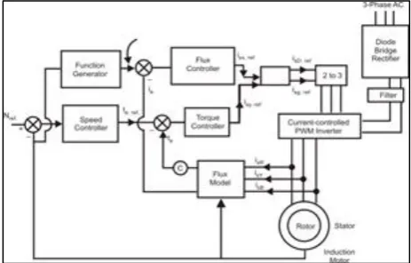
There are many advantage of vector regulation such as a wide range regulation of speed, accurate speed adjustment, quick dynamic reaction and performance over rated speed.The actual rotor speed and the referral speed are fed to summing circuit shown in fig.1. The scheme uses torque regulator/ controller and flux controller. The torque producing stator currents and amplitude of rotor magnetizing current are the output of the flux model. The input to function generator is actual motor speed and its output is the modulus of motor magnetizing current referral. The output of the speed controller gives electro-magnetic torque reference. The scheme uses two current controllers. The two references and are transformed into 3-
stator reference currents. The output of flux controller is stator current reference (i
sx.ref ) and output of torque controller isstator current reference (
i
sy.ref ) the transformation exp( rj
)gives outputi
SD,ref andi
SQ,ref . The 2 to 3 transformation transforms the direct and quadrature axis current reference to 3-
stator current reference. The diode bridge rectifier converts 3-
ac to dc. The filter circuit smoothen the output of rectifier before dc is fed to current controlled pulse width modulated inverter. The reference stator currents adjust the angle of firing of the power electronics devices in the inverter.Fig. 1: 3-
Vector Control Induction Motor______________________________________
Dr. Shyam Sunder Kaushik- Department of EEE, Mewat Engineering College, Nuh,
Dr. M.A. Khan - Prof., Section of EE , JMI, Central University, New Delhi ,
Dr. T.A. Khan - Department of EEE, Mewat Engineering College, Nuh,
The rotating synchronous is produced with the stator flux due to relative movement between the stationary referral frame and referral frame. The objective of a referral frame is to convert in to a quantity which is sinusoidal in one referral frame and referral frame revolving at similar frequency.
3.
PROPORTIONAL
-
INTEGRAL
(PI)
CONTROLLER:
At present, the Proportional-Integral Controllers have simple composition and design and less price. So that in industrial application, PI Controller is mostly used. PI controller will prevent no electively oscillations and also eliminate steady state error. PI controllers are used on industry , when there is no problem regarding speed.
A Proportional -Integral Controller is used for the following conditions :
1 When the system has not required fast response 2 When during the action of process, the system has
large disturbances and noise
3 When the system occur only one energy storage during action (capacitive or inductive)
4 When the system occur huge transport delays in the process.
Fig. 2: Block diagram of Proportional -Integral Controller
So, we will use PI Controller for above given conditions. Initial in PI controller the proportional gain is firstly used and that time the integral gain is kept fixed. In fig. 2, Integral controller is used for error compensation , then result response is vary with the integration of the desired signal. For this compensation, a controller is developed whose output response have two gains, one gain is proportional to the desired signal and the other gain proportional to its integration. Such type of controller is known as Proportional-Integral controller.
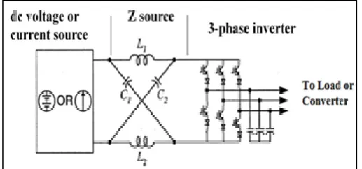
converter, for given specific characteristic which are not consist by the conventional voltage source and current source inverters. The conventional inverters have six switching states in the bridge but impedance source inverter has seven licit switching states.
Fig. 3: Block Diagram of ZSI
In the inverter bridge, both the IGBT devices of the same phase are shorted on the output terminal i.e. both IGBT are gated on , shoot-through zero state condition occur. In conventional VSI, the shoot-through zero state is prohibited. The shoot-through zero state condition is occur in impedance source network. The buck-boost feature are not available in conventional inverters. Due to shoot through zero state, these feature are occur in the Z-Source Inverter.
5. CIRCUIT AND SIMULATION:
The dc supply is converted in to 3-
output voltage by regulating the switches of impedance inverter bridge than3-
output is linked to VCIM. The DC source voltage is grows or reduced to the necessary level of voltage with the help of the latest design of the impedance fed inverter bridge. The output dc voltage can be expand to large magnitude by increasing the inductance in the inverter topology. Similarly the output dc voltage is reduced by growing the capacitance value in the topology, so buck/boost in voltage is obtained. Without any loss in the switches the impedance fed inverter permits the both IGBT switches in the same phase leg to be on at similar time. This avoid the existence of any short circuit arrangement. By regulating the duty cycle of the rush of current condition of impedance fed inverter, buck/boost behaviour becomes better. The different element with the given values areemployed in the arrangement such as Inductors L1 = L2 =
160mH; Capacitors C 1= 1000 μF and C2 =470μF. The PI
controller is employed with this arrangement to compare
the achievement of the 3-
vector control induction motor2572
Parameters Symbol Values (with IS
Units)
Resistance of Stator Rs 0.02
Resistance of Rotor Rr 0.03
Magnetizing Inductance Lm 4.0
Stator Leakage
Inductance Ls 0.15
Leakage Inductance of
Rotor Lr 0.15
Moment of Inertia J 1.762
Viscous Friction
Coefficient B 0.02
Table 1:-Some Useful Parameters of Induction Motor
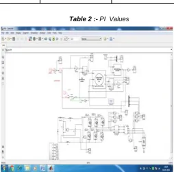
Controller Proportional Integral K 0.16567 0.02787
Table 2 :- PI Values
Fig.4 :Simulation of the Vector Control Induction Motor supplied by ZSI without any Controller
Fig.5: Simulation of the Vector Control Induction Motor fed from ZSI with PI Controller
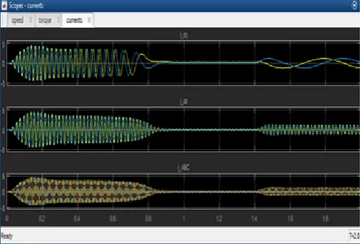
Fig. 6 and Fig. 7 display the simulation response for speed of Vector Control Induction Motor which is fed by Z-Source Inverter without any controller and with PI Controller respectively. Similarly Fig 8 and Fig. 9 shows the simulation response for output torque of Vector Control Induction Motor supplied by Z-Source Inverter without any controller and using PI Controller.
Fig.7: Speed of Vector Control Induction Motor Fed from ZSI with PI Controller
Fig. 8: Output Torque of Vector Control Induction Motor Fed by ZSI without any Controller
Fig. 9:Output Torque of Vector Control Induction Motor Fed by ZSI with PI Controller
Fig. 10: Output Current of Vector Control Induction Motor Fed from ZSI without any Controller
Fig.11: Output Current of PI Controller Based Vector Control Induction Motor Fed by Z-Source Inverter
6. CONCLUSION:
This paper shows the performance of vector control I.M supplied by ZSI without and with PI Controller. The advantage of circuit has been given below :
1 The same voltage boost can be get by replacing high value of capacitor with low value of capacitor and size and cost will be diminished.
2 The inrush current in the inverter bridge can be cover up using ZSI.
3 The response of the induction motor speed can be increased with the help of PI controller.
2574
Electrical Engineering, ISSN:-2347-6982, Vol. -5, Issue-8,pp- 70-78, August 2017.
2 Shyam Sunder Kaushik and M.A. Khan, "Implementation of Fuzzy Controller on Vector Control Induction Motor fed by Z-Source Inverter” International Journal of Industrial Electronics & Electrical Engineering, ISSN:-2347-6982, Vol. -5, Issue-5,pp- 50-55, May 2017.
3 Shyam Sunder Kaushik, Prof. J.S.Khan and D.K. Sharma,"Implementation of PID on Vector Control Induction Motor fed by Z-Source Inverter” International Journal of Advanced Engineering Research and Technology, ISSN:-2348-8190, Vol.-3,
Issue-7,pp- 265-270, July 2015.
4 Shyam Sunder Kaushik,Prof. J.S.Khan and D.K. Sharma,"Analysis and Simulation for Speed Control of an Induction Motor with Z-Source Inverter” International Journal of Scientific Research Engineering and Technology, ISSN:-2278-0882, Vol-4, Issue-7,pp- 793-798, July 2015.
5