IOSR Journal of Engineering (IOSRJEN)
e-ISSN: 2250-3021, p-ISSN: 2278-8719Vol. 3, Issue 5(May. 2013), ||V3 || PP 39-45
Transient Stability Analysis of Multimachine System Using
Statcom
Sujith. S, T.Nandagopal
Dept. of Electrical & Electronics Engineering Paavai Engineering College Salem, India Asst. Professor, Dept. of EEE Paavai Engineering College Salem, India
Abstract: The modern power system transmission networks are becoming increasingly stressed. This is because of the growing demand and restrictions on building new lines. Transient instability is because of short time faults, switching on and off of the loads etc. so that there is an unbalance between the input power(Pm) from the turbine and the electrical power(Pe) output to the electrical network. The static synchronous compensator (STATCOM) can increase transmission capacity, damping low frequency oscillation and enhancing the transient stability. The power system analysis toolbox (PSAT) software package is used for the simulation of the test system. IEEE14 bus system is used as the multimachine system. In this paper three cases are considered i) steady state system ii) faulty system iii) transient stability enhanced system(with STATCOM). The study demonstrates that STATCOM can enhance the transient stability of multimachine system.
IndexTerms: STATCOM, PSAT, transient stability, multimachine system
I. INTRODUCTION
The power system is a highly nonlinear system that operates in a constantly changing environment. When a transient disturbance occurs, the stability of the power system depends on the nature of the disturbance as well as the initial operating condition. By the development and use of FACTS equipment it becomes possible to enhance the power system transient stability.
The STATCOM plays an important role in generating a balance three phase voltage whose magnitude and phase can be adjusted by using semiconductor switching devices. The STATCOM mainly consists of a voltage source inverter with a dc capacitor, coupling transformer, control circuit and signal generator. The response time of STATCOM is extremely faster than of synchronous condenser. This fastness in response is very helpful in enhancing the transient stability, enhancing voltage support, and to damp low frequency oscillations for the power systems [1]. Because of increase in power demand, power system networks are becoming larger and more interconnected. As a result, transient instability becomes more serious. Because of the transient instability, the network collapse may occur with economic losses and severe power grid damages that may lead to overall blackout. The STATCOM along with PI controller is used to improve the transient stability [2]. Transient instability is more in the case of multimachine system than in the case of single machine system. The power system stability improvement by the FACTS devices is well known, in literature [3]. There are certain assumptions to reduce the complexity of transient stability analysis. Each synchronous machine is represented by a constant voltage source behind the direct axis transient reactance. This representation neglects the effects of saliency and assumes constant flux linkages. The actions of the governor are neglected and the input powers are assumed to remain constant during the entire period of simulation. Using the prefault bus voltages, all loads are converted to equivalent admittance to ground and are assumed to remain constant. Damping and asynchronous powers are ignored. The mechanical rotor angle of each machine coincides with the angle of the voltage behind the machine reactance. Machine belonging to the same station swing together and are said to be coherent. A group of coherent machines are represented by one equivalent machine. IEEE-14 bus system with loads having constant impedance and all generators with constant excitation and constant mechanical input power. Five synchronous machine with IEEE type1 excitation three of which are synchronous compensators. Generator1 is taken as reference generator [4]. Super conducting magnetic energy storage (SMES) can be connected at the generator terminal for single machine infinite bus system to improve the transient stability [5].
Power system analysis tool box (PSAT) software is used for the simulation of the result. The main features of PSAT are power flow, continuation power flow, optimal power flow, small signal stability analysis, time domain simulation, phasor measurement unit placement, complete graphical user interface, CAD for network design, user define models, command line usage etc.[6].
II. STATCOM UNIT AND MODELING
The STATCOM is a shunt connected reactive power compensation device that is capable of generating or absorbing the reactive power. The three main components of STATCOM are voltage source converter with a capacitor in the DC side, coupling transformer and the control system. If the voltage at the STATCOM terminal is higher than the system voltage, then the reactive power will be injected from the STATCOM to the system. When the voltage at the STATCOM is less than the AC voltage the reactive power will be absorbed by the STATCOM.
Under normal operating condition, both the system voltage and the STATCOM voltage are equal and there will be no power exchange between the STATCOM and the system.
The STATCOM equations in d-q reference frame is given as following [2]:
𝑑𝑖𝑠𝑑
𝑑𝑡 = −
𝑅𝑠𝑤𝑜
𝑋𝑠 𝑖𝑠𝑑 − 𝑤𝑜𝑖𝑠𝑞 + 𝑤𝑜
𝑋𝑠 𝑉1𝑑 − 𝑉2𝑑 (1) 𝑑𝑖𝑠𝑞
𝑑𝑡 = 𝑤𝑜isd− 𝑅𝑠𝑤𝑜
𝑋𝑠 isq+
𝑤𝑜
𝑋𝑠 𝑉1𝑑 − 𝑉2𝑑 (2) 𝑑𝑣𝑑𝑐
𝑑𝑡 = − 𝑃𝑠
𝐶𝑣𝑑𝑐 − 𝑉𝑑𝑐
𝑅𝑐𝐶 (3)
Where isd and isq are the d-axis and q-axis STSCOM current components, Rs,Xs are the resistance and leaking reactance of the coupling transformer. Vdc is the capacitor voltage, Rc is the leakage resistance parallel with the capacitor, wo is the angular speed.
By varying the inverter firing angle α the reactive power variation can be instantly achieved and hence improving the transient stability.
III. SINGLELINEDIAGRAMOFIEEE14BUSSYSTEM
Fig. 2.Single line diagram of IEEE 14 bus system
The best location for the reactive power compensation of transient stability margin is the weakest bus of the system. The bus nearest to experiencing a voltage collapse or the fault occurs is defined as the weakest bus.
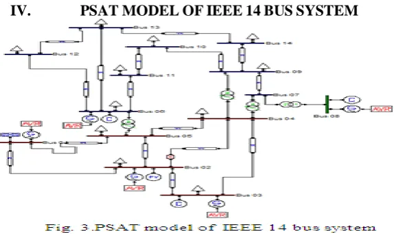
IV. PSATMODELOFIEEE14BUSSYSTEM
This is the steady state condition that is the prefault condition. Transient stability is more in this condition. From Fig. 3. the IEEE 14-bus network built using the PSAT Simulink library. Once defined in the Simulink model, one can load the network in PSAT and solve the power flow. Power flow results can be displayed in a GUI and exported to a file in several formats including Excel and LaTeX. PSAT also allows displaying bus voltages and power flows within the Simulink model of the currently loaded system. Notice that PSAT uses vectorized computations and sparse matrix functions provided by MATLAB, so that computation times increase slowly as the network size increase. Net power flow computation times for a variety of tests network, with different solvers, namely NR method and fast decoupled power flows. Result was obtained using the command line version of PSAT.
V. BUSDATAFORIEEE14BUSSYSTEM
The power flow analysis is carried out for the IEEE 14 bus system using Newton-Raphson method using PSAT software. Load flow study in power system is the steady state solution of the power system network. The main advantage of NR method is its reliability towards convergence.
The NR method for power flow computation using PSAT software is as follows: Newton-Raphson Method for Power Flow Computation
Datafile"C:\Users\Sujith\Documents\MATLAB\psat\tests\d_014_dyn(mdl)" Writing file "fm_call" ...
PF solver: Newton-Raphson method Single slack bus model
Iteration = 1 Maximum Convergency Error = 0.34209 Iteration = 2 Maximum Convergency Error = 0.010326 Iteration = 3 Maximum Convergency Error = 0.00012686 Iteration = 4 Maximum Convergency Error = 2.1277e-008 Initialization of Synchronous Machines completed.
Initialization of Automatic Voltage Regulators completed. Power Flow completed in 0.047 s
From the above iterations it is clear that the maximum convergence error is 2.1277e-008. Voltage time, rotor angle and time graph are plotted for IEEE 14 bus system using PSAT software.
VII. FAULT CONDITION
To create a transient instability a single line to ground fault is introduced between Bus01 and Bus05. A single line to ground fault is introduced in Bus1. The introduced fault is a transient fault. The relative frequency of occurrence of single line to ground fault is 70%. So the introduced fault is single line to ground fault. The introduced fault time is 0.11sec. Fault clearing time is 0.250sec.
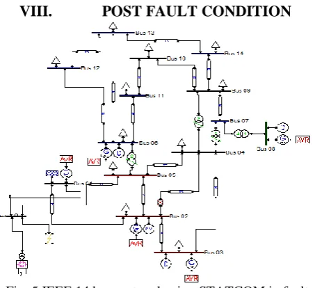
VIII. POST FAULT CONDITION
Fig. 5.IEEE 14 bus system having STATCOM in faulty bus
STATCOM is introduced in the Bus1. Since the fault is introduced in the Bus1 the transient instability will be more in Bus1. The enhancement of transient stability can be verified my means of the power flow analysis and from the graphs.
The NR method for power flow computation using PSAT software is as follows: PF solver: Newton-Raphson method
Iteration = 1 Maximum Convergency Error = 0.55787 Iteration = 2 Maximum Convergency Error = 0.030277 Iteration = 3 Maximum Convergency Error = 0.00064373 Iteration = 4 Maximum Convergency Error = 3.8554e-007 Initialization of Synchronous Machines completed.
Warning: AVR #5 at bus #Bus 06 Vr1 is under its min limit. Automatic Voltage Regulators cannot be properly initialized.
Warning: STATCOM #1 at bus <Bus2>: no PV generator found at the bus. Warning: STATCOM #1 at bus <Bus2>: Ish is under its min limit.
Initialization of STATCOMs completed. Power Flow completed in 0.047 s
The error is less than that of IEEE 14 bus system having single line to ground fault in it. The maximum convergence error is 3.8554e-007.
IX. SIMULATION
The output of the generators during prefault, fault and post fault conditions is plotted using PSAT software.
From the Fig. 6.the voltage time waveform of a steady state system is obtained. From the Fig. 7.the swing curve the value of δ initially high then decreases which makes the system stable. From the swing curve the transient stability can be identify. If the value continuously goes straight then it is an unstable system that is instability is more.
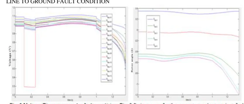
ii) LINE TO GROUND FAULT CONDITION
From the Fig. 8.there is a sudden dip in the voltage time curve of Bus1. The single line to ground fault arises at 0.15s and since the fault is transient fault the fault exists only for 0.23s. From the Fig. 9.there exists a rotor angle instability in the Generator1. During the fault the transmitted electrical power decreases significantly while the mechanical input power to the generator remains constant, as a result the generator continuously accelerate and the rotor angle instability can be seen in Fig. 9. When the fault is cleared at 0.23 s the speed is continuously increasing and the system is not able to regain the stability due to the lack of damping. During the fault, the generator terminal experience a voltage sag of more than 90% without the STATCOM as shown in Fig. 8. This voltage is not recovered after the fault is clearance due to lack of reactive power support. The transient instability is more in the case of faulty condition. This instability can be overcome by introducing STATCOM in the unstable bus.
X. X CONCLUSION
The simulation results using PSAT software shows clearly the impact of STATCOM in enhancing the transient stability of multimachine system. In this paper the transient stability enhancement of multimachine system is analyzed. The stability has determined by plotting the voltage time curve and the swing curves. The single line to ground fault is cleared by introducing the STATCOM in the faulty system.
It is therefore recommended that the power system engineers must do proper care in enhancing the transient stability. Thus it is concluded that STATCOM helps in enhancing the transient stability of multimachine system.
REFERENCES
[1]. S.H.Hosseini & A.Ajami, “Transient stability enhancement of AC transmission system using STATCOM” proceedings of IEEE TENCON02. Vol. 33, No. 2, March 2002, pp. 1809-1812.
[2]. A.F.Abdou,A.Abu-Siada and H.R.Pota, “Application of a STATCOM for Damping Synchronous Oscillations and Transient Stability” Proceedings of the Canadian Conference on Electrical and Computer Engineering (CCECE) 1998, pp. 477-480.
[3]. Sadi Amara and Haji Abdallah Hsan, “Power system stability improvement by FACTS devices: a comparison between STATCOM,SSC and UPFC” First International Conference on Renewable Energies 2012,pp.360-364.
[4]. Galu Papy Yuma and Kanzumba Kusakana,”Damping of oscillations of the IEEE 14 bus Power System by SVC with STATCOM” Proceedings of 5th
international conference on AC and DC Power Transmission-IEEE Conference Publication 2012.
[5]. Rintu Khanna, Gurnam Singh and T.K.Nagsarkar, “Power System Stability Enhancement with SMES” IEEE Transactions on Power Apparatus and Systems,Vol.2,2012 IEEE.
[6]. P.K.Iyambo and R.Tzoneva, “Transient Stability Analysis of the IEEE 14-Bus Electrical Power System” In Proc.of , NAPS-2000,May12,2012 pp.1-8 IEEE.