Volume-5 Issue-1
International Journal of Intellectual Advancements and
Research in Engineering Computations
ISSN:2348-2079
Modeling and simulation of level control phenomena in a non-linear system
S.Pooja,
PG Scholar, Dept. of EIE Kongu Engineering College
Perundurai, Erode [email protected]
Dr.S.Vijayachitra,
Professor, Dept. of EIE Kongu Engineering College
Perundurai, Erode [email protected]
Abstract-In recent years, model based controllers have proved a successful control strategy for analysing the performance of non-linear systems. The present study focuses on the conical tank system. If compared to the cylindrical tank system, the conical tank system has highly non-linear due to variation in cross sectional area with change in shape. In many process industries like Chemical industries, Petroleum industries, Paper industries, Water treatment plants, Fermentation industries etc.., it is preferred to have conical tank system because, it can offer more advantages than cylindrical tank system and spherical tank system such as minimum product losses, inexpensive etc... In the proposed work, modeling strategy is intended to provide a simple description of a peculiar structure of the non-interacting conical tank system. A model based controller of Internal Model Controller (IMC) is designed which can control the liquid level in the system at desired setpoint. Consequently, they can provide better output performance which can be measured in terms of overshoot, setpoint tracking and settling time when compared to conventional PID controller.
Keywords: Conical tank system, Model based controller, Process Modeling, PID controller, Internal Model Control
I. INTRODUCTION
Conical tank system is a nonlinear system which consists of broad area at the upper end and becomes narrow at the lower end. In the application of process industries, controlling the physical variables such as flow, level, temperature and pressure is a challenging one. Mostly in level based control process, the tank system may be in the form of cylindrical type and conical type. In cylindrical type tanks, there will not be better drainage. To achieve complete drainage of the liquid, conical shaped tank is preferred in process industries. In process industries, the liquids will be processed in conical tanks for chemical storage, concrete mixing, food processing and waste product draining etc...
To control the level in the tank, it is found difficult, due to its nonlinear property of conical tank system which has continuously varying the area of the tank at each dimension. Hence, it is required to provide a sophisticated method to control the level in the conical tank. This paper deals with the non-interacting type conical tank system. The modeling of the non- interacting conical tank system is to be designed first and then model based controller of IMC is used to analyse the system behaviour in the environment of development and testing by using MATLAB.
In [1], P. Aravind et al. proposed a nonlinear model of conical tank level control system and real time system designs are analysed and their implementation of the PI controller is done by direct synthesis method and skogestad method. In [2], D. Hariharan et al. designed the mathematical modeling of single conical tank, two conical tanks of non-interacting type system and two conical tanks of interacting type system is designed and also obtained the responses of the process.
In [4], J. Arputha Vijay Selvi et al. proposed conventional PID and IMC, are considered and are comparatively analysed using standard robustness measures for stability and performance. In [5], Jeffrey E. Arbogast et al. implemented the novel IMC correlations calculate a filter time constant based upon the modal of the process and the user’s choice for the closed loop time constant. The set point tracking and disturbance rejection performance of the IMC tunings are also demonstrated.
analysed by adding the disturbance to the process and output is retained to the setpoint of the process.
In [8], S. Vadivalagi et al. presented the parameters are optimally and robustly adjusted with respect to the system dynamics. In [9], P. Suganthini et al. proposed the IMC controller which proven that the IMC control method is to enhance the stability of the conical tank system.
In [10], T. Pushpaveni et al. designed the Model Predictive Controller(MPC) to track the setpoint changes and load disturbances which control the level and also to enhance the stability in the conical tank system.
This paper endeavours to provide an overview about to control the liquid level in non-interacting conical tank system using Conventional PID and IMC controller. Section II provides a brief description about conical tank system. Section III moves to focus on mathematical modeling of non-interacting conical tank system. Design and selection of PID
controller parameters are discussed in Section IV. In Section V, IMC controller is designed and comparative
simulation results are also presented. Finally, conclusions are drawn in Section VI.
II. PROCESS DESCRIPTION
A. Description of the Conical Tank System
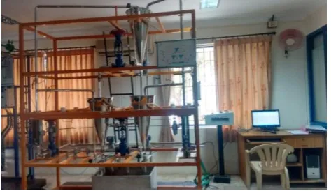
The experimental setup of conical tank system is shown in Fig. 1 which is designed by interacting and non-interacting type. The system consists of conical tank, reservoir tank, centrifugal pump, differential pressure transmitter (DPT), air regulator, (I/V) converter, electro pneumatic converter (I/P), LabVIEW card.
Fig. 1 Experimental Setup of Conical Tank System
The level in the tank which is measured by using DPT and the signals can be transmitted in the form of (4-20mA) to the (I/V) converter. The LabVIEW card was interfaced to the Personal Computer (PC). After, designed the controllers in the PC, the control signals are transmitted in the form of current signal (4-20mA) to the (I/P) converter then it passes the air signal to the pneumatic control valve. The control valve which is actuated by this signal to produce the required flow of water into the conical tank and outflow is considered as constant.
There is a continuous flow of water in and out of the conical tank.
B. Process Model of conical Tank System
The structure of non- interacting conical tank system is shown in Fig. 2 in which tank-1 inlet Fin1 being the inflow
rate(m3/s) and outlet is Fin2 which is the fluid level(m).
H1 represents the total height of the tank 1and h1 represents the
level of the tank-1. Similarly, the inlet flow of tank-2 represents the Fin2 and outlet flow of the tank-2 represents the
Fin3. H2 represents the total height of the tank-2 and h2
represents the level of the tank-2. MV1, MV3, MV21 represents rotameter.
Fig. 2 Process Model of Non-interacting Conical Tank System
III. MATHEMATICAL MODELING
Using mass balance equation, the mathematical modeling for two tank non-interacting conical tank system is derived below,
The transfer function of the two tank non-interacting conical tank is given by,
1 1
2 1
1
1 2
s s
kk s
U s Y
(1)To obtain the transfer function of the proposed system, by considering the following specifications as follows,
i) R = Top radius of the conical tank = 17cm
ii) H = Maximum height of tank 1 and tank 2 = 70 cm
iii) Fin1 & Fin2 = Maximum inflow to tank 1and tank 2
= 500 LPH
iv) Cv1 & Cv2 = Valve coefficient of MV1 & MV2 = 14(1 inch)
v) Cv12 = Valve coefficient of MV12 = 11(3/4 inch)
Hence, the transfer function of two conical tank non- interacting system is given by,
Rate of accumulation of mass in the tank
=
Mass of inlet flow rate
-
626.5352 50.2932 10207 . 0 2 1 2 s s s U s Y (2)
A. Real Time Data Logging
The two conical tank non- interacting system input-output data are required which are collected in real time setup of conical tank system is shown in Fig. 2. From this, the level of the tank1 represented as h1 and the level of the tank 2
represented as h2.The various input-output data are collected
from two conical tank non- interacting system are presented in Table I.
Table I. Input-Output Data Collection
Fin 1 = 100 LPH Fin 2 = 62 LPH Fin2 (LPH) h1 (cm) h2 (cm) Fin1 (LPH) h1 (cm) h2 (cm) 200 18 11 100 25 25 250 23 15 150 20 33 300 30 19 200 12 38 .. .. .. .. .. .. .. .. .. .. .. .. 400 40 25 106 0 46
IV. CONVENTIONAL PID CONTROLLER Conventional PID controllers have been widely used in many process control industries. It has a simple structure and acceptable performance. The transfer function of two conical tank non-interacting system has derived, the controller has to be designed for maintaining the system to the desired set point. This can be obtained by properly selecting the tuning parameters which are KP, TI and TD for a conventional PID
controller. The required gain values of PID controller are obtained by using cohen and coon tuning recommentations. Fig 3 shows the response of Conventional PID controller and the tuning parameters are K p = 376.693, K I = 0.0445 and
K D = 5.2932.
Fig.3 Response of Conventional PID Controller
V. INTERNAL MODEL CONTROLLER
Internal model control is model based controller. The Fig. 4 shows the IMC structure which makes use of a process model to identify the effect of immeasurable disturbance on the process output and then counteracts that effect.
Internal model controller is based on the control system, which holds some model of the process to be controlled then a faultless control can be attained in the conical tank system.
Fig. 4 Block diagram of IMC
In this diagram,
p
G is the process plant, * p
G is the model of the process, Qc, is an controller, to control the process,
d
* is an unknown disturbance affecting the system. The manipulated input u is introduced to both the process and its model. The process output, Y is compared with the output of the model, resulting in a signal d*.IMC is designed for the conical tank system by the transfer function given in equation (3)
1 2932 . 50 5352 . 626 0207 . 0 ) ( 2 s s s Gp (3) From this, IMC is designed by the given equation (4)
) ( ) ( )
(s Q sG s
GIMC c f
(4) where,
) (s
Qc = inverse of the model of the process )
(s
Gf = low pass filter
The transfer function of the low pass filter is given below
1 1 )
(
2
1
s s s Gf
(5)
The model is an exact representation of the process, ).
( ) (s G s
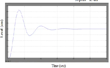
Fig. 5 Response of Internal Model Controller
The servo response was also obtained for changing set point profile from 25cm to 50 cm without an influence of any external disturbance. Fig. 6 shows the set point tracking for different changing set points of level in tank 2.
Fig. 6 Response of Servo Operation for IMC
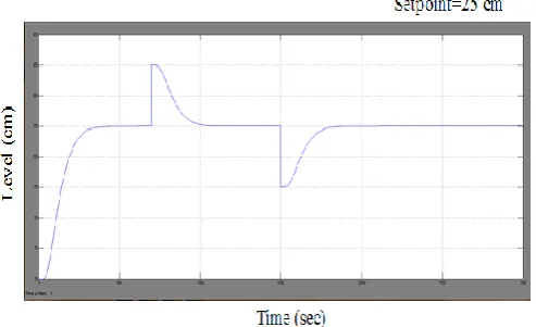
A sudden disturbance is given by pouring water into tank 2 while the system becomes stable. The leakage of some amount of water from tank 2 is considered as the error introduced to the system. Fig.7 shows the regulatory response obtained at different set points from 25cm to 42cm by introducing disturbance and the error in the tank2.
Fig. 7 Response of Regulatory Operation for IMC
After the tuning procedures are done through the controllers of conventional PID and IMC control techniques, the responses are analysed to a step input. The responses of conventional PID and IMC controllers are compared, which is shown in Fig. 8.
Fig. 8 Comparative Responses for PID and IMC
In the time domain, specifications for a control system design involve certain requirements associated with the time response of the system. A comparative study of their performance has been in the Table II.
Table II. Comparison of Time Domain parameters
S.NO
TIME DOMAIN
PARAMETERS PID IMC
1. Settling Time (sec) 150 52
2. Overshoot (%) 41 0
The requirements are often expressed in terms of the standard quantities on the rise time, settling time, overshoot, peak time, and steady state error of a step response. From the above observation, IMC controller shows the better settling time and there is no overshoot in the two conical tank non- interacting system.
VI. CONCLUSION
In this proposed work, two conical tank of non-interacting type is taken as a non-linear system. For which, a conventional PID controller is designed to achieve the level control in conical tank system. But due to the unsatisfactory performance of the conventional PID controller, a model based controller of IMC is designed and placed in the forward path of the system. From the comparative results, it is found that the settling time and the overshoot of conventional PID controller such as 150 sec and 41 % are higher than the IMC controller. Simulated studies have also proved that IMC Control technique has good servo tracking and disturbance rejection capability.
VII. REFERENCES
[1]. P.Aravind, M.Valluvan, S.Ranganathan (2013), “Modeling and Simulation of Non Linear Tank”, International Journal of Advanced Research in Electrical, Electronics and Instrumentation Engineering, Vol. 2( 2), pp. 842-849.
[3]. George Stephanopoulos (1984), “Chemical Process Control”, Prentice-Hall Publication, New Jersey, Eastern Economy Edition.
[4]. Arputha Vijayaselvi J, Rathakirushnan TK, Sundaram S. (2007) “Performance assessment of PID and IMC tuning methods for a mixing process with time delay”, ISA Transaction. Vol.47(3), pp. 391-97.
[5]. Jeffrey E. Arbogast, Douglas J. Cooper (2007), “Extension of IMC tuning correlation for non-self regulating (integrating) process”, ISA Transactions, Vol.46(3), pp. 303-311.
[6]. D.Angeline Vijula, K.Vivetha, K.Gandhimathi and T. Praveena (2014), “Model based Controller Design for Conical Tank System”, International Journal of Computer Applications, Vol. 85(12), pp. 8-11.
[7]. E. Kesavan, Agalya, P. Palpandian and S. Manoharan, (2016), “Performance Analysis and Comparison of Different Tuning Strategies of PI Controller in Conical Tank”, Indian Journal of Science and Technology, Vol. 9(11), pp. 1-6.
[8]. S. Vadivazhagi and N. Jaya,(2015), “Control of Two Tank Conical Interacting Level System using Relay Auto Tuning” ,Indian Journal of Science and Technology, Vol. 8(12), pp. 1-6.
[9]. P. Suganthini, P. Aravind, and S. M. Girirajkumar,(2014), “Design of Model Based Controller for a Non-Linear Process”, International Journal of Computer Applications, Vol. 85(12), pp. 3253-3256.