IJEDR1802044
International Journal of Engineering Development and Research (
www.ijedr.org
)
248
Design of Bicycle Handle using Ergonomic Aspects
A Review
1
Pradeep M. Ingole,
2Dr. Nilesh S. Pohokar,
3Dr. Atul B. Borade
1Associate Professor,2Assistant Professor,3Professor 1Department of Mechanical Engineering,
1,2Prof. Ram Meghe Institute of Technology and Research Badnera, Amravati, Maharashtra,India 3Jawarharlal Darda Insitite of Engineering and Technology, Yevatmal, Maharashtra, India
_____________________________________________________________________________________________________
Abstract— The name is also called a bike of rural people. Bicycles have evolved significantly over the past decades in
pace with technological advancement. However the comfort of cyclists has not much attempted in many designs. Although ample research has been reported on comfort for other means of transportation, cyclist’s perception of comfort has received scant attention in the scientific literature. This paper discusses the ergonomic aspects that can be incorporated in the design of a bicycle handle. The first step is to determine which factors contribute to comfort when riding a bicycle which results in human performance and fatigue. It has been found out by means of a survey with enthusiast cyclists that comfort is influenced by factors related to the cyclist (driver position, handle adjustments, body parts). This paper classified into three parts, in the first part the ergonomic aspects of bicycle handle, in second the factors responsible for fatigue and in the third analysis for the comfort positions. The most of the researchers presents there work in change seating position whereas this work focuses on the comfort position of bicycle handles.
IndexTerms— Bicycle, Ergonomic study, comfort positions, Fatique.
_____________________________________________________________________________________________________
I.INTRODUCTION
A bicycle or bike is a vehicle composed of two wheels held in a frame one behind the other, propelled by pedals and steered with handlebars attached to the front wheel. Karl von Drais of Paris invented the first bicycle in 1817[56,57]. The Draisienne was a steerable bicycle[30]. It was almost entirely made of wood, had no pedals, and was propelled down the street by riders who would push their feet against the ground. The record speed was 15 km/h. [1] Ergonomics is the investigation about humans and work. especially when optimizing the physical contact between humans and engine [100].
Even in this 21st century, the century of modern machines and fast moving automobiles, the cycle has its own identity and importance[54]. Apart from the fact that it is eco-friendly and economical, helping the riders to keep fit and healthy[89]. There have been several changes in the bicycle design since its inception, many attempts were made over the years[78]. Today various designs and styles of bicycles have been introduced like sport/road bicycles, mountain bicycles, BMX (Bicycle Motocross) cycles etc. Throughout the world bicycles are used by school students, University students to go around in the University campus, proletariats to go to work and old aged people for physiotherapy[55]. It is important to keep in mind the widespread use of bicycles necessitates the design should match the anthropometric data to be ergonomic[84]. It is also important to keep a check on the production costs of the bicycle because it is generally considered an economic product[4]. It is crucial to ensure a good industrial design procedure for the bicycle while making substantial ergonomic changes in the conceptual design[60]. An effort has been made to identify the possible inconvenience caused to the rider and propose a design to solve the problems reducing the inconvenience of the bicycle riders [99]. A concise overview of relevant studies is presented here[73]. According to three distinct areas contribute to comfort when riding a bicycle i.e.; environmental, mechanical and biomechanical factors, and physiological factors [96].
A bicycle is a pedal driven , human-powered vechicle with two wheels attached to a frame, one behind the other. Bicycle is a mode of transportation. It is a good exercise machine[74]. It can move around or get good exercise. Complety it is a good source of excercise. Comfort when riding a bicycle can be identified through a number of key elements such as seats, handles, paddle and bicycle frame design[9,10]. More specifically, the goal is to look at the notion of dynamic comfort[55]. Bicycle is a popular and economical mode of human powered transportation[52]. This also enables it to be used as effective equipment towards fitness and rehabilitation[11]. However, bicycling demands one to bend forward while pedaling; this prolonged forward flexion posture may increase the risk of chronic injuries such as musculoskeletal disorders (MSD), compression neuropathies, and so on[13]. Hence, proper bicycle design is necessary to reduce MSD and enhance comfort for rider[79]. Cyclists adopt a round-back or flat-round-back posture to reach the handlebars by flexing their pelvis and spine. Cyclists who maintain a prolonged awkward posture experience pronounced stress on their shoulder, neck and low back pain[14].
© IJEDR 2018 | Volume 6, Issue 2 | ISSN: 2321-9939
IJEDR1802044
International Journal of Engineering Development and Research (
www.ijedr.org
)
249
in the relevant literature with the design and adjustment[3]. Based on the two statements taken from Riding a bike for long distances will cause pain in the hand[41]. The padding on handlebars bicycle is one of the easiest and most effective ways of make bike a more comfortable ride. Some tapes contain a gel-like material integrated into the fabric to make it even more forgiving[34]. Tires are most important part in vehicle using wheels[48]. Type and sizes of tires is important to make riding comfort for rider. All this element is depends on surrounding and area for competitions[37]. Creativity is very important for design process[87]. A design process is usually complex. Ergonomic design for bicycle seat is important to ensure cyclist in comfort and safe[96]. Ergonomics are implemented in every form of design[38]. It is paramount importance that ergonomic factor are taken into consideration while designing product. Ergonomics design means irrespective of the type of product and its function[38].The principles of ergonomic design are considered in five levels are determined below [32]:- 1. An equipment / machinery must be safe while contact with human beings.
2. An equipment / machinery must not produce harmful effects in human beings over longer periods.
3. An equipment / machinery must be physically comfortable that is, it should not require excessive efforts, both physical and
mental or visual.
4. An equipment / machinery should provide mental satisfaction or give a feeling of pleasure to the human being using the same. This must also include the cost price of equipment against the function of the same.
5. Determining the degree of modernity of an equipment / machinery ergonomic considerations must constitute an essential factor of the social profitability of the equipment / machinery. Even at the stage of establishing the design assumptions of an
equipment / machinery it is necessary to introduce both ergonomic [12]
The design of bicycles involves the definition of frames of different size and dimensions as well as the definition of the corresponding adjustment ranges for the seat and the handlebar [18,25]. To successfully ride a bicycle in a seated position, many elements should be considered. A minimized frontal area and shape should be presented by the combination of the bicycle and the bicycle rider[20]. The position of the bicycle rider must be comfortable so that the rider can produce requisite high level of effort and performance for long distance[13,15]. Racing type bicycle handlebar is generally constructed of rigid, tubular metal that transfers the vibration from the bicycle directly to rider hands[72].
A Bi-cycle frame should have low weight, high lateral stiffness and moderate vertical stiffness[16]. Because of chain load, frame lateral deformation during pedalling is bigger when the rider pushes on right pedal (a pro rider may apply a force up to two times his weight). Most of the bicycles built today utilize heat treated steel or aluminium or titanium alloy tubing to minimize their weight. The tubes are then welded together to create the desired fork or frame geometry. [51]
In recent years, as manufacturers of racing bicycles and bicycle components have turned to wind tunnel testing to optimize component design3, the athletes themselves are now able to purchase time in wind tunnels to refine and perfect their riding positions. Comprehensive reviews by Burke4 and Lukes cite many efforts which validate the conventional wisdom that the main contributors to overall drag are the rider, the frame including fork and aerobars, and the wheels. Greenwell et.al. have concluded that the drag contribution from the wheels is on the order of 10% to 15% of the total drag, and that with improvements in wheel design, an overall reduction in drag on the order of 2% to 3% is possible. [22]
II. COMFORT ELEMENT
IJEDR1802044
International Journal of Engineering Development and Research (
www.ijedr.org
)
250
Figure 1 Comfort element for short and long range bike ride [17]There are many element should be consider to ensure rider comfort during ridding bicycle based on research, the cyclist makes contact with the bicycle at three locations the handlebar, the saddle and the pedals. It is believed that most discomfort is felt near the handlebar and the saddle when riding over a rough surface. [5] Frontal areas and rider positions are greatly affected by the position, shape and arrangement of the bicycle handlebars. [6] Handlebar grips located in a relatively raised position will encourage a rider to assume a relatively upright riding position. A large frontal area is presented to be comfortable and the relatively large ensuing wind resistance minimizes top speed through the rider may be producing a large amount of pedaling effort[26]. The quality of a racing wheel is related to the combination of several performance parameters with the level of comfort during long cycling tracks. Comfort riding is related to the radial behavior of the wheel assembly, intended as combination of
tire and rim. Radial properties of wheels are believed to be dependent on tire pressure and construction, rim profile and materials, spoke design and disposition, hub shape and materials. Despite the common opinion among cyclists that the wheel radial properties affect the rider’s back comfort. [7] There are many elements need to be consider in order to get comfort riding for
long distance rider or competition rider. In this project, only saddle based element will be analysis and discuss. A poorly designed seat will not distribute body weight or reduce pressure effectively over the perineum and thus increase the risk of seat discomfort or injury, which seems to be a common occurrence among cyclists. [8]
The survey connecting Hari Pamboor ( Ambassador of Kerala Health Services , Palakkad ) , five riders who travelled from Kerala to Khardung La ( Mountain peak near Ladakh ) having a distance of 2500 KM in 52 days[28,35] . The Cycle Club Thrissur having 50 riders were also included in this survey. The format of the questionnaire was given in the appendix. The survey carries a Questionnaire having questions regarding
1. Frame material 2. Environment 3. Behaviour
4. Bicycle components
The findings from the survey reveals that the frame material did not contribute to the factors related to comfort[29]. But the speed belongs to the material of the frame. The environment and behavioural elements will affect the comfort but not in terms of ergonomical aspects. The bicycle components were rated as much contributes comfort are the saddle design, handle bar and the frame[23].
3. BICYCLE HANDLE
3.1 Riding posture and holding position
© IJEDR 2018 | Volume 6, Issue 2 | ISSN: 2321-9939
IJEDR1802044
International Journal of Engineering Development and Research (
www.ijedr.org
)
251
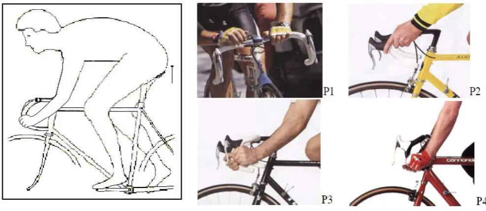
Figure 2 Riding posture (left) and four holding position (right)Cyclist has to use lower riding posture at position 3 and 4 for getting faster speed and reducing wind resistance. In order to disperse pressure happened on palm, the holding position area should as big as possible. Since the handlebar offered four different hold positions, cyclist can change the positions during riding for preventing one posture kept a long time and getting chance to take a rest. In recent years, the shape of handlebar has extremely changed from tube to more complex free form surface due to the application and development of manufacture processes and materials [2]. Therefore, this study aimed at exploring the reasonable contact area on each holding position and comfort of palm [3, 5].
3.2 Experimental samples and platform
In order to understand whether the comfort sensation will be affected by the shape of handlebar or not, three test samples are selected from market as shown in figure 2(a, b and c). The test sample, named S1, S2 and S3, have different shape and dimension. The width at position 1 is 4.6cm, 4.0cm and 3.2cm and position 2 is 3.7cm, 3.4cm and 3.2cm respectively. The angle of position 3 is 131 °, 105 ° and 90 ° and the length of position 4 is 7.5cm, 7.2cm and 6.6cm. The comfort sensation experiment is not dynamic test, so that three test samples have sequentially to ssemble on the test platform as shown in figure 2(d). All dimensions of test platform will be adjusted according to each tester’s characteristics such as tall, the length of arm, and the distance from hip to ground. This is a complicated experience and takes a lot of time[24].
Figure 3 Test Samples of handlebar 3.3 Experiment process
IJEDR1802044
International Journal of Engineering Development and Research (
www.ijedr.org
)
252
Figure 4 Experimental Process of comfort sensation of palm during riding3.4 Experimental analysis
In table 1, long dot line represents contact area and short dot line specifies pain area. According to design ruleand pressure analysis, the pain area on the palm should as small as possible that means a good handlebar can uniformly distribute pressure on the palm. The results showed in table 1 expose that the contact area of the test samples S1 and S2 are almost the same but both are larger than S3, and the contact area of S1 is as big as the palm. Sample S3, compared with S1 and S2, has the smallest contact area. For the pain area discussion, test sample handlebar S1 has bigger pain area at position 1 and the pain area of position 2 to position 3 is the part between the little finger and the wrist. The pain areas of test sample handlebar S2 concentrate on the part from center of palm to rim except position 3. The pain area of the test sample handlebar S3 is the largest in four test samples. Especially at the position 1, the pain area is almost the same with the contact area. Besides, the pain areas of position 2 to 4 have more than half of the contact area. To make a comprehensive survey about the pressure distribution to four test samples, the contact area is the region from the thumb and the index finger to the little finger[75]. The pain area concentrated on the regions of the thumb and the index finger, and between the little finger and wrist. Meanwhile, two nouns, the ratio of contact (RC) and the ratio of pain (RP), had been defined to explain the relationship with comfort sensation. The ratio of contact is defined as the contact area divided by the area of palm, and the ratio of pain is the pain area divided by the area of palm. And then analyze the correlation of RC, RP, the area of palm and comfort sensation by using statistical analysis. According to the analysis data, comfort sensation and contact area has positive correlation at position 1 and 2.
© IJEDR 2018 | Volume 6, Issue 2 | ISSN: 2321-9939
IJEDR1802044
International Journal of Engineering Development and Research (
www.ijedr.org
)
253
II.ERGONOMIC ASPECTS OF BICYCLE HANDLEWinston G et. al. describes handles for two commonly used hand tools, the chisel and the off-set pliers, are designed using ergonomic principles. These were sized for both males and females falling in the 5th percentile, 50th percentile and 95th percentile groupings[90,21]. The stresses developed in the ergonomically designed chisel handle while in use were analysed to verify the validity of the design. This chisel handle was then manufactured, and preliminary evaluation using electromyography was conducted. In these tests, the stresses exerted on the flexor and extensor muscles of the arm were measured and compared with those obtained during the use of a conventional handle[36]. Under similar working conditions, results clearly showed that the ergonomically designed handle allows higher working efficiency than existing handles.
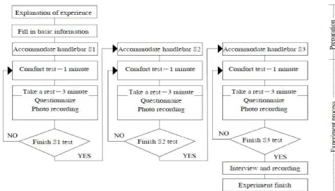
Figure 5 The three important areas to look at in bike ergonomics[17]
Figure shows the work of the shoulders is also the work of the upper body, up to the end of the breast-spine[77]. The lower back is working with the pelvis and helps to stabilize your body. Proper pedalling is not only the work of the legs, but of the whole body but the investigation is done on legs[61].
Sean P.et. al. investigated assembly of off-road bicycle handlebars with a stem that clamps the handlebar around its circumference would be expected to affect fatigue performance by introducing both assembly stresses and stress concentration[93]. Because the effect of clamping on fatigue performance is unknown and because of the need to insure structural reliability in the stem-handlebar assembly to prevent serious injury, the objectives of the work reported by the present article were fourfold [94]. One was to determine the stresses due to assembly and the stress concentration induced in a handlebar for two different clamp designs (i.e. 1-bolt and 2-bolt), a second was to determine experimentally the high cycle constant amplitude load fatigue lives of the two stem-handlebar assemblies, a third was to determine experimentally the variable amplitude load fatigue lives, and the fourth was to predict the variable amplitude load fatigue life with constant amplitude load fatigue test results. The handlebar was instrumented with strain gages and the assembly strains were measured when the stem clamps were tightened [97,98]. The handlebar was also loaded as a cantilever beam while the applied strains were measured for each assembly. Stresses were computed and the maximum stresses induced by clamping exceeded 200 MPa for both assemblies[50,53]. A method unique to this study was devised to determine the stress concentration at an arbitrary angular location around the circumference of the handlebar and for an arbitrary loading direction in the plane of the bicycle. For a load directed along an angle of 38° (clockwise rotation from horizontal viewed from the right), both stems created similar stress concentration; the location of maximum applied stress was shifted by 30° from the point that would be expected in the absence of assembly and the stress was increased by 40% at this location[30]. The measured fatigue lifetimes for constant amplitude loading were similar for the two stem designs but the variable amplitude load fatigue lifetime for the 1-bolt stem assembly was shorter than that for the 2-bolt stem assembly by 19%[33]. The fatigue lifetimes for variable amplitude loading based on constant amplitude load fatigue test results were predicted to within 3% and 33% for the 1-bolt and 2-bolt stems, respectively. Thus, constant amplitude load fatigue test results can be used to approximate the variable amplitude load fatigue life. However, the ranking of different assemblies may not be accurately indicated by constant amplitude load fatigue data[91].
IJEDR1802044
International Journal of Engineering Development and Research (
www.ijedr.org
)
254
They finds the proposed method allows manufacturing of the bent shape tubes with variable cross-section from fibre reinforced composites[43]. The original procedure by using an inner pressurized elastic mandrel is able to assure constant pressure upon the reinforcement material, the result being a compact composite, well pressed with an optimum reinforcement degree related the materials used[85]. Traditional methods that use a rigid mandrel manufacturing of bent tubes with variable cross-section as the presented handlebar could not be possible due to the fact that the mandrel cannot be released from the composite tube. The obtained handlebar has a significantly reduced weight (95 g) in comparison with aluminium alloy handlebar with the same dimensions (~250 g). Morphologic analyses revealed a good connection and compatibility between carbon and epoxy matrix. The procedure is relatively simple to put in practice and the costs are reduced[49,50]. The materials constants, experimentally obtained, an unsymmetrical orthotropic laminate, are in good agreement with the theoretical results based on the classical laminated plate theory that considered the composite material as a single-layer equivalent orthotropic model[65]. The FE results of the two important tests for the handlebar, requested by the safety requirements and test methods standard of mountain-bicycles, lateral bending test and torsional security test confirm that the carbon/ epoxy composite handlebar undergoes maximum principal stresses of 407.7 MPa in case of lateral bending and 220.6 MPa for the torsion test. Analysing the maximum principal stress values, its direction coinciding with the fibres direction of the second ply, the maximum value was under the ultimate stress experimentally measured[70]. Performing the lateral bending test on the manufactured handlebar test it could be noticed that the handlebar fulfil the safety requirements, being enough strength to undergo the total applied force of 2000 N. The maximum loading force obtained in the experimental analysis has validated the numerical simulation and, in the same time, the material proprieties were determined by both analytical and experimental way[39]. The safety coefficient is small, reason why, according to the designer options, the handlebar can be strengthened by additional plies inner placed in the maximum stressed area[58].III.CONCLUSION
This paper discusses the ergonomic aspects that can be incorporated in the design of a bicycle handle. The first step is to determine which factors contribute to comfort when riding a bicycle which results in human performance and fatigue. It has been found out by means of a survey with enthusiast cyclists that comfort is influenced by factors related to the cyclist (driver position, handle adjustments, body parts). This paper classified ergonomic aspects of bicycle handle, factors responsible for fatigue and analysis for the comfort positions. The most of the researchers presents there work in change seating position whereas this work focuses on the comfort position of bicycle handles. Hence there is a scoope to find out the fatigue develop during riding for a particular region
REFERENCES
[1] A. Palmgren, A., “Die Lebensdauer von Kugellagern,” Zeitschrift des Vereins Deutscher Ingenieure, Vol. 68, No. 14, pp. 339–34,1924
[2] Pippard, A.J.S., and Francis, W.E.,The stresses in a radially-spoked wire wheel under loads applied to the rim.‖ Philosophical Magazine, vol. 7 no. 1,pp. 233-285,1931
[3] Lea, F. C., “The Effect of Discontinuities and Surface Conditions on Failure Under Repeated Stress,” Engineering, Vol. 144, No. 2, , pp. 87–90, 140–144, 1937.
[4] Miner, M. A., “Cumulative Damage in Fatigue,” Journal of Applied Mechanics, Vol. 67, pp. 159. , 1945 [5] Sines, G. and Waisman, J. L., Metal Fatigue, McGraw-Hill, New York, NY, 1959.
[6] Almen, J. O. and Black, P. H., Residual Stress and Fatigue in Metals, McGraw-Hill, New York, NY, 1963. [7] Grover, H. J., Fatigue of Aircraft Structures, U.S. Government Printing Office, Washington, D.C., 1966. [8] Branton, P., Behavior, body mechanics and discomfort.Ergonomics 12, pp. 316–327,1969.
[9] Hertzberg, H.T.E., The human buttock in sitting: pressures, patterns, and palliatives.Am.Autom ob.Trans.72, pp.39–47,1972
[10] Drury, C.G. Handle for manual material handling. Applied Ergonomics, vol. 11, pp 35-42,1980.
[11] Richards, L.G., On the psychology of passenger comfort. In:Oborne, D.J., Levis, J.A. (Eds.), Human Factors in Transport Research, Vol.2.pp.15–23,1980.
[12] Tom Bendix, “Seated Trunk Posture at Various Seat Inclinations”, Human Factors, 26(6), pp. 695 – 703,1984. [13] Heuler, P. and Seeger, T., “A Criterion for Omission of Variable Amplitude Loading Histories,” International
Journal of Fatigue, Vol. 8, No. 4, pp. 225–230, 1986
[14] Metallic Materials and Elements for Aerospace Vehicle Structures (Mil-HDBK-5F), U.S. Department of Defense, MIL-HDBK-5 Coordination Activity, Wright-Patterson AFB, OH, 1990.
[15] Moore, A., Wells, R., Ranney, D.: Quantifying exposure in occupational manual tasks with cumulative trauma disorder potential. Ergonomics 34(12), pp. 1433–1453 ,1991
[16] Munehira Akita,Design of Ergonomics”, Ergonomics, Volume 34, No. : 6; pp 815 – 824,1991
[17] Fellows, G.L., Freivalds, A., Ergonomics evaluation of a foam rubber grip for tool handles.Appl. Ergon.22 (4), pp. 225–230.,1991
[18] W.M .Keyserling, M. Brouwer and B.A. Silverstein, “A checklist for evaluating ergonomic risk factors resulting from awkward postures of the legs, trunk and neck.” International Journal of Ergonomics, vol. 9 pp.283-301.,1992 [19] Jensen, C.V., Bendix, T.,Spontaneous movements with various seated-workplace adjustments.Clin.Biomech. 7,pp.
© IJEDR 2018 | Volume 6, Issue 2 | ISSN: 2321-9939
IJEDR1802044
International Journal of Engineering Development and Research (
www.ijedr.org
)
255
[20] Oh, S., Radwin, R.G.: Pistol grip power tool handle and trigger size effects on grip exertions and operatorpreference. Hum. Factors 35(3),pp. 551–569,1993.
[21] Winston G. Lewis & C. V. Narayan Design and sizing of ergonomic handles for hand tools. Applied Ergonomics, vol. 24, pp 351-356,1993
[22] Fransson-Hall, C., Kilbom, A.,. Sensitivity of the hand to surface pressure.Appl. Ergon.24 (3), pp.181–189,1993. [23] Mano, H., Oliver, R.L., Assessing the dimensionality and structure of the consumption experience: evaluation,
feeling, and satisfaction.J.Consum. Res.20, pp.451–466,1993.
[24] Kadefors, R., Areskoug Al Dahlman, S., Kilbom, A., Sperling, L., Wikstro.m, L., O. ster, J., An approach to ergonomic evaluation of hand tools.Appl. Ergon. 24 (3),pp. 203–211,1993
[25] Jianghong, Z., Long, T.,An evaluation of comfort of a bus seat.Appl.Ergon.25,pp. 386–392,1994
[26] Wilder, D., Magnusson, M.L., Pope, M, The effect of posture and seat suspension design on discomfort and back muscle fatigue during simulated truck driving.Appl.Ergon.25, pp.66–76, 1994
[27] Gurram, R., Rakheja, S., Gouw, G.J., A study of hand grip pressure distribution and EMG of finger flexor muscles under dynamic loads.Ergonomic s 38 (4), pp.684–699,1995
[28] Shütz, D. and Heuler, P., “The Significance of Variable Amplitude Fatigue Testing,” Automation in Fatigue and Fracture: Testing and Analysis, STP 1231, C. Amzallags, Ed., ASTM International, West Conshohocken, PA, pp. 201–220, 1994
[29] Specialized Announces Bike Brake, Handlebar Recall, U.S. Consumer Product Safety Commission, Office of Information and Public Affairs, pp. 95–155, 1995.
[30] Edwards, C., Marks, R.: Evaluation of biomechanical properties of human skin. Clin.Dermatol. 13(4),pp. 375– 380,1995.
[31] Gurram, R., Rakheja, S., Gouw, G.J.: A study of hand grip pressure distribution and EMG of finger flexor muscles under dynamic loads. Ergonomics 38(4), pp.684–699 ,1995
[32] Zhang, L., Helander, M.G., Drury, C.G,. Identifying factors of comfort and discomfort in sitting.Hum. Factors 38 (3), pp.377–389, 1996
[33] ISO-4210: Safety Requirements for Bicycles, International Organization for Standardization, Geneva, Switzerland, 1996.
[34] Petrone, N., Tessari, A., and Tovo, R., “Acquisition and Analysis of Service Load Histories in Mountain-Bikes,” Proceedings of the XXVth AIAS National Conference— International Conference on Material Engineering,Vol. II, Galatina, LE-Italy, pp. 851–858, 1996.
[35] Henri P. Gavin, ―Bicycle Wheel Spoke Patterns and Spoke Fatigue‖, ASCE Journal of Engineering Mechanics, vol 122, no. 8, (August 1996) pp. 736–742. August 1996.
[36] Anupam Pattanayal, Ashish Apoorva, Md. Shahabuddin, V.N.A. Naikan, “Ergonomic Design of Indian Cycle Rickshaw”, Industrial Engineering Journal, Vol.32 No. 2, 1997.
[37] Habes, D.J., Grant, K.A., An electromyographic study of maximum torques and upper extremity muscle activity in simulated screwdriving tasks.Int.J.Ind.Ergon.20, pp.339–346,1997
[38] Helander, M.G., Zhang, L., Field studies of comfort and discomfort in sitting.Ergonomic s 40 (9), 895–915,1997 [39] Dowling, N. E., Mechanical Behavior of Materials, 2nd Edition, Prentice-Hall, Upper Saddle River, New Jersey,
1998.
[40] Mestdagh, K. Personal perspective: in search of an optimum cycling posture. Applied Ergonomics,vol. 29, no. 5, pp 325-334,1998.
[41] De Lorenzo, D. S. and Hull, M. L., “Quantification of Structural Loading During Off-Road Cycling,” Journal of Biomechanical Engineering, Vol. 121, No. 4, pp. 399–404, 1999.
[42] Nicol, Scot, Metallurgy for cyclists I: The basics‖, http://www.63xc.com/scotn/metal.htm, March 1999. [43] D. Arola, P.G. Reinhall, M.G. Jenkins , S.C. Iverson, An Experimental Analysis Of A Hybrid Bicycle Frame‖,
Journal of Experimental Techniques. May/ June 1999.
[44] Karl H. E. Kroemar,, Assessment of human muscle strength for engineering purposes” Ergonomics, vol. 42, no.1, pp. 74 -93 Jan 1999
[45] Berguer, R., Gerber, S., Kilpatrick, G., A comparison of forearm and thumb muscle electromyographic responses to the use of laparoscopic instruments with either a finger grasp or a palm grasp.Ergonomics 42 (12),pp.1634– 1645,1999.
[46] Johansson, L., Kjellberg, A., Kilbom, A., Hagg, G., Perception of surface pressure applied to the hand.Ergonomic s 42 (10),pp.1274–1282,1999
[47] Lowe, B.D., Freivalds, A., Effect of carpal tunnel syndrome on grip force coordination on hand tools.Ergonomics 42 (1), pp. 550–564,1999.
[48] Chang, S.R., Park, S., Freivalds, A.,Ergonomic evaluation of the effects of handle types on garden tools.Int.J.Ind.Ergon.24, pp. 99–105,1999.
[49] Kumar, S., Narayan, Y., Bjornsdottir, S.,Comparison of the sensitivity of three psychophysical techniques to three materials handling task variables.Ergonomics 42 (1),pp. 61–73,1999.
IJEDR1802044
International Journal of Engineering Development and Research (
www.ijedr.org
)
256
[51] Chang, H.H., Wang, M.J.J., Evaluating factors that influence hand-arm stress while operation an electricscrewdriver.Appl.Ergon.31, pp.283–289,2000
[52] Chao, A., Kumar, A.J., Emery, C.T.N.D., Nagarajarao, K., You, H.,2000. An ergonomic evaluation of clecopliers. Proceedings of the IEA 2000/HFES 2000 Congress, pp.4-441–4-442,2000.
[53] Kim, C.H., Kim, T.K., Maximum torque exertion capabilities of Korean at varying body postures with common hand tools. Proceedings of the IEA Congress,2000.
[54] Niemel.a, T., Lepp.anen, M., P.aivinen, M., Mattila, M., Evaluation of an experimental testing system for non-powered hand tools.In: Proceedings of the IEA 2000/HFES 2000 Congress ,2000.
[55] Slater, K.,. In: Thomas, C.G. (Ed.), Human Comfort. Charles C. Thomas, Springfield, IL. Smith, C.A., Mirka, G.A., Myers, K.A., 2000. Ergonomic hand tool interventions for the furniture manufacturing industry.Proceedings of the IEA/HFES 2000 Congress, pp.99–104, 2000
[56] Liao, M.H., Drury, C.G., Posture discomfort and performance in a VDT task.Ergono mics 43 (3), pp. 345– 359,2000
[57] Trek Bicycle Corp. Announces Recall of Road Bikes and Handlebar Stems,U.S. Consumer Product Safety Commission, Office of Information and Public Affairs, pp. 192, 2000.
[58] Freund, F., Takala, E.P., Toivonen, R., Effects of two ergonomic aids on the usability of an in-line screwdriver.Appl. Ergon.31, pp. 371–376, 2000.
[59] Vergara, M., Page, A., System to measure the use of the back rest in sitting-posture office tasks.Appl.Ergon.31, 247–254, 2000.
[60] Wakula, J., Landau, K., Ergonomic analysis of grapevine pruning and wine harvesting to define work and hand tools design requirements.Proceedin gs of the IEA/HFES 2000 Congress, pp.635–637, 2000
[61] Wakula, J., Beckmann, T., Hett, M., Stress-strain analysis of grapevine pruning with powered and non-powered hand tools. Proceedings of the IEA/HFES 2000 Congress, pp.639–641. 2000
[62] Rose, L., Ericson, M., Ortengren, R., Endurance time, pain and resumption in passive loading of the elbow joint.Ergonomics 43 (3), 405–420,2000
[63] Lin, J.H., Radwin, R.G., Richard, T.G.,Dynamic biomechanical model of the hand and arm in pistol grip power hand tool usage.Ergono mics 44 (3), pp. 295–312,2001
[64] Matern, U.,. Principles of ergonomic instrument handles. Minimally Invasive Ther.Appl.Technol.10 (3), pp.169– 173,2001
[65] McGorry, R.W., A system for the measurement of grip forces and applied moments during hand tool use.Appl. Ergon. 32,pp. 271–279,2001.
[66] Spielholz, P., Boa, S., Howard, N. A practical method for ergonomic and usability evaluation of hand tools: a comparison of three random orbital sander configurations.Applied Occup. Environ.Hyg. 16 (11),pp. 1043–1048, 2001.
[67] Ciriello, V.M., Snook, S.H.,Webster, B.S.,Psychophysical study of six hand movements.Ergono mics 44 (10), pp. 922–936.,2001
[68] Eikhout, S.M., Bronkhorst, R.D., van der Grinten, M.P.,. Evaluation of a new scraper.In: Proceedings of the 45th HFES Congress 2000, Minneapolis.2001
[69] de Looze, M.P., de Kuijt-Evers, L.F.M., van Die.en, J., Sitting comfort and discomfort and the relationships with objective measures.Ergonomic s 46 (10),pp. 985–997,2003.
[70] Hal W. Hendrick, „Determining the cost–benefits of ergonomics projects and factors that lead to their success’. Applied Ergonomics 34,pp.419–427, 2003
[71] Kuijt-Evers, L.F.M., Groenesteijn, L., de Looze, M.P. , & Vink, P. Identifying factors of comfort in using hand tools. Applied Ergonomics, vol. 35, pp 453-458,2004.
[72] ASTM Standard F2868-10, "Standard Specification for Condition 2 Bicycle Frames," ASTM International, West Conshohocken, PA, www.astm.org.Wilson, D.G. Bicycling Science. MIT Press.2004
[73] Kong, Y., Lowe, B.: Optimal cylindrical handle diameter for grip force tasks. Int. J. Ind. Ergon. 35(6), 495– 507,2005
[74] Aldien, Y., Welcome, D., Rakheja, S., Dong, R., Boileau, P.E.: Contact pressure distribution at hand–handle interface: role of hand forces and handle size. Int. J. Ind. Ergonom. 35(3),pp.267–286,2005
[75] Aldien, Y., Welcome, D. S., Rakheja, R. D. & Boileau, P. E. Contact pressure distribution at hand–handle interface: role of hand forces and handle size. International Journal of Industrial Ergonomics, vol. 35, pp 267-286, 2005.
[76] Silberman, M.R., Webner, D., Collina, S. Shiple, B.J., Road Bicycle fit, Clinical Journal of Sport Medicine, 15(4), pp. 271 -276, 2005.
[77] David E.H. Jones, The Stability of the bicycle‖, Feature Article. From the Archives, September 2006.
[78] Wu, J.Z., Cutlip, R.G., Andrew, M.E., Dong, R.G.: Simultaneous determination of the nonlinear-elastic properties of skin and subcutaneous tissue in unconfined compression tests.Skin Res. Technol. 13(1), pp.34–42,2007.
© IJEDR 2018 | Volume 6, Issue 2 | ISSN: 2321-9939
IJEDR1802044
International Journal of Engineering Development and Research (
www.ijedr.org
)
257
[80] Garcia-Lopez, J., Rodriguez-Marroyo, J.A., Juneau, C.-E., Peleteiro, J., Martinez, A.C. and Villa, J.G., Referencevalues and improvements of aerodynamic drag in professional cyclists‖, J. Sports Sci., 26(3), pp. 277-286,2008 [81] Seo, N.J., Armstrong, T.J.: Investigation of grip force, normal force, contact area, hand size,and handle size for
cylindrical handles. Hum. Factors 50(5), pp.734–744,2008
[82] David Stevens, ―The Stability and Handling Characteristics of Bicycles‖, The University of New South Wales, School of Mechanical and Manufacturing Engineering, June 2009.
[83] Godo, M.N, Corson, D. and Legensky, S.M., An Aerodynamic Study of Bicycle Wheel Performance using CFD‖, 47th AIAA Aerospace Sciences Annual Meeting, Orlando, FL, USA, 5-8 January, AIAA Paper No. 2009-0322,2009
[84] M. Enzweiler and D. Gavrila. Monocular pedestrian detection: Survey and experiments. 31(12),pp.2179-2195, December 2009.
[85] Bressel, E., Bliss, S., Cronin, J., A field-based approach for examining bicycle seat design effects on seat pressure and perceived stability. Appl. Ergon. 40, pp.472-476,2009
[86] Lambros Laios, John Giannatsis, “Ergonomic Evaluation and redesign of children bicycle based on anthropometric data”, Applied Ergonomics pp.1-8,2009
[87] Stephen Smaldone, Chetan Tonde, Vancheswaran K. Ananthanarayanan, Ahmed Elgammal, and Liviu Iftode, Improving Bicycle Safety through Automated Real-Time Vehicle Detection‖ Department of Computer Science Rutgers University 110 Frelinghuysen Rd, Piscataway, NJ 08854, August 2010.
[88] Lambros Laios, John Giannatsis, „Ergonomic evaluation and redesign of children bicycles based on anthropometric data’. Applied Ergonomics 41,pp. 428–435,2010
[89] Garneau, C.J., Parkinson, M.B.: Optimization of product dimensions for discrete sizing applied to a tool handle. Int. J. Ind. Ergonom. 42(1), pp.1–9 ,2011.
[90] Matt Wilkinson, The Winston Churchill Memorial Trust Travelling Fellowship 2011‖, Bicycle Frame Building in the USA. May 2011.
[91] Forrest Dwyer, Adrian Shaw, Richard Tombarelli, ― Material and Design Optimization for an Aluminum Bike Frame‖, Worcester Polytechnic Institute. April 2012.
[92] H. K. Epema, S. van den Brand, Wouter Gregoor, J. D. G. Kooijman, H. P. Pereboom, D. C. Wielemaker, C. J. van der Zweep. 9th Conference of the International Sports Engineering Association (ISEA),Bicycle Design: A different approach to improving on the world human powered speed records’.2012
[93] Joachim Vanwalleghem, Frederik Mortier, Ives De Baere, Mia Loccufier, Wim Van Paepegem. 9th Conference of the International Sports Engineering Association (ISEA)„Design of an instrumented bicycle for the evaluation of bicycle dynamics and its relation with the cyclist’s comfort,2012
[94] Derek Covilla, Steven Begga, Eddy Eltona, Mark Milnea, Richard Morrisa, Tim Katza, Parametric finite element analysis of bicycle frame geometries‖, School of Computing, Engineering and Mathematics, University of Brighton, Lewes Rd, Brighton, BN2 4GJ, UK, April 2014.
[95] Sagar Pardeshi, Pankaj Desle ―Design and Development of Effective Low Weight Racing Bicycle Frame‖, International Journal of Innovative Research in Science, Engineering and Technology (IJIRSET). December 2014. [96] Derek Covill, Steven Begg, Eddy Elton, Mark Milne, Richard Morris, Tim Katz. School of Computing,
Engineering and Mathematics, University of Brighton, ‘Parametric finite element analysis of bicycle frame geometries,2014
[97] Balasubramanian , M. Jagannath, K. Adalarasu, Rehabilitation Bioengineering Group, Department of Engineering Design, IIT Madras,Muscle fatigue based evaluation of bicycle design’.2014
[98] Yi-Lang Chen , Yi-Nan Liu „Optimal protruding node length of bicycle seats determined using cycling postures and subjective ratings’. Department of Industrial Engineering and Management, Ming Chi University of Technology, pp. 222-228,2014
[99] Paolo Baldissera , Cristiana Delprete „Structural design of a composite bicycle fork’. Materials and Design, pp. 60,2014.
[100] J. Szecsia, A. Straubea, C. FornusekbaCenter „Leg general muscle moment and power patterns in able-bodied subjects during recumbent cycle ergometry with ankle immobilization’. Exercise, Health and Performance Faculty Research Group, Faculty of Health Sciences, University of Sydney , Medical Engineering & Physics, pp. 36,2014. [101] Paul B.,Mircea C. Nicolae B. Petru B,Design and Analysis of Carbon/epoxy Composite Bicycle
Handlebar,pp.145-149,2014
![Figure 1 Comfort element for short and long range bike ride [17]](https://thumb-us.123doks.com/thumbv2/123dok_us/8197907.1369306/3.595.139.459.53.278/figure-comfort-element-short-long-range-bike-ride.webp)
![Figure shows the work of the shoulders is also the work of the upper body, up to the end of the breast-spine[77]](https://thumb-us.123doks.com/thumbv2/123dok_us/8197907.1369306/6.595.113.499.166.359/figure-shows-work-shoulders-work-upper-breast-spine.webp)
