e-ISSN: 2278-067X, p-ISSN: 2278-800X, www.ijerd.com
Volume 7, Issue 1 (May 2013), PP. 14-24
Dynamic Voltage Restorer for Distribution System
S.Saravanan
1, M.Solaimanigandan
2, T.Tharaneetharan
3, V.Varunraj
4,
S.Parthasarathy
5Department of Electrical and Electronics Engineering, Valliammai Engineering College, Kanchipuram, India.
Abstract:- Power quality is one of the major concerns in the present era. Out of various power quality
issues, voltage sag is considered to be a frequently occurring phenomena that can be rectified by the use of custom power devices like Dynamic Voltage Restorer (DVR), which is the most efficient and effective modern custom power device used in power distribution networks. Its appeal includes lower cost, smaller size, and its fast dynamic response to the disturbance. In this paper, modelling, analysis and simulation of a high efficient Dynamic Voltage Restorer (DVR) was done in MATLAB. The efficiency of the DVR depends on the performance of the control technique involved in switching of the inverters. Hence different control technique like discrete PWM scheme using PI controller hysteresis current controller and hysteresis voltage controller were used. Based on the comparison between the performance of PI controller, hysteresis current controller and hysteresis voltage controller, in controlling the switching of PWM inverter switches, the optimum controller that improves the performance of Dynamic Voltage Restorer (DVR) is suggested.
Keywords:- Dynamic Voltage Restorer (DVR), Voltage sag, Hysteresis voltage control, Hysteresis
current control, PI controller.
I.
INTRODUCTION
Power distribution systems, ideally, should provide their customers with an uninterrupted flow of energy at smooth sinusoidal voltage at the contracted magnitude level and frequency. However, in practice, power systems, especially with distribution systems, have numerous nonlinear loads, which significantly affect the quality of power supplies. As a result of the nonlinear loads, the purity of the waveform supplies is lost .This ends up producing many power quality problems. Apart from nonlinear loads, some system events, both usual (e.g. capacitor switching, motor starting) and unusual (e.g. faults) could also inflict power quality problems. Power quality is an issue that is become increasingly important to electricity consumers at all levels of usage. Sensitive equipment and non-linear loads are now more common place in both industrial sectors and domestic environment [1].Power quality problems encompass a wide range of disturbances such as voltage sag, voltage swell, flickers, harmonic distortions, impulse transients Land interruptions. Faults at either the transmission or distribution level may cause transient voltage sag or swell in the entire system or swell in the entire system or large part of it. Voltage drop will also occur in the heavy load conditions. Short circuits, starting large motors, sudden changes of load, and energization of transformers are the main causes of voltage sags. Voltage sag is the decrease of 0.1 to 0.9 pu in the rms voltage level at system frequency and with the duration of half a cycle to one minute. Further, they could be either balanced or unbalanced depending on factors such as distance from the fault and the transformer connections. Voltage swell, on the other hand, is defined as an event in which the RMS voltage increases between 1.1 and 1.8 pu at the power frequency .It lasts for durations of 0.5 to 1 minute. Voltage swells are not as important as voltage sags because they are less common in distribution systems. Voltage sag and swell can cause sensitive equipments (such as found in semiconductor chemical plants) to fail, or shutdown, as well as create a large current unbalance that could blow fuses or trip breakers. These effects can be very expensive for the customer, ranging from minor quality variations to production downtime and equipment damage [1].
undervoltages within specified limits, acceptance of fluctuations, and poor factor load without significant effect on the terminal voltage [1].
The custom devices which are used for voltage sag mitigation are Dynamic Voltage Restorer(DVR), Active Series Compensators, Distribution Static Synchronous Compensators(DSTATCOM) , Solid State(static) Transfer Switch(SSTS), Static UPS with Minimal Energy Storage, Backup Storage Energy Supply(BSES), Flywheel with UPS System, Battery Energy Storage Systems (BESS), Distribution Series Capac Magnetic Energy Systems(SMES) , Static Electronic Tap Changers(SETC), Solid-State Fault Current Limiter(SSFCL), Static Var Compensator(SVC), Thyristor Switched Capacitor(TSC), and Uninterruptible Power Supplies(UPS) [2].
Each of the custom devices has its own benefits and limitations .The most effective type of these devices is considered to be the Dynamic Voltage Restorer(DVR).The SVC pre-dates the DVR , but the DVR is still preferred because the SVC has no ability to control active power flow. DVR is less cost while compared to UPS. Rather than high cost UPS also needed high level of maintenance because batteries leak and have to be replaced often as every five years. Also DVR has a higher energy capacity and lower costs compared to the SMES device. Furthermore, the DVR is smaller in size and costs less compared to DSTATCOM. In addition to voltage sags and swells compensation, DVR can also added other features such as harmonics and power factor correction. Compared to other devices DVR is provides the best economic solutions for its size and capabilities. This power electronic converter-based compensator is connected in series with the distribution feeder between the supply and the loads. Its main function is to mitigate any supply voltage disturbance, especially voltage sag, by inserting a voltage with the required magnitude and phase shift in order to restore the load voltage to its rated value [1].
II.
DYNAMIC
VOLTAGE
RESTORER
(DVR)
COMPONENTS
The power circuit of DVR consists of following main five components: Voltage source inverter (VSI), Voltage injection transformer, DC energy storage device, low pass filter and a control method as shown in Fig.1.
A. Injection/Booster Transformer
Its basic function is to step up the ac low voltage supplied by the VSI to the required voltage. It is a specially designed transformer that attempts to limit the coupling of noise and transient energy from the primary side to secondary. It connects the DVR to the distribution network through the HV windings. In addition it also performs the isolation of the load from the system. In case of three phase DVR, three single phase injection transformers are used [2, 4].
B. Passive Filter
A passive low pass filter consists of an inductor and capacitor. It can be placed either at high voltage side or the inverter side of the injection transformer. It is used to filter out the switching harmonic components from the injected voltage . By placing the filter at the inverter side , the higher order harmonics are prevented from penetrating into the transformer. When the filter is placed on the high voltage side , the harmonics can penetrate into the high voltage side of the transformer , a higher rating is required. Filter has a small rating approximately 2% of the load MVA connected to delta-connected tertiary winding of the injection transformer [1].
C. Voltage Source Inverter
The Voltage Source Inverter (VSI) or simply the inverter , which converts the dc voltage from the energy storage unit(or the dc link) to a controllable three phase ac voltage. This voltage is boosted through the injection transformer to the main system. The inverter switches are normally fired using a sinusoidal Pulse Width Modulation (PWM) scheme. The PWM generates sinusoidal signals by comparing a sinusoidal wave with a sawtooth wave and sending appropriate signals to the inverter switches. Usually the rating of VSI is low voltage and high current due to the use of step up injection transformers [1,4].
`
D. DC Energy Storage Device
The purpose is to supply the necessary energy to the VSI via a dc link for the generation of injected voltages. The different kinds of energy storage devices are superconductive magnetic energy storage (SMES), batteries, fly wheels, super capacitors and capacitors. The capacity of the stored energy directly determines the duration of the sag which can be mitigating by the DVR. Batteries are the common choice and can be highly effective if a high voltage configuration is used. This high voltage string of batteries can be placed across the regulated dc bus with little or no additional circuitry. For Batteries and SMES, DC to AC conversion(inverters) is necessary, while for flywheels AC to AC conversion required [1,4].
E. Hysteresis Voltage Controller
Here we are using a conventional hysteresis voltage control technique which is one type of nonlinear voltage control based on voltage error. Fig.2 shows the principles of hysteresis voltage control. It consists of a comparison between the output voltage Vo and the tolerance limits (VH, VL) around the reference voltage
Vref.While the output voltage Vo is between upper limit VH and lower limit VL, no switching occurs and when
the output voltage crosses to pass the upper limit (lower band) the output voltage is decreased (increased) [10,11].
F. Hysteresis Current Controller
In a hysteresis controller, the hysteresis comparators are used to impose hysteresis around the reference current. Among all current control techniques, the hysteresis controller is widely used because of its simplicity of implementation and fast response current loop. This method does not need any knowledge of load parameters and it also has maximum current limits.
Fig .2: Principle of operation of hysteresis voltage controller
However, the main disadvantage is the variation of switching frequency during load parameter variation of fundamental period [5, 7, 8].
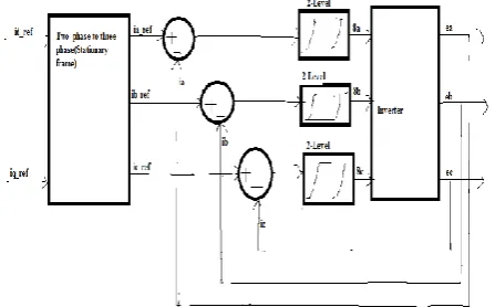
As shown in the fig.3 the reference current values will be converted from two phase to three phase variables by the use two phase to three phase transformation method. Then three phase reference current values will be compared with actual current and error value will be produced. Based on the error value the two level hysteresis controller will give the gate signals for the semiconductor switches of voltage source inverter and the current value will be maintained constant.
Fig.3: Block diagram of conventional hysteresis current controller
III.
OPERATING
PRINCIPLE
of DVR
The single phase DVR is employed for low power loads while three phase DVR is employed for all practical high power applications as in industrial loads and domestic loads. The basic function of the DVR is to inject a dynamically controlled voltage VDVR generated by a force commutated converter in series
means that any differential voltages caused by transient disturbances in the ac feeder will be compensated by an equivalent voltage generated by the converter and injected on the medium voltage level through the boost transformer.
The DVR works independently of the type of fault or any event that happens in the system, provided that the whole system remains connected to the supply grid, i.e. the line breaker does not trip. For most practical cases, a more economical design can be achieved by only compensating the positive and negative sequence components of the voltage disturbance seen at the input of the DVR. This option is reasonable because for a typical distribution bus configuration, the zero sequence part of a disturbance will not pass through the step step down transformer because of infinite impedance for this component [1].
The DVR has two modes of operation which are: standby mode and boost mode. In standby mode(VDVR=0), the boost transformer’s low voltage winding is shorted through the converter. No
switching of semiconductors occurs in this mode of operation, because the individual converter legs are triggered such as to establish a short-circuit path for the transformer connection. Therefore, only the comparatively low conduction losses of the semiconductors in this current loop contribute to the losses. The DVR will be most of the time in this mode. In boost mode(VDVR>0), the DVR is injecting a compensation
voltage through the booster transformer due to a detection of supply voltage disturbance [2].
IV. SIMULATION AND RESULTS
A. Test System
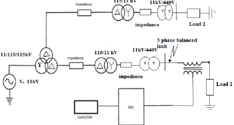
The single line diagram of test system of DVR is shown in fig. 4 .It is composed by a 11kV, 50Hz, generating system feeding two transmission lines through a three winding transformer connected in Y/Δ/Δ, 13/115/115kV. Such transmission lines feed two secondary transmission lines through the transformers connected in Δ/Y, 115/11kV.These two secondary transmission systems feed the two distribution networks through the transformers connected in Y/Y, 11kV/440V. To verify the working of DVR for voltage compensation three phase balanced fault is applied at point x at resistance 0.01 for time duration of 0.1s. The DVR is simulated to be in operation only for the duration of fault.
Fig.4: Block diagram of the test system
B. Case 1: Source and Load Without Fault
Here a normal power system is considered and there is no fault condition is applied to the system. So the output voltage waveform obtained is sinusoidal in nature as shown in Fig.6.
Table I: SYSTEM PARAMETERS USED IN SIMULATION
Sr.No System Quantities Standards 1. Three phase source 11kV, 50Hz
2. Step up transformer Y/Δ/Δ, 11/115/115kV 3. Transmission line parameters R=0.001Ω, L=1.33𝜇𝐻
5. Distribution load parameters R=14Ω, L=1mH
6. Inverter IGBT based, 3 arms, 6 pulse, Carrier frequency=1080Hz,
Sample time=5𝜇s
7. PI controller KP=0.5,Ki=50,Sample time=50𝜇s
8. DC Voltage source 250V
9. Injection/Linear/Isolation transformer 1:1 turns ratio, 440/440V
Fig.5: Simulink diagram of source and load without fault
Fig.6: Output voltage waveform of source and load without fault.
C. Case 2: Source and Load with Three Phase Balanced Fault
Here three phase balanced fault is applied to the test system with a fault resistance value of 0.01𝛀 and sag interval of 0.1s. Here the three phase balance fault is applied between the time period of 0.1 to 0.2s and the voltage sag condition is created. Here the voltage sag value is 17 percentage of output voltage.
Fig.8: Output voltage waveform of source and load with three phase balanced fault
D. Case 3: Voltage Sag Compensation by DVR with Discrete PWM Scheme Using PI Controller
Here for the test with DVR which is controlled by discrete PWM scheme using PI controller the three phase balanced fault is applied with a fault resistance of 0.01𝛀 for a sag time of 0.1s. Here the fault condition is applied between the time period of 0.1 to 0.2s and voltage sag condition is created in the system. This control scheme based on PI controller is able to compensate percentage of voltage sag value.
Fig.9: Simulink diagram of DVR with Discrete PWM scheme using PI Controller
Fig.11: Discrete PI controller
Fig.12: Output voltage waveform of DVR with discrete PWM scheme using PI controller
E. Case 4: Voltage Sag Compensation by DVR with Hysteresis Voltage Control Method
Now the test system with DVR which is controlled by hysteresis voltage control method undergone voltage sag condition created by the three phase balanced fault. Hare the fault resistance is 0.01𝛀 and sag time is 0.1s. The fault condition is applied between the time period of 0.1 to 0.2s. This DVR based on hysteresis voltage controller compensated 100 percentage of voltage sag condition.
Fig.14: Simulink model of voltage sag detection of hysteresis voltage control method
Fig.15: Simulink model of hysteresis voltage controller
Fig.16: Output voltage waveform of DVR with hysteresis voltage control method
F. CASE 5: Voltage Sag Compensation by DVR with Hysteresis Current Control Method
Three phase balanced fault is applied to the same system with DVR which is controlled by hysteresis current control method with a fault resistance of 0.01𝛀 and sag time of 0.1 sec. The fault condition applied between the time period of 0.1 to 0.2s and voltage sag condition is created in the system. This DVR based on hysteresis current controller compensated 98 percentage of voltage sag.
Fig.18: Voltage sag detection scheme of hysteresis current control method
Fig.19: Simulink model of hysteresis current controller
Fig.20: Output voltage waveform of DVR with hysteresis current control method
G. Comparison of Discrete PWM Scheme using PI Controller, Hysteresis Voltage Control Method and Hysteresis Current Control Method
Calculation:
1) Case 1: Source and Load Without Fault
Actual output voltage of the system= 425V. Voltage sag produced= 0V.
2) Case 2: Source and Load with Three Phase Balanced Fault
Actual output voltage of the system= 425V.
Output voltage of the system during voltage sag condition= 354V. Voltage sag produced= 425-354=71V.
Voltage sag value as the percentage of actual output voltage= 354/425*100 = 17 %.
3) Case 3: Voltage Sag Compensation by DVR with Discrete PWM Scheme Using PI Controller
Actual output voltage of the system= 425V.
Voltage sag produced= 425-354 = 71V.
Output voltage with PI controller= 400V. Injected voltage by the DVR= 400-354 = 46V.
Voltage improved in sag condition by the DVR with discrete PWM scheme using PI controller as the percentage of voltage sag=46/71
=65%.
4) Case 4: Voltage Sag Compensation by DVR with Hysteresis Voltage Control Method
Actual output voltage of the system= 425V.
Output voltage of the system during voltage sag condition= 354V. Voltage sag produced= 425-354
= 71V.
Output voltage with hysteresis voltage control method= 425V. Injected voltage by the DVR= 425-354
= 71V.
Voltage improved in sag condition by the DVR with hysteresis voltage control method as the percentage of voltage sag= 71/71*100
=100%.
5) Case 5: Voltage Sag Compensation by DVR with Hysteresis Current Control Method
Actual output voltage of the system= 425V.
Output voltage of the system during voltage sag condition= 354V. Voltage sag produced= 425-354
= 71V.
Output voltage with hysteresis current control method= 424V. Injected voltage by the DVR= 424-354
= 70V.
Voltage improved in sag condition by the DVR with hysteresis current control method as the percentage of voltage sag= 70/71*100
=98%.
V. CONCLUSION
In this project we have analysed the control of DVR based on discrete PWM technique using PI controller, hysteresis voltage control method and hysteresis current control method. The simulation results shows that hysteresis voltage control method works efficient while compared to the discrete PWM technique using PI controller and hysteresis current control method. The discrete PWM scheme using PI controller compensated 65% of the voltage sag condition and hysteresis current control method compensated about 98% of the voltage sag condition. But, the hysteresis voltage control technique compensated 100 % of the voltage sag condition.
ACKNOWLEDGEMENT
The authors wish to thank the authorities of Valliammai Engineering College, Kanchipuram, India for the facilities provided to prepare this paper.
REFERENCES
[1]. Chellai Benachaiba and Brahim Fedri, “Voltage Quality Improvement Using DVR”, Electrical Power Quality and Utilisation, Journal Vol.XIV, No.1, pp.39-45, 2008.
[2]. Chris Fitzer, Mike Barnes, and Peter Green, “Voltage Sag Detection Technique for a Dynamic Voltage Restorer”, IEEE Transactions on Industry Applications, Vol.40, No.1, pp.203-212, January/February 2004.
[3]. Roger C.Dugan, Mark F.McGranaghan, Surya Santoso, and H.Wayne Beaty, Electrical Power Systems Quality, Second Edition, Tata McGraw Hill Education Private Limited, New Delhi, 2008.
[4]. Mahmoud A.El-Gammal, Amr.Y.Abou-Ghazala, and Tarek.I. El-Shennawy, “DynamicVoltage Restorer (DVR) for Voltage Sag Mitigation”, International Journal on Electrical Engineering and Informatics-Vol.3, N0.1, pp.1-11, 2001.
[6]. B.Ferdi, C.Benachaiba, S.Dib, and R.Dehini, “Adaptive PI control of Dynamic Voltage Restorer Using Fuzzy Logic”, Journal of Electrical Engineering: Theory and Application Vol.1,Iss.3, pp.165-173, 2010.
[7]. Huifeng Mao, Xu Yang,, Zenglu Chen, and Zhaoan Wang, “A Hysteresis Current Controller for Single-Phase Three-Level Voltage Source Inverters”, IEEE Transactions on Power Electronics, Vol.27,N0.7, pp.3330-3339, July 2012.
[8]. P.Jeyaprakash, Bhim Singh, Senior , and D.P.Kothari, “Current Mode Control of Dynamic Voltage Restorer for Power Quality improvement in Distribution System”, 2nd IEEE International Conference on Power and Energy (PECon 08), Johor Baharu, Malaysia, pp.301-306, December 1-3, 2008. [9]. Jhon Godsk Nielsen, Michael Newman, Hans Nielsen, and Frede Blaabjerg, “Control and Testing
of a Dynamic Voltage Restorer at Medium Voltage Level”, IEEE Transactions on Power Electronics, Vol.19, No.3, pp.806-813, May 2004.
[10]. F.A.L.Jowder, “Design and analysis of dynamic voltage restorer for deep voltage sag and harmonic compensation”, IET Generation, Transmission & Distribution,vol.3, Iss.6, pp.547-560, pp.547-560, 2009.
[11]. Fawzi A.L.Jowder, “Modeling and Simulation of Dynamic Voltage Restorer(DVR) Based on Hysteresis Voltage Control, The 33rd Annual Conference of the IEEE Industrial Electronics Society (IECON), Taipei, Taiwan, pp.1726-1731, Nov.5-8, 2007.
[12]. K.R.Padiyar, Facts Controllers in Power Transmission and Distribution, First Edition, New Age International (P) Limited, Publishers, 2007.
[13]. Pirjo Heine, and Matti Lehtonen, “Voltage Sag Distributions Causedby Power System Faults, IEEE Transactions on Power Systems, Vol.18, No.4, pp.1367-1373, November 2003.
[14]. Muhammad H.Rashid, Power Electronics Circuits, Devices and Applications , Third Edition , Pearson Education, Inc, 2004.
[15]. S.V.Ravi Kumar and Siva Nagaraju “Simulation of D-STATCOM and DVR in Power Systems”,APRN Journal of Engineering and Applied Sciences, Vol.2, No.3, pp.7-13, June 2007. [16]. J.Ravindranadh, Y.Naveen Kumar, K.Durga Syam Prasad, and CH. Sai Babu, “Power Quality
Improvement by Unified Power Quality Conditioner using PI & ANN Controller for DC Link Current/ Voltage with Hysteresis Control, International Journal of Engineering Science & Advanced Technology (IJESAT) ,Vol.3, Iss.1, pp.44-52, Jan-Feb 2013.
[17]. R.H.Salimin and M.S.A.Rahim, “Simulation of DVR Performance for Voltage Sag Mitigation,The 5th International Power Engineering and Optimization Conference (PEOCO 2011), Shah Alam, Selangor, Malaysia, pp.261-266, June 6-7, 2011.
[18]. H.P.Tiwari and Sunil Kumar Gupta, “Dynamic Voltage Restorer Based on Load Condition”, International Journal of Innovation, Management and Technology, Vol.1, N0.1, pp.75-81, April 2010. [19]. Yun Wei Li, D.Mahinda Vilathagamuwa, Poh Chiang Loh, , and Frede Blaabjerg, “A