Citation: Aalimahmoodi, Khadijeh, Gholami, Asghar and Ghassemlooy, Fary (2019) Impact of
Camera Parameters on the OCC based Indoor Positioning System. In: The 2nd West Asian
Colloquium on Optical Wireless Communications (WACOWC2019): 27-28 April, Shahid
Beheshti University, Tehran, Iran. IEEE, Piscataway, NJ, pp. 96-99. ISBN 9781728137681,
9781728137674
Published by: IEEE
URL:
https://doi.org/10.1109/wacowc.2019.8770205
<https://doi.org/10.1109/wacowc.2019.8770205>
This version was downloaded from Northumbria Research Link:
http://nrl.northumbria.ac.uk/40177/
Northumbria University has developed Northumbria Research Link (NRL) to enable users to
access the University’s research output. Copyright
©and moral rights for items on NRL are
retained by the individual author(s) and/or other copyright owners. Single copies of full items
can be reproduced, displayed or performed, and given to third parties in any format or
medium for personal research or study, educational, or not-for-profit purposes without prior
permission or charge, provided the authors, title and full bibliographic details are given, as
well as a hyperlink and/or URL to the original metadata page. The content must not be
changed in any way. Full items must not be sold commercially in any format or medium
without formal permission of the copyright holder. The full policy is available online:
http://nrl.northumbria.ac.uk/policies.html
This document may differ from the final, published version of the research and has been
made available online in accordance with publisher policies. To read and/or cite from the
published version of the research, please visit the publisher’s website (a subscription may be
required.)
XXX-X-XXXX-XXXX-X/XX/$XX.00 ©20XX IEEE
Impact of Camera Parameters on the Optical
Camera Communications based Indoor Positioning
System
Khadijeh AalimahmoodiDept. of Electrical and Computer Engineering Isfahan University of
Technology Isfahan, Iran [email protected]
Asghar Gholami
Dept. of Electrical and Computer Engineering Isfahan University of
Technology Isfahan, Iran [email protected]
Zabih Ghassemlooy Optical Communications Research Groop, Faculty of Engineering and Environment, Northumberia University
Newcastle, U.K
Abstract—We investigate the effect of camera parameters on the performance of an image sensor or camera-based indoor visible light positioning (VLP) system. In this paper, we use 6 light emitting diodes (LEDs) mounted on the ceiling and a camera based receiver for localization and estimate the location using the view angles between LEDs. We show that, the accuracy of localization using camera can be affected by the camera parameters such as the lens distortion and the resolution of the image sensor. We also investigate the effect of field of view (FOV) of the camera on the positioning errors for the proposed VLP system.
Keywords—visible light positioning, LEDs, camera parameters
I. INTRODUCTION
The outdoor position is well served by the global positioning system (GPS), which offers excellent coverage at very low costs. However, GPS are not suitable for indoor applications because of very high positioning inaccuracy and lack of availability. For indoor environments there are a number of indoor positioning systems (IPSs), which are widely used in a wide range of applications including location tracking, navigation, robot movement control, manufacturing, medical surveillance, etc. [1-4]. Most existing IPSs are based on the radio frequency (RF) technology [2], sound-waves [5], [6], infrared radiation [7], visible lights [8], [9], or their combinations [10], [11]. The RF-based IPSs have a number of problems such as high implementation cost, long response time and low accuracy, which may not be desirable in certain applications. On the other hand, the sound wave-based IPSs can achieve higher accuracy, provided the ambient noise level is low, which makes it impractical in most indoor applications.
Recently, visible light communications (VLC) has been considered as an attractive technology for IPSs, which relies on using of light emitting diodes (LEDs) based lighting fixtures in indoor environments to determine of the location of mobile devices. VLC based IPSs offer a number of advantageous over the RF-based system including low cost, simple to implement, high level of accuracy, less susceptible to multipath effects (i.e., thus making light propagation more predictable) and can be used in areas where RF cannot (e.g., hospital, undergrounds, tunnels, etc.) [1], [12]. In VLC-based IPSs LEDS are used the transmitter while photodiodes (PDs) or image sensors (ISs) (i.e. cameras) are used as the receiver (Rx), which might contain the identity codes or LED’s geographical location, or any and all information required for the positioning process. [13]. Compare to PDs, ISs based IPS offer a number of key features such as (i) providing much more useful information on location of LEDs for use in vision processing based algorithms; (ii) the ability to separate light sources, thus no need for complex multiplexing mechanisms;
(iii) offer parallel processing as in multiple inputs multiple outputs; and (iv) improved performance with ambient light. However, the main drawback of ISs are the limitation on the transmission data rate due to the camera frame rates. For smart phones the frame rate is typically 60 fps, which means a data rate of 30 bps when using a single LED, which is fine for a low data rate applications such positioning, car to car communications, etc. with supporting signal processing [14]. To increase the data rate one could use (i) high-speed cameras, which can capture a large number of LED images per second; and (ii) use the rolling shutter effect of CMOS ISs.
The later, also known as optical camera communications (OCC), are already available in smart devices and therefore can be utilized for indoor localization. The IS-based Rx can spatially separate transmitters (Txs) without using multiplexer/ demultiplexers. Moreover, the positioning accuracy is not subject to the multipath effect. However, in VLC-IPS with IS-based Rxs there are a number of challenges, which are related to camera including image resolution, lens distortion, blurry image due to out of focus, and field of view (FOV). In [15], the authors have investigated the effect of image resolution on positioning error (PE) in VLC-based IPS. The impact of the light sources, channel and camera parameter on OCC was investigated by proposing a theoretical model for a blurry image [16].
In this paper, we investigate the impact of lens distortion, image resolution and FOV on the OCC-based IPS theoretically. We have used the view angles between LEDs in the image plane, which formulates to a single objective optimization problem. We propose the imperialist competitive algorithm (ICA), which is an evolutionary method of minimizing the error function [17], to optimize the positioning problem and estimating the position more accurately.
The rest of the paper is organized as follows. In section II we introduce the system model and concepts of the camera parameters. Section III presents the simulation results, and finally, section IV concludes the paper.
II. SYSTEM MODEL
The proposed OCC-based IPS system block diagram with 3-D coordinates is depicted in Fig. 1. White LEDs are used as the Txs, which are mounted on the ceiling, and the Rx is a camera. The images of LEDs are mapped onto the image plane using the camera lens. Here, we use both the location information and the images of LEDs captured by the camera in order to determine the Rx’s location. With the proposed scheme, we can determine the Rx’s location using the view angles (VA), which is the key parameter in positioning
methods. VA is the angle viewed between two LEDs from the center of the camera lens, i.e., 𝛼 is the view angle between LEDs 1 and 2 as shown in Fig. 1.
In order to verify the proposed method, the image of Txs in a specific position needs to be simulated. Using the camera matrix parameters, the 3-D world scene can be mapped onto the image plane [18]. In general, both the world and camera coordinate systems are related by a set of physical parameters including (i) the focal length of the lens; (ii) the size of the pixels; (iii) the position of the principal point (i.e., the center of the lens); and (iv) the position and orientation of the camera. Two types of parameters are required to be recovered in order to simulate a camera, which are (i) extrinsic, which define the location and orientation of the camera coordinate system with respect to a known real world coordinate system; and (ii) intrinsic, which link pixel coordinates of an image point to the corresponding coordinates in the camera coordinate system [19].
A. Extrinsic camera parameters
These parameters are used to identify uniquely the transformation between the unknown camera coordinate system and the known world coordinate system, which are the translation vector (T) and rotation matrix (R). T is a 3-component based vector and R is a 3×3-dimension matrix as given by: 𝑅 = [ 𝑟11 𝑟12 𝑟13 𝑟21 𝑟22 𝑟23 𝑟31 𝑟32 𝑟33 ] . (1)
Note, the individual components can be different, which are related to the rotation around x, y, or z axes [18]. Using the extrinsic parameters, the relation between the coordinates of a point in world (e.g., 𝐵) and the camera (B’) coordinate system is given as:
𝐵′ = 𝑅(𝐵 − 𝑇). (2) Note, (2) is used to simulate a camera.
B. Intrinsic camera parameters
These parameters characterize the optical, geometric and digital characteristics of the camera including (i) the focal length (f); (ii) the transformation between pixel coordinates (i.e., the integer values show the pixel position on the image sensor) and camera coordinates; and (iii) the geometric distortions introduced by the lens.
By combining the extrinsic and intrinsic camera parameters, the pixel and world coordinates are related as given by: 𝑥𝑖𝑚= −𝑓𝑠𝑥 𝑅1𝑇(𝐵−𝑇) 𝑅3𝑇(𝐵−𝑇)+ 𝑂𝑥 , (3) 𝑦𝑖𝑚= −𝑓𝑠𝑦 𝑅2𝑇(𝐵−𝑇) 𝑅3𝑇(𝐵−𝑇)+ 𝑂𝑦 , (4)
where 𝑥𝑖𝑛 and 𝑦𝑖𝑛 are the pixel positions on the image sensor, and 𝑂𝑥 and 𝑂𝑦 are the coordinates of the principal point (i.e., the center of the camera lens), see Fig. 1(a), which is equivalent to the center of the image sensor in an ideal case. 𝑅𝑖𝑇 corresponds to the ith row of the rotation matrix, and 𝑠𝑥 and 𝑠𝑦 are the pixels sizes (in millimeters) in horizontal and vertical directions, respectively, which are related to IS’s size and the resolution of the camera, that are define by [18]:
𝑆𝑥= 𝑘 2𝑚 ( mm pixel) , (5) 𝑆𝑦= 𝑗 2𝑛 ( mm pixel) , (6) where (k, j) refers to the size of the IS, and 2m, 2n represent the pixels in x and y directions, respectively.
Note that, in an ideal case principal point is equivalent to the center of the IS. However, using real cameras the lens induced distortions on the image should be considered. For instance, when the lens and the IS are not in parallel, the principal point and center of the image sensor are no longer the same [20]. As shown in Fig. 1(a), the lens can have misalignment in all three axis. In this work, we investigate (i) the lens induced distortion by considering different locations for the principal point instead other than the IS’s center; and (ii) the effect of IS’s resolution and (iii) the camera’s FOV on the performance of the proposed IPS. Fig. 2 shows a schematic of a typical camera showing the lens, IS, focal length f and FOV. Modern digital cameras use IS of different sizes (e.g., (12.5 mm × 7.4 mm) and (30.7 mm×15.8 mm)).
If D in Fig. 1(a) is the diagonal of the image sensor, then the FOV is given by [21]:
𝐹𝑂𝑉 = 2 tan−1 𝐷
2𝑓. (7) In this work, we investigate the effect of FOV on the performance of the proposed OOC based IPS for range of IS’s size and for a constant f. Note that, although we can consider different amounts of f, but in this paper, we assume that f is constant.
(b)
Fig. 1(a). The IS based IPS with world and camera coordinates, and (b) the IS of the camera.
Fig. 2. The comparison of FOV for different image sensor sizes
III. SIMULATION RESULTS
In this work, using MATLAB we simulated the camera based IPS with the key parameters given in Table 1. Note that, LEDs are mounted on the ceiling of a room and a camera is used to capture an image of LEDs on a specific location on the floor level. We determine the view angles between LED’s images, which leads to a single objective optimization problem. We have adopted the same method reported in [22].
In order to solve the positioning problem, we have proposed the imperialist competitive algorithm, which is an evolutionary method of minimizing the error function, in order to optimize the positioning problem and estimate the position more accurately [17].
Note that, the PE is given by:
𝑃𝐸 = √(𝑥 − 𝑥𝑒)2+ (𝑦 − 𝑦𝑒)2+ (𝑧 − 𝑧𝑒)2, (8) where (x, y, z) and (𝑥𝑒,𝑦𝑒,𝑧𝑒) are the coordinates of reference and estimated points, respectively.
TABLE I. System parameters
Parameter value
Room size No. of LEDs
Image sensor resolution
2×2×2 𝑚3 6 1000×1200 (pixels)
Image sensor size 22.4×15 (mm)
(𝑠𝑥,𝑠𝑦) (0.0224 mm×0.0125 mm)
Focal length FOV
20 (mm) 107 °
Principal point 500×600 (pixels)
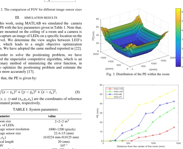
The distribution of PE within the room is illustrated in Fig. 3. Note that, almost no PE is observed at the center of the room but the PE increases significantly when moving towards the
corners of the room. This is due to the camera capturing images of a reduced number of LEDs. As it can be seen from Fig. 3, there is a symmetry in the distribution of the PE. Here, we investigate the effect of FOV on the performance of the proposed system in 1/ 4th of the room.
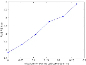
Fig. 4 shows the PE as a function of the distance from the center to the corner of a room for a range of FOVs (i.e., 77, 99, 107, and 179 degrees). Note that, we observe the lowest PE at the center of the room. The PE increases when moving towards the corners of the room. E.g., at a distance of 1 m the increase in PEs are 20, 30, and 40 mm for the FOVs of 77, 99, and 107o, respectively. The lowest PE is achieved for the case with FOV of 179o. Fig. 5 shows the RMS PE against the misalignment of the optical center for x, y and z directions with 41 sample points in a room of 2×2×2 𝑚3. RMS PE increases with the distance away from the optical center, which should be equivalent to the IS’s center in an ideal case. Note that, the RMS PE can also be affected by the pixel resolution of the image sensor, which is shown in Table II, where lower RMS PEs are observed for higher pixel resolutions. Note, here we have assumed that, the light is projected onto the center of a pixel, however this might not be the case in real scenarios and therefore needs investigating as part of the future works.
Fig. 3. Distribution of the PE within the room
Fig. 4. The PE as a function of distance from the center of the room for a range of FOV
Fig. 5. The RMS PE against the misalignment of the optical center for x, y and z directions with 41 sample points.
TABLE II. Impact of pixel resolution on the RMS PE
Pixel resolution RMS PE (cm) 320×480 6.3 510×660 5.5 700×970 4.1 1000×1200 2.85 1280×2000 2.1 IV. CONCLUSIONS
In this paper, the effect of camera parameters including lens distortion, FOV and pixel resolution on the performance of the positioning system was investigated. We showed that, the displacement of the optical center, which should be equivalent to the center of the image sensor in an ideal case, resulted in a relatively large positioning error. In the proposed indoor positioning system, we showed that, increasing the number of LEDs as well as increasing the camera’s field of view, where more LEDs are captured, resulted improved positioning error. Finally, we showed that the accuracy of the positioning is affected by the pixel resolution of the image sensor and higher pixel resolution offers improved lower positioning errors.
REFERENCES
[1] B. Zhu, J. Cheng, Y. Wang, J. Yan, and J. Wang, "Three-Dimensional VLC Positioning Based on Angle Difference of Arrival With Arbitrary Tilting Angle of Receiver," IEEE Journal on Selected Areas in Communications, vol. 36, pp. 8-22, 2018.J. Clerk Maxwell, A Treatise on Electricity and Magnetism, 3rd ed., vol. 2. Oxford: Clarendon, 1892, pp.68–73.
[2] K. Pahlavan, X. Li, and J.-P. Makela, "Indoor geolocation science and technology," IEEE Communications Magazine, vol. 40, pp. 112-118, 2002.
[3] M. S. Rahman, M. M. Haque, and K.-D. Kim, "Indoor positioning by LED visible light communication and image sensors," International Journal of Electrical and Computer Engineering, vol. 1, pp. 161, 2011.
[4] G. Simon, G. Zachár, and G. Vakulya, "Lookup: Robust and Accurate Indoor Localization Using Visible Light Communication," IEEE Transactions on Instrumentation and Measurement, vol. 66, pp. 23372348, 2017.
[5] B. Mungamuru and P. Aarabi, "Enhanced sound localization," IEEE Transactions on Systems, Man, and Cybernetics, Part B (Cybernetics), vol. 34, pp. 1526-1540, 2004.
[6] C. V. Lopes, A. Haghighat, A. Mandal, T. Givargis, and P. Baldi, "Localization of off-the-shelf mobile devices using audible sound: architectures, protocols and performance assessment," ACM SIGMOBILE Mobile Computing and Communications Review, vol. 10, pp. 38-50, 2006.M. Young, The Technical Writer’s Handbook. Mill Valley, CA: University Science, 1989.
[7] B. Lin, Z. Ghassemlooy, C. Lin, X. Tang, Y. Li, and S. Zhang, "An indoor visible light positioning system based on optical camera communications," IEEE Photonics Technology Letters, vol. 29, pp. 579-582, 2017.
[8] A. T. Arafa, "An indoor optical wireless location comparison between an angular receiver and an image receiver," University of British Columbia, 2015.
[9] Y. Hou, S. Xiao, M. Bi, Y. Xue, W. Pan, and W. Hu, "Single LED beacon-based 3-D indoor positioning using off-the-shelf devices," IEEE Photonics Journal, vol. 8, pp. 1-11, 2016.
[10] N. B. Priyantha, A. Chakraborty, and H. Balakrishnan, "The cricket location-support system," in Proceedings of the 6th annual international conference on Mobile computing and networking, 2000, pp. 32-43.
[11] Y. Noh, H. Yamaguchi, and U. Lee, "Infrastructure-free collaborative indoor positioning scheme for time-critical team operations," IEEE Transactions on Systems, Man, and Cybernetics: Systems, 2016, pp.418-432.
[12] Ghassemlooy, Z., et al., IEEE 802.15. 7: Visible Light Communication Standard, in Visible Light Communications. 2017, CRC Press. p. 167-216.
[13] N. U. Hassan, A. Naeem, M. A. Pasha, T. Jadoon, and C. Yuen, "Indoor positioning using visible led lights: A survey," ACM Computing Surveys (CSUR), vol. 48, pp. 20, 2015.
[14] N. B. Hassan, Z. Ghassemlooy, S. Zvanovec, P. Luo, and H. Le-Minh, "Non-line-of-sight 2× N indoor optical camera communications," Applied optics, vol. 57, pp. B144-B149, 2018.
[15] B. Lin, Z. Ghassemlooy, C. Lin, X. Tang, Y. Li, and S. Zhang, "An indoor visible light positioning system based on optical camera communications," IEEE Photonics Technology Letters, vol. 29, pp. 579-582, 2017.
[16] N. B. Hassan, Y. Huang, Z. Shou, Z. Ghassemlooy, A. Sturniolo, S. Zvanovec, et al., "Impact of Camera Lens Aperture and the Light Source Size on Optical Camera Communications," in 2018 11th International Symposium on Communication Systems, Networks & Digital Signal Processing (CSNDSP), 2018, pp. 1-5.C.
[17] M. Abdollahi, A. Isazadeh, and D. Abdollahi, "Imperialist competitive algorithm for solving systems of nonlinear equations," Computers & Mathematics with Applications, vol. 65, pp. 1894-1908, 2013. [18] W.-L. Du and X.-L. Tian, "An automatic image registration evaluation
model on dense feature points by pinhole camera simulation," in Image Processing (ICIP), IEEE International Conference on, 2017, pp. 22592263.
[19] J. Heikkila and O. Silven, "A four-step camera calibration procedure with implicit image correction," in Computer Vision and Pattern Recognition, 1997. Proceedings., 1997 IEEE Computer Society Conference on, 1997, pp. 1106-1112.
[20] J. Weng, P. Cohen, and M. Herniou, "Camera calibration with distortion models and accuracy evaluation," IEEE Transactions on Pattern Analysis & Machine Intelligence, pp. 965-980, 1992. [21] J. L. Parker and P. A. Marvin, "System and method for controlling the
field of view of a camera," ed: Google Patents, 1999.
[22] Y.-C. Cheng, J.-Y. Lin, C.-W. Yi, Y.-C. Tseng, L.-C. Kuo, Y.-J. Yeh, et al., "AR-based positioning for mobile devices," in Parallel Processing Workshops (ICPPW), 2011 40th International Conference on, 2011, pp. 63-70.