© 2017, IRJET | Impact Factor value: 5.181 | ISO 9001:2008 Certified Journal
| Page 3004
Dispersion Compensation Module for WDM -PON at 5 -Gb/s
Downstream with Various Data Modulation
Nidhi Agarwal , Deepak Bansal
Electronics and Communication, Global Institute of Technology, Jaipur,India
Department of Electronics and Communication Engineering, Global Institute of Technology, Jaipur ,India
---***---
ABSTRACT - A Study of Different kind of modulationformat has been discussed to increase the data speed in PON. Wavelength division multiplexing (WDM) is commonly employed to utilize this enormous capacity. A typical transmission system consists of an array of lasers with different wavelengths to generate the optical carriers. Each laser is modulated by an external modulator (e.g. a Mach–Zehnder modulator) to impress the data signal. The Simulation has been done at 5-Gb/s in optical communication system with different transmission distance. The famous of DPSK technique and Dubinary modulation are used for good tolerance to chromatic dispersion. It can achieve the high-spectral efficiency necessary to transmit 10 GB/s data on 50 GHz channel spacing. A duobinary implementation followed due to the higher tolerance to accumulated chromatic dispersion. Further improvements led to the use of differential phase shift keying (DPSK) with interferometric detection. The combination of SMF length 87.5 km and DCF length 12.5 km was chosen for total 100 km fiber length. The BER and Q factor have been used for evaluating the system.
KEY WORDS—Dispersion Compensated Fibers (DCF), Optical Modulation, Wavelength - Division Multiplexing (WDM).
1 . INTRODUCTION
The rapid growth in demand for high-capacity telecommunication links and efficient utilization of fiber bandwidth has resulted in an extraordinary increase in the use of Wavelength Division Multiplexing (WDM) in advanced lightwave networks. The main advantages of having a last mile of optical fiber are many higher bandwidth, longer distances from the central to the subscriber, the more resistance to electromagnetic interference, increased security, reduced signal degradation . Optical fiber communication is method of transmitting information from one place to another by sending pulse of light. To convey information over any distance a communication system is usually required. Fiber optics is a branch of optics which deals with the transmission of light through fiber glass, plastic or other transparent materials. Within a communication system the information transfer is frequently achieved by superimposing the information on to an electromagnetic wave. The Basic need of a communication system is its
information –carrying capacity. The basic optical communication link consists on following four basic components [4]. The optical transmitter is used to generate light signal and modulate information on the signal, the optical fiber is the transmission media of light, the optical receiver receives the transmitted signal and converts it back to the carried information and the optical amplifier is used to extend the transmission distance. In advance optical communication link / system, in addition to the above four devices, more components are required. Optical fibre is used by telecommunication company such a internet, cable television telephone.[3]
2. MODULATION METHODS
The optical power is modulated according to the binary data input signal. Two main types of line codes are usually employed return to zero (RZ) and non-return to zero (NRZ) formats. In RZ formats, the signal amplitude returns to zero at the boundaries of each bit slot, even if consecutive marks are sent whereas in NRZ format the signal amplitude remains on the high level in the case of consecutive marks . Duobinary modulation is a special partial-response code. It can be generated from a binary NRZ signal by delay-and-add coding or low pass filtering . Modulation method was used for transmission rates of up to 5 Gb/s on/off keying or OOK for short. An important advantage of using the coherent detection technique is that both the amplitude and phase of the received optical signal can be detected and measure. [1]
(a) BPSK (Binary phase shift keying ) : BPSK is the most efficient of the three digital modulation. Binary phase shift keying is used for high rates . In BPSK phase of sinusoidal carrier is changed according to the data bit to be transmitted. NRZ signal is used to represent the digital data coming from the digital source. Binary ‘1’is to be transmitted +1. and Binary ‘0’ is to be transmitted -1. Phase change is usually a fixed phase shift in the transmitted.
© 2017, IRJET | Impact Factor value: 5.181 | ISO 9001:2008 Certified Journal
| Page 3005
absence of a phase change DPSK the phase of the modulated signal is shifted relative to the previous signal element. The signal phase follows the high or low state of the previous element. This DPSK technique doesn’t need a reference oscillator. DPSK encodes two distinct signals, that is the carrier and the modulating signal with 180° phase shift each. Symbol ‘0’ may be used to represent transition in a given binary sequence and symbol ‘1’ to indicate no transition [5].
(c) OOK (on-off keying): ON-OFF keying (OOK) is simplest digital modulation technique that represents
digital data. OOK is more spectrally
efficient than frequency-shift keying but more sensitive
to noise when using a regenerative receiver or a poorly
implemented super heterodyne receive. Its
return-to-zero (RZ) version improves the clock recovery by making the signal return to zero in the middle of the bit period so a constant stream of one would be represented by an alternating signal . The bit stream is also scrambled to avoid long streams of zeroes. There is only one unit energy carrier and It is switched on or off depend upon the input binary sequence. Higher amplitude is represented by logic 0. And lower amplitude is represented by logic 1 [2].
* Dispersion compensation fiber:
Dispersion compensation fiber is used in many countries, existing million of kilometer of single mode fiber in undergoes duct operate at 1.3 micro meters. A short length of DCF can be used in conjunction with the 1.3 micrometer optimized fiber length so as to have much lower total dispersion over the entire length. If these fiber are operated at 1.55 micrometer, there will be a significant residual dispersion.[6]
3. SIMULATION SET UP
In optical long-haul transmission networks mainly coherent continuous-wave (CW) lasers are used. A CW signal produced by Distributed feedback laser (DFB) is a laser diode at wavelength of 193.1 nm. Semiconductor lasers are by far the most popular light source for optical communication systems . Semiconductor lasers are compact and usually only a few hundred micrometers in size Frequently used are DFB (distributed feedback) lasers, which are made of InGaAsP (indium gallium arsenide phosphide) for the required wavelength range. DFB lasers can be tuned by varying the forward-bias current, which changes the refractive index. However, changing the bias current also changes the output power of the device and makes this technique unsuitable Lasers are usually not directly modulated to suppress the chirping of the emission wavelength, which is especially detrimental at higher bit rates . Instead, external modulators are used e.g. optical Mach–Zehnder modulators MZMs can be implemented in Lithium Niobate (LiNbO3), Gallium Arsenide (GaAs) or Indium Phosphide (InP) the high bandwidth of the fiber can be utilized efficiently by employing a multitude of
transmitters using different wavelengths. This
transmission scheme is called wavelength division
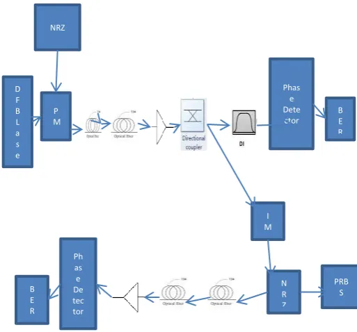
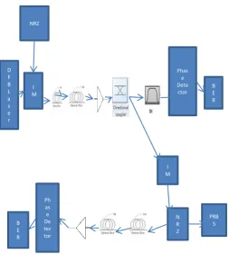
[image:2.595.313.578.268.498.2]multiplexing (WDM). Simulation has been set up on 5-Gb/s use RZ and NRZ Duo binary modulation. the optical signal is attenuated by the optical fiber and other components such as multiplexers and couplers, it has to be re-amplified after some distance. Instead also so-called regenerators may be deployed, which receive the signal and retransmit it again Fig.[1-6]. Amplifer is a electronics device that can increase the power of signal —a delay line interferometer (DI) is inserted in the optical path at the receiver to convert the differential phase modulation into intensity modulation A DI can be used to convert the differential phase modulation into intensity modulation. Same process of the Intensity modulation and the Amplifier work on 20dB gain. Delay Infer meter is 0.2 ns is used. Various wavelength work on SMF and DCF.
Fig.1. Manchester DPSK with 5-Gb/s downstream
Fig .2. NRZ DPSK with 5-Gb/s downstream
D F B L a s e r P M Manche ster Phase Detec
tor B
[image:2.595.313.570.539.778.2]© 2017, IRJET | Impact Factor value: 5.181 | ISO 9001:2008 Certified Journal
| Page 3006
Fig. .3. Manchester OOK with 5-Gb/s downstream
Fig. 4. NRZ OOK with 5-Gb/s downstream
Fiber section : The optical signal is fed into the fiber. Two segment have been used SMF of length L1 km and DCF L2 km in entirely fiber 100 km. L1 and L2 are used variables. Table [1-5].
Table 1.
Table 2.
Table 3.
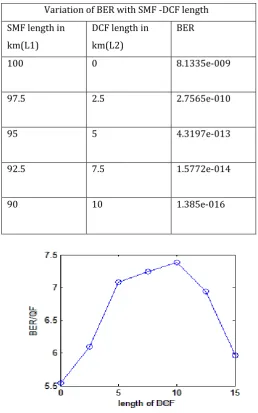
Variation of BER with SMF -DCF length
SMF length in km(L1)
DCF length in km(L2) BER
100 0 5.0119e-010
97.5 2.5 8.0432e-012
95 5 9.9871e-014
92.5 7.5 7.7079e-015
90 10 4.4199e-012
87.5 12.5 8.3088e-015
85 15 9.91e-014
82.5 17.5 9.90862e-013
Variation of BER with SMF –DCF length SMF length in
km(L1)
DCF length in km(L2)
BER
100 0 4.5933e-010
97.5 2.5 6.955e-011
95 5 1.557e-013
92.5 7.5 2.71194e-014
90 10 7.0262e-014
87.5 12.5 4.624e-017
Variation of BER with SMF –DCF length SMF length in
km(L1)
DCF length in km(L2)
BER
100 0 5.4651e-007
97.5 2.5 5.651e-008
95 5 2.2559e-009
92.5 7.5 4.718e-011
90 10 2.52639e-010
87.5 12.5 1.0307e-009
85 15 3.6240e-010
D F B L a s e r
I M Manc heste r
Phas e Dete ctor
B E R
I M
PRB S N
R Z Ph
as e De tec tor B
E R
D F B L a s e r
I M NRZ
Phas e Dete
ctor B E R
I M
PRB S N
R Z Ph
as e De tec tor B
[image:3.595.36.290.390.671.2]© 2017, IRJET | Impact Factor value: 5.181 | ISO 9001:2008 Certified Journal
| Page 3007
Table 4
Fig.5 Q factor vs receive power for downstream signal DPSK use Manchester withDCF
[image:4.595.29.288.106.520.2]Fig.6 Q factor vs received power for downstream DPSK use NRZ with DCF
Fig.7 Q factor vs receive power for downstream IM use Manchester with DCF
Fig.8 Q factor vs receive power for downstream signal IM use NRZ with DCF
4. RESULT CONCLUSION
The performance of the system is evaluated using the parameters, BER and Q factor, with pre, post and symmetrical compensation techniques using DCF at various link lengths .The main advantage compared to NRZ-OOK is a 3 dB receiver sensitivity improvement, which can be intuitively understood from the increased symbol spacing for DPSK compared to OOK for fixed average optical power This signal format furthermore shows better behavior regarding signal distortions due to fiber nonlinearities especially excellent resilience to cross-phase modulation . NRZ can be travelled till longer distance without DCF , Therefore NRZ is better than Manchester. NRZ and Manchester are worked on various wavelength. . Better performance is shown when a combination of SMF length 87.5 km and DCF length 12.5 km was chosen for total 100 km fiber length.
Variation of BER with SMF -DCF length SMF length in
km(L1)
DCF length in km(L2)
BER
100 0 8.1335e-009
97.5 2.5 2.7565e-010
95 5 4.3197e-013
92.5 7.5 1.5772e-014
[image:4.595.338.547.308.479.2] [image:4.595.57.278.571.739.2]© 2017, IRJET | Impact Factor value: 5.181 | ISO 9001:2008 Certified Journal
| Page 3008
REFERENCE[1] “Comparison of RZ Versus NRZ Pulse Shapes for Optical Duobinary Transmission”, Cheng-Chung Chien and Ilya Lyubomirsky, Journal Of Lightwave Technology, Vol. 25, No. 10, October 2007.
[2] “Advanced Modulation Formats for Ultra-Dense
Wavelength Division Multiplexing”, Dr. Ilya Lyubomirsky 2005.
[3] Kuschnerov, M., Hauske, F.N., Piyawanno, K., Spinnler, B., Alfiad, M.S., Napoli, A., Lankl, B.: DSP for coherent single-carrier receivers. IEEE/OSA J. Lightw. Technol. 27(16), 3614–3622 (2009)
[4] M. I. Hayee and A. E. Willner, “Pre- and post-compensation of dispersion and nonlinearities in 10-Gb/s WDM systems”, IEEE Photon. Tech. Lett. 9, pp.
1271, 1997.
[5] Design Performance of High Speed Optical Fiber WDM System with Optimally Placed DCF for Dispersion Compensation. Yadav, Mulayam, et al. 20, s.l. : Foundation of Computer Science, 2015, International Journal of Computer Applications, Vol. 122.