© 2017, IRJET | Impact Factor value: 5.181 | ISO 9001:2008 Certified Journal
| Page 1966
MULTI-FUNCTIONED FARMING VEHICLE USING LOCAL POSITIONING
SYSTEM AND ADVANCED PATH PLANNING ALGORITHMS
Aditya M. Belekar
1, Somesh P. Bakshi
2, Vinayak V. Patil
3, Oorja R.S. Shrivastava
4,
Rushikesh R. Chavan
5, Sumeet S. Gavaskar
61
Dept. of Mechanical Engineering, PCET’s Pimpri Chinchwad College of Engineering, Pune, Maharashtra, India.
2
Dept. of Electronics & TC Engineering, PCET’s Pimpri Chinchwad College of Engineering, Pune, India.
3
Dept. of Mechanical Engineering, PCET’s Pimpri Chinchwad College of Engineering, Pune, India.
4
Dept. of Computer Engineering, PCET’s Pimpri Chinchwad College of Engineering, Pune, India.
5
Dept. of Mechanical Engineering, G.H.Raisoni College of Engineering and Management, Pune, India.
6
Dept. of Mechanical Engineering, Pad.D.Y.Patil Institute of Engineering Management and Research, Pune, India.
---***---Abstract - The multi-functioned farming vehicle using local
positioning system and advanced path planning algorithms should be used to improve the issues in farming. The vehicle uses local positioning system with four ultrasonic sensors at the extreme ends that is at the corner of farm which detects boundary of farm. Vehicle is having one sensor on it which shows its location. Vehicle is run by advanced path planning algorithms implemented in LabVIEW software and operated through dc motor. In farm there are six columns of different farming techniques like seeding, spraying, cutting and collecting of crops. Vehicle is having interchangeability of tools according to different techniques of farming. Work estimation is done by parameters like number of seeds, ml of water, weight of crop collected .The obstacle is detected by vehicle through ultrasonic sensors. Its indication is given by alarm of sound or light that is LED. Vehicle stops after obstacle detection and after finding resolved path it starts and run accordingly. Thus multi-functionality, LPS technology and obstacle detection by path planning algorithms used in vehicle makes it compact device for farming.
Key Words: local positioning system, ultrasonic sensors, LabVIEW software, work estimation, LED, obstacle detection
1. INTRODUCTION
The agricultural rate in India’s economy is decreasing. Poor yields are obtained due to natural calamities, improper management during agriculture practices and failure of operation due to insufficient field information for effective path planning. Tremendous amount of energy loss due to improper working of costly and time consuming individual farming equipment. The multi-tasking farming vehicle using local positioning system and advanced path planning algorithms should be used to improve the issues. Suicide rates in India are increasing rapidly. In 1995, suicides per year in India were 10500-10700, now in 2016-17 it is increased up to 14500-15000. Agriculture rate of India is also decreasing year by year. India’s GDP from agriculture was 5460 INR Billion in 2014, now it is decreased to almost 4300 INR Billion in 2017 which is very less as compared to
other countries. Tremendous amount of energy is lost by different farming vehicles and in various processes. In India, Animals and manual labour work is used mostly farming. The challenge is to provide customers multi-functioned vehicle which can be cheap and easily available. Vehicle should satisfy all needs of farmer .The vehicle should obtain goals such as decreasing suicide rate, increasing agriculture rate, higher yields and energy utilization. It should reduce animal and labour work through its multi-functionality.
2. SYSTEM ARCHITECTURE (Considering Prototype
of System)
System architecture includes physical structure of vehicle and farm, detection by sensors, path planning, interchangeability of tools, obstacle detection and work estimation.
2.1 Physical structure of vehicle
Vehicle dimensions: Length = 0.5 m Width = 0.3 m Height = 0.25 m
Total weight of vehicle = Weight of chassis + Weight of tools
= 8 kg + 4 kg = 12 kg
Motor: 12 volt dc motor is used for running and all functions.
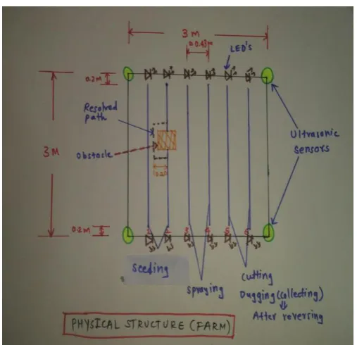
2.2 Physical structure of farm
Farming area = 3 m * 3 m = 9 m2
Six columns for various operations to be performed as follows:
Column 1 & 2: Seeding and obstacle detection with processing in resolved path
Column 3 & 4: Spraying
© 2017, IRJET | Impact Factor value: 5.181 | ISO 9001:2008 Certified Journal
| Page 1967
Total LED’s = 2 LED’s per column= 2 * 6 = 12
[image:2.595.35.289.143.388.2] Distance between two columns = 0.43 m (approx.)
Fig – 1: Physical structure of farm
2.3 Detection by sensors
Total ultrasonic sensors = At the corners of farm + On the vehicle
= 4+1 = 5 Maximum range = 3 m
2.4 Interchangeability of tools
Tools like cutter, sprayer, seeding equipment, bucket, spraying tank are mounted on vehicle according to operation to be performed.
Fig – 2: Farming tools
2.5 Obstacle detection and processing in resolved Path
o Taking Square / Rectangular shaped obstacle
o Obstacle Dimensions = 0.15 m * 0.15 m = 0.0225 m2
o Resolved path = 0.20 m distance covered per rotation in linear direction
2.6 Work estimation
Work estimation is done by seeds bowed, pesticide sprayed, weight of crop
Pesticide Capacity = 2 litre = 1 litre per line = 100 ml per crop
Seeding Capacity = 20 seeds = 10 seeds per line = 1 seed per 0.26 m
Weighing Capacity = 3 kg = 1.5 kg per line
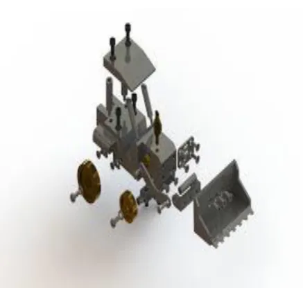
[image:2.595.314.553.407.513.2]3. DESIGN OF VEHICLE
[image:2.595.36.560.570.788.2]Fig – 3: Inclined view showing front body with tools
© 2017, IRJET | Impact Factor value: 5.181 | ISO 9001:2008 Certified Journal
| Page 1968
Fig – 5: Exploded view of vehicle4. HARDWARE AND SOFTWARE (Considering
Prototype of System)
4.1 Hardware
No. Component Model No. Specifications
1 Chassis 4WD All Terrain Chassis
10 mm allowance for mounting of PCB’s sensors, brass fitting, nickel plated suspension springs
2 Motor - Operating voltage-12 volts
3 Motor Controller Circuit a. Diode b. n-channel enhance ment mode MOSFET p-channel enhancement mode MOSFET 1N4001 ZVN2110A IRF510 ZVP2110A General Purpose n-channel n-channel p-channel 4 Actuators SH-T2551Z o Type: Solenoidal pull push type
o Operating Voltage: 12 volts
Power: 10 watt
5 Ultrasonic
Sensor Series 7000 Size : 2 cm to 3 cm
6 Battery Battery pack 41135
1x 10-cell AA NiMH
Other hardware parts
Cutting Tool Bucket Sprayer Spraying Tank Seeding Device Wheels
Required parts of vehicle
4.2 SOFTWARE
I. LABVIEW 2017 II. myRIO toolkit 2017 III. Real Time Module 2017 IV. JKI State Machine
5. IMPLEMENTATION
I. At start, vehicle is at one of the corner of farm leaving 0.20 m distance from boundary. Ultrasonic sensors are mounted at the corner of farm and one on the vehicle. Before starting of vehicle system detects vehicle location and also boundary detection is done by local positioning system.
II. Vehicle is operated by DC motor and path is given by advanced path planning algorithms in LabVIEW.
III. In column 1, seeding operation is done by using seeding tool. In which vehicle bows 1 seed per 0.26 m distance throughout the column. Vehicle covers almost 2.6 m distance and rotates for going in next column. If vehicle goes in clearance area (i.e. >2.6 m) then LED glows for indicating incorrect path.
© 2017, IRJET | Impact Factor value: 5.181 | ISO 9001:2008 Certified Journal
| Page 1969
V. In column 3 & 4, spraying operation isexecuted by using sprayer and tank filled with pesticide. In this operation vehicle sprays 100 ml of pesticide per 0.26 m distance. It uses total 2 litre of pesticide i.e. 1 litre per column. By LED sensing rotation is done as before.
VI. In column 5 & 6, cutting operation is performed by using cutter. For that required RPM are set for the cutter.
VII. After cutting operation, collection of crops is done by bucket. For that vehicle reverses its direction and moves in column 6 for collection. Vehicle cut 1.5 kg of crop per column by using bucket.
VIII. Work estimation is done by considering number of seeds bowed per column, ml of pesticide sprayed per column and by weight of crop cut per column. It is done after each operation simultaneously.
6. CONNECTION DIAGRAM
[image:4.595.52.556.89.810.2]This wiring or connection diagram shows how hardware can be connected to myRIO toolkit for actual working of vehicle by connecting different wires.
Fig – 6: Connection diagram
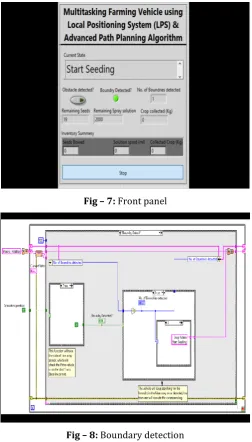
[image:4.595.308.561.109.552.2]7. IMPLEMENTATION IN LABVIEW (JKI STATE MACHINE)
Fig – 7: Front panel
[image:4.595.38.559.399.765.2]Fig – 8: Boundary detection
[image:4.595.40.312.423.722.2]© 2017, IRJET | Impact Factor value: 5.181 | ISO 9001:2008 Certified Journal
| Page 1970
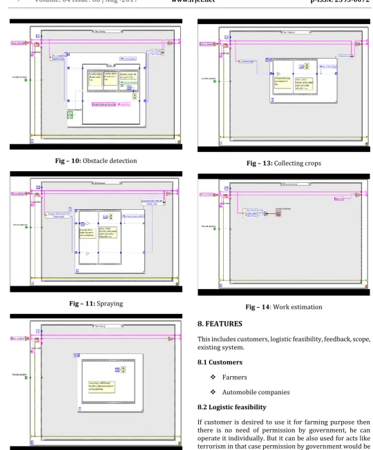
Fig – 10: Obstacle detectionFig – 11: Spraying
Fig – 12: Crop cutting
[image:5.595.22.563.62.715.2]Fig – 13: Collecting crops
Fig – 14: Work estimation
8. FEATURES
This includes customers, logistic feasibility, feedback, scope, existing system.
8.1 Customers
Farmers
Automobile companies
8.2 Logistic feasibility
© 2017, IRJET | Impact Factor value: 5.181 | ISO 9001:2008 Certified Journal
| Page 1971
8.3 FeedbackFeedback concludes that it is helpful to the farmers whom have less manpower, having big farms. Farmers can easily take care of their farm without actually going into the farm. For farmers who live little away from their field it is beneficial for them.
8.4 Scope
Decrease in suicide rate
Energy utilization
Higher yields
Increment in agriculture rate
Vehicle using LPS technology
8.5 Existing system
o There exists Kalman’s filtering technique which uses supplementary measurements like odometry and altitude for improving accuracy of GPS-receiver which is not so accurate. It also uses GPS technique which is not affordable to everyone.
o There exists robots which can analyze moisture content of soil and parameters like that for farming operations. This system also uses GPS in it.
9. CONCLUSION
The study concludes following points:
Vehicles or devices with similar type may be available but either they are not multi-functioned or they are using GPS for detection.
Vehicle uses local positioning system for detection and advanced path planning algorithms in LabVIEW software which are easy to use and affordable.
System includes obstacle detection and path planning in resolved path which is very important considering different farming conditions.
Vehicle is less expensive, easily available and multi-functioned so useful for farmers and respective customer.
REFERENCES
[1] Chong Jin Ong, E. G. Gilbert ‘Robot Path Planning with Pentration Growth Distance’ published in IEEE Aug 2002, INSPEC Accession Number: 4829386.
[2] Zeping Fang, Jianmin Duan ‘Obstacle detection for intelligent vehicle based on LabVIEW laser measurement system’ published in IEEE Jan 2014, INSPEC Accession Number: 14059963.
[3] Krzysztof W. Kolodziej, Johan Hjelm ‘Local Positioning System’ for understanding LPS applications and services.
[4] Hans-petter Halvorsen ‘ myRIO Overview’ for understanding connections of LabVIEW algorithms with myRIO toolkit.
[5] Jeffrey Travis, Jim Kring ‘LabVIEW for Everyone’ for understanding concepts of LabVIEW and JKI State Machine.