MEMORY REQUIREMENTS FOR HARDWARE IMPLEMENTATION OF
THE H.264 DECODER MODULES
Karthikeyan. C1 and Rangachar2
1Department of Electronics and Communication Engineering, MNM Jain Engineering College, Chennai, India 2Dean for School of Electrical Science, Hindustan University, Chennai, India
E-Mail: [email protected]
ABSTRACT
To address the increasing demand for higher resolution and frame rates, processing speed (i.e. performance) and area cost need to be considered in the development of next generation video coding. Context-based adaptive binary arithmetic coding (CABAC) is the major entropy-coding algorithm employed in H.264/AVC. In this paper, subinterval reordering is proposed for the arithmetic decoder to increase the processing speed and to lower the frequency of memory access. Modification of the motion vector difference (MVD) context selection is proposed to reduce memory requirements and speed up the memory access. These above two methods and architecture optimizations are non-standard compliant and this proposed work is incorporated using buffers and registers for temporary storage and processing of the data. The speed of operation is improved by more than 50% with respect to normal operation.
Keywords: H.264, Video Codec, CABAC, MVD.
1. INTRODUCTION
H.264/AVC [1] has been the state of the art video compression standard of the ITU-T Video Coding Experts Group and ISO/IEC Moving Picture Experts Group (MPEG) in current video applications. It promises to outperform the earlier MPEG-4 and H.263 standard, employing many better innovative technologies such as multiple reference frame, variable block size motion estimation, in-loop de-blocking filter and context-based adaptive binary arithmetic decoding. H.264/AVC system can save the bit-rate up to 50% compared to the previous video standard such as H.263 and MPEG-4 under the same quality. Traditionally, the focus of video coding development has been primarily on improving coding efficiency. However, as processing speed requirements and area cost continue to rise due to growing resolution and frame rate demands, it is important to address the architecture implications of the video coding algorithms. The standard specifies two types of entropy coding algorithm: CABAC and Context-based Adaptive Variable Length Coding (CAVLC). CABAC entails an access frequency increase from 25% to 30% with bit rate reduction up to 16% [2], therefore, researches on CABAC hardware implementation have been done in recent years [3, 4, 5]. CABAC achieves high compression ratio but bringing greater complexity and cost in implementation. Because of frequent memory (ROM and RAM) access, it spends large time in CABAC decoding process. Although the DSP implementation of CABAC decoder decreases the working time, it also needs 30~40 cycles to decoding a bit. So it is not an appropriate choice for real-time CABAC decoding applications, however, FPGA (or ASIC), as a good hardware implementation manner, is being increasingly used in this field.
Algorithm in [3] illustrates a solution to class all SEs to two categories according to their occurring frequency to improve the decoding efficiency. The architecture for CABAC decoding in [4] is claimed the first hardware architecture in the open literature. Architecture in [5] handles all the context information needed by CABAC and rate distortion optimization together. However, in [3], only the bin decoding efficiency is emphasized and improved. Prediction-based pipelined architectures [6, 7] have been proposed to achieve high-throughput. Some methods, such as syntax element prediction, redundant circuits, and forwarding techniques, can be adopted to void pipeline stalls. However, the design of [6] does not utilize the memory bandwidth well and each pipeline stage contains at least one memory access, which greatly increases the frequency of memory access. Moreover, the decoder has to load two context models and store one in every cycle. Thus, memory access conflicts occur frequently and two dual-port static random access memory (SRAM) devices have to be used to solve them, which increases the cost of hardware. Although the design of [7] can decode in high-rate mode, almost all context models are stored on chips and both dual-port SRAM and registers are used, which impose heavy hardware costs on the gate count. [8] proposed an area-efficient architecture, but only a single-bin engine is used and the throughput is low.
reorganized the context table into 29 groups to ensure that each group is loaded only once during the decoding process of one MB, and have adopted a 112-bit circular buffer to cache the context models. Both of these changes reduce memory bandwidth dramatically. Furthermore, we have divided the decode decision engine into two half branches: the most possible symbol (MPS) decode decision branch and the least possible symbol (LPS) decode decision branch. The MPS branch is much simpler than the LPS branch. Therefore, two MPS branches are sophisticatedly concatenated to decode two bins in one cycle and the critical path is kept almost the same as that of the decode decision engine.
2. CABAC DECODER ARCHITECTURE
In this we discuss about the building block for CABAC decoder and the flow chart for the decoder algorithm. In the encoder side the syntax element (SE) of the H.264/AVC will be transferred into the bits of binary code called ‘bin’ except flag type of SE. The bin string is decoded by two levels of decoder namely binary arithmetic decoder and de-binarization. The binary arithmetic decoders have three different types such as regular, bypass and terminal decoding processes. The basic block diagram is shown in Figure-1.
Figure-1. Block diagram of CABAC decoding flow.
At the beginning, when a new slice data occur the probabilities of the context model has to be initialized by the context model initial table. The 459 kinds of context model values are calculated and written to the context model RAM. The bitstream module provides input bitstream to the decoder and 459 context models are stored in mxn ROM. To simplify the calculation range of least probable symbol (rLPS) is stored in ROM. The core decoder module consists of two regular decoding engines and two bypass decoding process. The cache memory is used in between the RAM and core decoding unit to reduce memory access and it saves the decoding cycle evidently. The first decoding flow is the arithmetic decoder which is the first stage of decoding one syntax element. It produces the bin value depending on the current range (codlRange) and the current value (codlOffset). The second decoding flow is the binarization engine. It reads the bin values to judge if the bin string forms the meaningful data. If not, the binarization engine requests the arithmetic decoder to decode one bin again
and re-judges the bin string until identifying the value of the current syntax element.
There are four kinds of SEs including slice data, MB layer, (sub) MB pred and residual block cabac. The Slice data and MB layer produce once time per macro block. (sub) MB pred and residual block cabac are produced according to block size. Therefore, we may often change our decoding order because of variable macro block type.
In slice data, we have three syntax elements such as mb_skip_flag, mb_field_decoding_flag and end_of_slice_flag. The mb_field_decoding_flag is used to recognize frame and field MB, and we produce once per MB pair. The end_of_slice_flag is always symbolized final syntax element of MB, and the slice will be finished when end_of_slice_flag equal to one. Besides, if the mb_skip_flag equal to one, we directly jump to end_of_slice_flag and skip this MB.
In MB layer, we have four syntax elements such
current block in which block size by mb_type and transform_size_8x8_flag. The mb_qp_delta is a parameter for inverse-quantization, and coded_block_pattern are represented zero distribution of residual block.
After decoding value of mb_type, we can depend on block size to judge the following status which will be mb_pred or sub_mb_pred. If we decode in sub_mb_pred, we may produce sub_mb_type to recognize sub-block size. And then, we may decode one or more predictor modes such as prev_intra NxN_pred_mode_flag, rem_intra NxN_pred_mode, intra_chroma_pred_mode, ref_idx_lX and mvd_lX for Intra or Inter predictor. (Nא4, 8; X א0, 1)
Finally, we would decode the coefficient (coeff.) block in residual block cabac. The coeff. block size can be categorized into 4x4 and 8x8. So, we can get sixteen or four coeff. blocks in macro block.
The coded_block_pattern may describe situation of each 8x8 block, and the coded_block_flag may describe that current 4x4 block contains all zero or not. After that significant_coeff_flag and last_significant_coeff_flag will scan all coeff. positions, and the coeff_abs_level_minusl and coeff_sign_flag produce the value of coeff. position which isn’t equal to zero.
2.1 Design challenges
However, the bottleneck of CABAC decoder design is the throughput for the H.264/AVC system. The next range and value depend on current range and offset, and the table is controlled by outputted bin. So, it has notably strong data dependency to restrict throughput. The RAM-based context model scheduling for fetching and write-back becomes important issue. The table-base CABAC reduce complexity significantly, but it also raises large table which have to include memory.
2.2 Cabac decoding flow
When CABAC decoder is invoked, it schedules the timing related to the context model of reading-to and writing-back and selecting the arithmetic decoding flows and binarization flows. Figure-10 shows the finite state machine (FSM) of the traditional CABAC decoding flow [9]. The first state (state 0) is the stand-by state. The decoder waits for the request of the syntax element parser until activating the CABAC decoder system, and jumps to state 1. State 1 is required to check the type of AD. If it is the regular decoding, the binarization reads the neighbour information from the SRAM, and generates the context model index and reads the context model form the context model. And then, FSM jumps to state 2.
Figure-2. Traditional CABAC decoding flow.
State 2 is a binary tree where we have defined in Section 2.1.2. Based on the binindex (binIdx), the binstring is compared with the binary tree. If binstring can’t find the mapped binary, the binarization engine increases binIdx and requests AD producing the next bin value to map again until the mapped binary and the suitable value of syntax element instate 3. If it finds the
mapped binary value, the value of binIdx is initialized as “0” and waits for the request of the next syntax element
2.3 Context model index calculating flow
arithmetic decoder, we have to prepare the 459 locations of the context model to record all decoding results in high profile.
ctxIdx=ctxIdxOffset + ctxIdxInc (1)
ctxIdx=ctxIdxOffset + ctxIdxBlockCatOffset + ctxIdxInc (2)
It divides into two kinds of the context model index (ctxIdx) methods to allocate the context model. (Eq. 1 is one of the index methods. Besides residual data decoding, the context model index is equal to the sum of ctxIdxOffset and ctxIdxInc. (Eq. 2 is the index method for residual data decoding). The equation contains ctxIdxBlockCatOffset term which is depending on the type of coefficient block.
3. MEMORY SYSTEM REQUIREMENT
In order to improve the decoding efficiency the storage structures of Context models RAM, rLPS_ROM module and storage of neighbouring pixels are modified. These memories are closely related to the Core decoder module during decoding process.
3.1 Proposed context models RAM structure
The first clock cycle is used to read the corresponding context model from the Context Models RAM and one more clock cycle is required to write back the updated context model while decoding a bin. Due to read and write operation there is needed for at least two cycles to maintain one context model and it will reduce the speed of operation. It is necessary to insert a cache between the Core decoder module and the Context models RAM module, so that fetching models and renewing models are implemented in the cache. If the cache is organized as inner register group, the Core decoder module does not consume any cycle while accessing the Context renewing cache module.
Considering the cache characteristics, we divide context models into 25 groups according to the order of being called. In this group only one group contains 44
context models and others contain maximum of 14 context models. It is required to organize 44x7 bit registers for the cache memory. In this architecture the entire 459 context models are stored in 64 x105 bits RAM. In our design each row contains 15 context models (105 bits) and it is called one group. In each group some of them contain less than 15 context models. The only group with 44 context models are placed in three rows and it requires three clocks cycle to read and three clock cycles to write. The other group can be loaded and written back in one cycle.
3.2 Range of least probable symbol Read only memory During arithmetic decoding there is a need for look up fixed tables namely 2 Range of least probable symbol Read only memory (rLPS_ROM) and other is to get transIdxLPS that is the updated pStateIdx (probability state index).
For low complexity the subinterval range values of rLPS are pre-stored in a fixed table of 4x64 normally. The values of pStateIdx and transIdxLPS are also stored in a fixed table. During encoding each bin it is required to look up the above tables and update the pStateIdx value. The above tables are stored in ROM and to access a ROM it costs one cycle time. During decoding process consumes two cycles to look up two fixed tables.
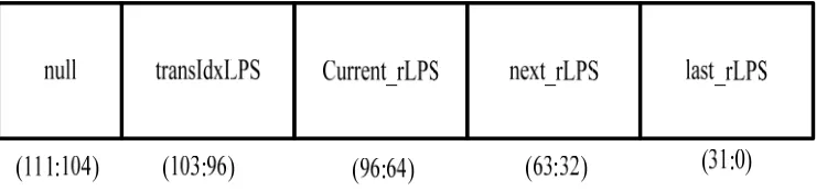
In order to speed up the operation we are proposing two tables into one table and the width of the Table is 112 bits. The storage structure is shown below and it contains 64x112 bits.
The width of current rLPS, next rLPS and last rLPS is 32 bits each. The variable transIdxLPS has 8 bits representing the renewed pStateIdx of the least probable symbol (LPS). The variable transIdxMPS is not stored in the table and it can be calculated as follows:
If(pStateIdx!=62 && pStateIdx!=63) transIdxMPS=pstateIdx+1;
else
[image:4.612.122.497.580.667.2]transIdxMPS=pstateIdx end if;
The main objective of the above storage requirements are
a) prefetching mechanism of rLPS for the next bin b) In order to have parallelism rLPS values to two
regular engines
Using this approach, it does not cost any cycle to load the rLPS and the renewed pStateIdx from the rLPS_ROM. when the ctxIdxInc value of current bin is either equal to the former bin or one greater than former bin’s in most of decoding process. Therefore the structure characteristic of the rLPS_ROM module is beneficial to improve decoding efficiency.
3.3 Neighbouring pixel value storage
The other parts to be considered is neighbour information storage. When we access data from external memory for the neighbour information will increase the latency. When we access the data through system bus, the latency will exceed the timing requirement. This is due to system clock; other modules occupy the memory bandwidth etc. This leads to problem when we decode in real time application even though less storage is used.
Figure-4. Neighbouring pixel requirement.
In this work we are proposing a method to store row of MB neighbour information in an internal memory. This will require about 20 Kbits SRAM for CABAC decoder. The best way for the above problem to reduce the stored neighbour information. The most efficient way to pre-calculate syntax element for neighbour macroblock and provide a concentrated buffer to reduce redundant hardware cost.
To store one motion vector difference (mvd) we require 10 bits. Each MB has 16 mvd for worst case. To calculate ctxIdx for mvd, we need left and top neighbour mvd. To calculate ctxIdxInc we are not using entire 10 bits for the most of the cases. From the analysis we find the most of mvd can be represented by two bits only. By this approach we can reduce each mvd from 10 to 2 bits. To store extra mvd we use extra 5 bits. To access neighbour mvd, first 2 bits for each mvd and several extra mvd from memory are accessed. By this method we can reduce about 65 to 70 % storage area.
Figure-5. In the end of top and left buffer (b) After decoding MB process.
When we decode first bin of SE, we are accessing the same SE at the neighbour, which is present in current MB or neighbour MB. For this we require two buffers one buffer is used to store the data from neighbour MB and the other to store the current MB. Both of them occupy largest buffers, so we are combine these two buffers to raise the buffer efficiency.
The neighbour data will not available always from memory for variable block size. During decoding, the neighbour block may be changed from neighbour to current MB. By this way we can reuse the buffer for storage. At the beginning, current block 0, the neighbour
information left and top buffer are read. The buffer is cleared and updated by the pre-calculated information.
RESULT AND DISCUSSIONS
The motion vector storage and calculation of the current data is updated from the neighbouring vector. The above memory requirement and current data updation are written in VHDL code. The simulation result is shown in Figure-6 and device utilization summery is shown in Table-1.
Figure-6. Simulation result of mvd memory.
Figure-7. RTL View mvd memory.
Table-1. Device utilization summary.
S. No. Name of logic Used Available Utilization in % 1 Number of slice Registers 114 69120 0%
2 Number of slice LUTs 147 69120 0%
3 Number of fully used LUT-FF pairs 77 191 40%
4 Number of bonded IOBs 58 680 8%
The simulation result of context ram shown in Figure-8 after writing code for the same using VHDL. The synthesis result and RTL view is shown in Figure-9.
Figure-8. Simulation result of context ram.
Figure-9. RTL view of context ram.
Table-2. Device utilization summary.
S. No. Name of logic Used Available Utilization in % 1 Number of slice Registers 168 69120 0%
2 Number of slice LUTs 7 69120 0%
3 Number of BUFG/BUFGCTRLs 1 32 3%
4 Number of bonded IOBs 349 680 51%
Maximum Frequency of operation: 263.435MHz
The rLPS memory requirement is coded in VHDL and the simulation and synthesis report is shown in Figure 10 and 11.
Figure- 11. RTL view.
Selected Device: 5vlx110tff1738-3
Table-3. Device utilization summary.
S. No. Name of logic Used Available Utilization in % 1 Number of slice Registers 58 69120 0%
2 Number of slice LUTs 8 69120 0%
3 BUFG/BUFGCTRLs Number of 1 32 3%
4 Number of bonded IOBs 120 680 17%
Maximum Frequency of operation: 422.476MHz
CONCLUSIONS
This paper presents the memory requirement and the architecture for the same. We have presented a new reorganized decode decision engine with look-ahead ctxIdx calculation logic to improve performance. Using this optimal memory requirement and accessing the data which are required for the next update is stored in cache inorder to improve the speed of operation. Using this method there will be increase processing speed by 14 to 22% and reduce memory size by 50%. It demonstrates the benefits of accounting for implementation cost when designing video coding algorithms. We recommend that this approach be extended to the rest of the video codec to maximize processing speed and minimize area cost, while
delivering high coding efficiency in the next generation video coding standard. The future work of this project is further reduction of external memory and implementing this architecture in ASIC environment.
REFERENCES
[1] 2007. Joint Video Team (JVT) of ISO/IEC MPEG and ITU-T VCEG. Joint Draft ITU-T Rec. H.264 | ISO/IEC 14496-10/Amd.3 Scalable video coding.
Complexity and performance analysis on a tool by tool basis. In IEEE Packet Video.
[3] Wei Yu, Yun He. 2005. A high performance CABAC decoding architecture. IEEE Transaction on Consumer Electronics. 51(4).
[4] Jian-Wen Chen, Cheng-Ru Chang, Youn-Long Lin. 2005. A Hardware Accelerator for Context-Based Adaptive Binary Arithmetic Decoding in H.264/AVC. Circuits and Systems. ISCAS, IEEE International Symposium on. 23-26, Vol. 5: 4525-4528.
[5] Nunez-Yanez Y.L., Chouliaras V.A., Alfonso D., Rovati F.S. 2006. Hardware assisted rate distortion optimization with embedded CABAC accelerator for the H.264 advanced video codec. Consumer Electronics, IEEE Transactions on. 52(2): 590-597.
[6] Bing Shi, Wei Zheng, Hoang-Son Lee, Dong-Xiao Li and Ming Zhang, 2008 Pipelined Architecture Design of H.264/AVC CABAC Real-Time Decoding. IEEE International Conference on Circuits and Systems for Communication. 8, pp. 492-496.
[7] Liao Y.H., Li, G.L., Chang, T.S. 2012. A highly efficient VLSI architecture for H.264/AVC level 5.1 CABAC decoder. IEEE Trans. Circ. Syst. Video Technol. 22(2): 272-281.