University of Huddersfield Repository
Boothroyd, Andrew
Using Mesh Cutting in an Interactive Podiatric Orthopaedic Surgery Simulator
Original Citation
Boothroyd, Andrew (2011) Using Mesh Cutting in an Interactive Podiatric Orthopaedic Surgery
Simulator. Masters thesis, University of Huddersfield.
This version is available at http://eprints.hud.ac.uk/id/eprint/11038/
The University Repository is a digital collection of the research output of the
University, available on Open Access. Copyright and Moral Rights for the items
on this site are retained by the individual author and/or other copyright owners.
Users may access full items free of charge; copies of full text items generally
can be reproduced, displayed or performed and given to third parties in any
format or medium for personal research or study, educational or notforprofit
purposes without prior permission or charge, provided:
•
The authors, title and full bibliographic details is credited in any copy;
•
A hyperlink and/or URL is included for the original metadata page; and
•
The content is not changed in any way.
For more information, including our policy and submission procedure, please
contact the Repository Team at: [email protected].
Using Mesh Cutting in an Interactive Podiatric
Orthopaedic Surgery Simulator
Andrew Boothroyd
A thesis submitted to the University of Huddersfield in partial fulfilment of the
requirements for the degree of Master of Science by Research
The University of Huddersfield
Copyright Statement
1. The author of this thesis (including any appendices and/or schedules to this thesis) owns any copyright in it (the Copyright) and s/he has given The University of Huddersfield the right to use such Copyright for any administrative, promotional, educational and/or teaching purposes. 2. Copies of this thesis, either in full or in extracts, may be made only in accordance with the
regulations of the University Library. Details of these regulations may be obtained from the Librarian. This page must form part of any such copies made.
Abstract
Serious games are an established pedagogical tool, with applications in a wide variety of fields. Although this includes the area of medical training, there is currently no podiatric orthopaedic training simulator. We attempt to overcome one of the obstacles to the creation of this kind of simulator, namely how to simulate podiatric bone surgery. In order to simulate this surgery appropriately, it is necessary to be able to cut through a virtual representation of a patient’s foot on-screen in real-time. We investigate several methods of cutting through simulated objects in general, and evaluate their usefulness in simulating real-time interactive bone surgery. We determine that none of these conventional methods are fully suitable and instead propose, develop and test a method using planar slicing of polyhedral mesh geometry.
Contents
1 Introduction 10
1.1 Simulating Surgery . . . 10
1.2 Use of Serious Games . . . 11
1.3 Mesh Cutting . . . 12
1.4 Conclusion . . . 13
2 Literature Review 14 2.1 Introduction . . . 14
2.2 Use of Serious Games Technology and Methodology . . . 14
2.3 Surgical Simulation . . . 16
2.4 Mesh Cutting . . . 17
2.5 Conclusions . . . 23
3 Research Methodology 24 3.1 Introduction . . . 24
3.2 Hardware . . . 24
3.3 Preparation . . . 25
3.4 Development . . . 25
3.5 Testing Vertex and Index Buffer Modifications . . . 26
3.6 Testing Cutting Algorithms . . . 27
4 Mesh Cutting Operations 28 4.1 Introduction . . . 28
4.2 Overview of Conventional Methods . . . 29
4.3 Disadvantages of Boolean Subtraction . . . 32
4.4 Simplification of Serial Boolean Operations . . . 34
4.5 Implementation of Single Plane Slicing . . . 39
4.7 Conclusions . . . 45
5 Mesh Geometry 47 5.1 Introduction . . . 47
5.2 Real-time 3D Rendering . . . 48
5.3 Limitations of Real-time Mesh Manipulation . . . 50
5.4 Methods of Storing Geometry . . . 52
5.5 Conclusions . . . 55
6 Implementation 56 6.1 Introduction . . . 56
6.2 Operation Selection Screen . . . 57
6.3 Model Loading . . . 57
6.4 Input . . . 58
6.5 Haptic Feedback . . . 59
6.6 Use of particles . . . 60
6.7 Use of Stereoscopic 3D . . . 62
7 Testing 63 7.1 Introduction . . . 63
7.2 Geometry Optimisations . . . 63
7.3 Evaluation of Cutting Frame-Rate . . . 69
8 Conclusions and Further Work 72 8.1 Research Aims . . . 72
8.2 Algorithm Development . . . 72
8.3 Testing Results . . . 73
8.4 Future work . . . 73
References 80
List of Figures
2.1 Three metaballs . . . 19
2.2 Three positive metaballs with a negative metaball . . . 20
2.3 Two shapes before a CSG operation . . . 21
2.4 The result of a CSG operation . . . 21
4.1 Triangle split into three. . . 33
4.2 Before biplanar subtraction. Red triangles are removed; yellow triangles are sliced. . . . 35
4.3 After biplanar subtraction . . . 35
4.4 Before single plane slice. Yellow triangles are sliced. . . 37
4.5 After single plane slice. . . 37
4.6 Before splitting a triangle along a plane (line of intersection with plane marked as thick line). . . 39
4.7 After triangle is split. . . 39
4.8 Cross-section vertices before capping. . . 41
4.9 After capping. . . 41
4.10 Initial traversal. The green triangle is marked as to be sliced. . . 42
4.11 Final traversal. The yellow triangles are traversed to, but not sliced. . . 42
6.1 Operation selection screen, with first icon highlighted . . . 56
6.2 Main operation screen . . . 57
6.3 Surgical saw with test model . . . 58
6.4 Cut in progress, producing particles . . . 61
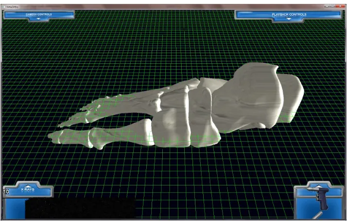
7.1 Mesh 1 - a foot model with a high polygon-count . . . 64
7.2 Mesh 2 - a sphere with a low polygon-count . . . 65
7.3 Cutting Model 1 . . . 66
7.4 Subdividing Model 1 . . . 66
7.6 Subdividing Model 2 . . . 66
7.7 Cutting Model 1 . . . 67
7.8 Subdividing Model 1 . . . 67
7.9 Cutting Model 2 . . . 67
7.10 Subdividing Model 2 . . . 67
7.11 Time spent removing triangles with and without the optimisation, for both meshes . . . 69
List of Tables
Glossary
CSG Constructive Solid Geometry; A system of representing geometry as a series of Boolean set operations performed on primitives
Index buffer A contiguous chunk of memory for storing indices which reference entries in a vertex buffer, allowing deduplication of vertices
Mesh A collection of connected polygons, commonly stored as triangles in index and vertex buffers
Metaballs A system of representing implicit geometry, often collections of ‘blobby’ spheres
Octree A spatial partitioning system that allows efficient searching through geometry
Orthopaedic The branch of medicine specialising in correcting problems relating to the skeletal system
Podiatric The branch of medicine concerning the feet and lower extremities
Serious game An activity that uses methods commonly employed for interactive entertainment to instruct or teach
Vertex buffer A contiguous chunk of memory for storing properties of a mesh’s vertices, each entry usually containing its position, normal, texture coordinates, colour, etc.
Volumetric A method of representing geometry by storing its volume as a collection of uniform elements in 3D space
Chapter 1
Introduction
The concept of training simulators has been around for many years (Bell and O’Keefe, 1987). Perhaps the most well-known type of simulator is the flight simulator, used as part of a training regime to train pilots and to provide entertainment. In the field of Serious Games, software applications are developed that repurpose entertainment-based computer game technologies for training, education and other serious purposes (Sørensen, 2005). Several serious games provide medical training, with some of the more advanced examples simulating surgery (e.g. France et al., 2005).
This research investigates methods for simulating orthopaedic foot surgery. This kind of surgery is carried out by both podiatric surgeons and orthopaedic surgeons, and is used to treat a variety of ailments affecting the bones of the lower extremities (O’Kane and Kilmartin, 2007). The goal of this research is to lay the foundation for developing a full-featured serious game simulating podiatric orthopaedic surgery, by overcoming one of the major technical obstacles. Such a simulator would be useful to consultant surgeons for demonstrating surgical procedures to trainee surgeons, and useful to trainees by allowing them to practice such procedures in a safe, controlled environment (Haluck et al., 2001).
In this introduction, we intend to briefly discuss how serious games technology can be used in a podiatric orthopaedic surgery simulator, and to provide an overview of the main problem this research intends to overcome.
1.1
Simulating Surgery
— for instance, in a bunionectomy (Mitchell et al., 1958) — and in others to temporarily sever part of a bone in order to reposition it, such as in the Scarf and Akin osteotomy (O’Kane and Kilmartin, 2002). Repositioning of bones can be used to lengthen or shorten a given bone if necessary, by making a diagonal cut all the way through a bone and sliding the two parts along the tangent of the cut.
Ideally, the user of the finished simulator would be able to repeatably experience a variety of podiatric orthopaedic operations, with both visual simulation and realistic tactile feedback provided by the simulator. Since we are primarily concerned with bone surgery, we do not intend to simulate the soft tissue surrounding bones, so the simulator will focus on operating on the skeleton of the simulated patient’s foot. Therefore, all the techniques of direct bone surgery used in the operation will be simulated, but supporting techniques such as anaesthetics, applying tourniquets, performing incisions into the skin to reveal the bone, suturing the wound, etc. will not be included and presumed to have been completed successfully.
1.2
Use of Serious Games
Although physical simulators can be used to train surgeons, this research aims to produce software and algorithms to be used in a computer-based training simulation. Since surgical operations take place in 3 dimensions in the real world, and the experience and motor skills we intend to convey cannot reasonably be transferred to a 2-dimensional representation, any surgical simulation software will necessarily entail a 3D rendered view of the operation scene. Such a scene will contain the subject of the operation (in our case, the skeleton of a simulated patient’s foot) and all tools relevant to the operation being performed. The simulated tools available in the application at this stage of research will primarily include a surgical bone-saw, but in the finished product may also included a drill, cutting guide and wire insertion tool.
Although some serious games are physical games (board- or card-games), and some are 2D games, there are a large selection of serious games that attempt to fully immerse the player in a realistic 3D-rendered environment. Such games primarily employ technologies originally developed by the (entertainment-focussed) games industry for simulating 3D game worlds, objects, characters, tools, weapons, in-world controls, out-of-world information displays, and many other relevant technologies and methodologies.
window. For example, one screen will allow the user to select an operation to attempt, which will lead to a second screen featuring a 3D environment replicating the chosen operation. In a finished serious game derived from our work, the user would also be given a score based on their performance while conducting the operation. The user’s speed, accuracy and appropriate use of surgical tools will be assessed to determine their score. This, combined with a system for managing multiple users, would provide metrics allowing them to measure their skill at performing given operations, and allow improvements in their performance to be measured over time. However, implementing specific, realistic scenarios with actual pedagogical benefit is beyond the scope of this work.
1.3
Mesh Cutting
In order to allow the user to perform orthopaedic operations in a simulation, it is first necessary to present virtual representations of the patient’s foot and the surgical implements to the user. There are several systems of representing 3D objects in a computer simulation, the most relevant of which are discussed in chapter 2. However, our system uses 3D polygon meshes rendered in a conventional manner, discussed in section 5.2. In order to perform surgical manipulation of the simulated patient’s foot when represented this way, it is necessary to be able to cut through polygon meshes in a manner simulating cutting through actual bone.
Typically, in 3D graphics, meshes are either rendered unmodified (for instance, with static scenery) or animated. Meshes can be animated in a variety of ways, which include simple geometric transforma-tions, skeletal animation, and facial animation. The most common manner in which these methods are employed is in replaying pre-recorded animations, although some animation systems generate anima-tions on-the-fly in response to the mesh’s environment and stimuli. Notable examples of such animation systems include various common rag-doll physics systems, and the Euphoria dynamic animation en-gine (McEachern, 2008). However, even with dynamically generated animations and interactions, the meshes in question are generally animated using a pre-determined ‘skin’ and a collection of jointed ‘bones’ — sets of vertices that are associated with a simulated skeleton. Such animation methods can be used to provide a full range of motion for the ‘bones’ attached to the mesh — often these correspond with accurately-simulated limbs and joints — but such methods can only move vertices around and not normally break or cut into the mesh.
the limited CPU, GPU, main memory, graphics memory, memory bus and disk I/O resources available within each frame. A suitable cutting algorithm must be able to operate using minimal amounts of these resources, as the remainder of the simulation’s functionality (such as rendering the 3D environment, drawing the user interface, responding to events, etc.) will also consume a considerable portion of the available resources.
1.4
Conclusion
Chapter 2
Literature Review
This chapter provides an overview of the current literature available on the topics of serious games, surgical cutting simulations and mesh cutting algorithms. The chapter discusses the nature of serious games, and describes some of the design elements, methodologies and technologies that are adopted from entertainment computer games. It also introduces the concept of mesh cutting and provides a brief look at the cutting algorithms currently described in the literature.
2.1
Introduction
The concept of serious games has been around for some time. Serious games aim to utilise technology and methodology normally employed in entertainment-based games, and convert them to serve educa-tional or other more practical purposes (Stapleton, 2004). Some serious games take the form of board and card games, but recently many computer- and video-games have been produced specifically for serious, non-entertainment purposes. For instance, the US government funds the creation, distribution and maintenance ofAmerica’s Army (Li, 2004). This is a game that attempts to accurately simulate actual military service — for recruitment and propaganda purposes — whilst maintaining the enter-tainment features underpinning games of its genre. Another example isBioHazard, a simulator used to train firefighters how to deal with emergency situations resulting from chemical and biological weapon attacks (Squire and Jenkins, 2003). The following section reviews literature available on the current state of serious games, and examines how they can be used for medical simulation.
2.2
Use of Serious Games Technology and Methodology
the game.” Very few, if any, video games can be completed by a player who has no prior knowledge of the game platform, genre and controls. Similarly, how to ‘beat’ the game must be learnt — the layout of game levels, the strategies required to beat certain enemies and the method to solve puzzles must all be discovered by the player as they play the game. Stapleton contrasts the learning that takes place within a computer game to that which takes place within a classroom. He notes that, in computer games, the player has full control over their learning, including the pace and content of their learning; whereas with conventional classroom-based learning, the lesson is conducted at a pace dictated by the instructor and as such is more focussed on the teacher. Stapleton believes this gives serious games greater teaching and learning potential than traditional methods.
Blackman (2005) explores several advantages that computer-based serious games offer over tradi-tional off-line educatradi-tional methods. She cites the example of learning to identify components in a piece of machinery, which would traditionally use a diagram of an ‘exploded’ view of the machinery to indicate the identity of components and how they fit together. This is contrasted with a theoretical interactive view of machinery components that allows the user to select components to view individ-ually, and display pertinent information accordingly. This avoids the overwhelmingly large amount of information that is necessary for the traditional diagram to be used with machinery containing a large number of components. Additionally, Blackman notes that entirely new learning methods are possible through serious games, such as allowing the user to view a 3D model of the working machinery. Of particular relevance to our research, she expands thus:
“Educational I3D [Interactive 3D] applications can be as complex and serious as visualiza-tions that teach medical students everything from bone, organ or tissue identification... to their first look at the steps involved in performing a complicated medical procedure. Almost any situation that requires previous knowledge, skill or decision-making could be set in an interactive 3D environment for considerably more effective results.”
2.3
Surgical Simulation
2.3.1
Soft-tissue Simulation
Choi et al. (2002) propose and develop a system of deforming soft tissue in real-time using a mass-spring elasticity model. Although soft-tissue simulation had previously been implemented by others, earlier methods were typically computationally intensive and not capable of running at the refresh rates required for a fully-interactive real-time simulation (Delingette, 1998). In order to solve this problem, the authors use a force-propagation algorithm to vastly reduce the number of calculations requires per simulation step whilst maintaining a good approximation of real-world tissue elasticity. In one example, the system displays a 3D model of the human stomach, to which a force is applied. The system is then used to iteratively calculate the relevant forces applied to or exerted by all the vertices near the force application point, causing the mesh to deform realistically.
2.3.2
Bone Simulation
Other research has been focussed on the simulation of bone surgery. Pflesser et al. (2000) presents a volume rendering system for visualizing bone dissections (such as mastoidectomies), which uses a sub-voxel rendering method to accurately simulate sections of bone being cut with a variety of tools. A further-developed version of this system is also described in the literature (Petersik et al., 2002), which incorporates haptic feedback to make the system more realistic. Similar systems are presented by Morris et al. (2004, 2006), again using volume rendering to provide haptic feedback. However, this system employs a hybrid data structure for the rendering, which produces a triangle mesh from the volumetric model data for conventional rendering. The vertex positions are inferred from the volumetric data, using pre-calculated normal and texture co-ordinate information. Cutting is only performed on the volume data, with the polygon mesh being regenerated from the resulting voxels. Indeed, as the cutting performed with this system simulates that of a burr — a type of surgical drillhead — a volume data structure is well suited to this task, as the volumetric nature of the geometry allows arbitrary-shaped volumes to be removed at will. This kind of volumetric system is also employed by Agus et al. (2002, 2003).
2.3.3
Evaluation
will typically be straight, and remove a narrow channel of bone in front of the saw blade. Therefore, although soft tissue cutting is somewhat relevant to our research, and uses many of the same concepts as we intend to use, the mass-spring elasticity algorithms for deforming soft tissue will not produce a suitable result when simulating bone.
Regarding volumetric approaches, we also do not believe these solutions to be optimal for the kind of cutting we intend to perform. This is partly because of the performance costs and complexity associated with volume rendering, but also because we believe that the cuts we intend to simulate will not be modelled very accurately or efficiently by a volumetric model. There are three reasons for why we believe this to be the case: first, only a very narrow sliver of bone matter will be removed when cutting through a model, so the vast amount of data in a volumetric model would be unused. Second, it will be necessary for part of the volume to be severed, moved and reattached at a different angle. The movement of a severed piece of bone could be simulated within the same volumetric model as the rest of the bone, in which case a large amount of data must be moved around per frame and likely cause a large performance loss. Alternatively, the severed bone could be split off into its own volumetric model, which would be more performant, but would entail running two separate volumetric models in very close proximity, with the possibility of them overlapping. Both of these alternatives lead to additional, undesirable complications. Third, when cutting through a volumetric model at any non-axis-aligned angle, a ‘stair-step’ of voxels will be left behind by the cut, resulting in a cut whose roughness will depend on the angle of inclination of the cut and the granularity of the voxels. Thus, in order to smoothly cut through a volumetric model, the model must be extremely fine-grained in order to alleviate this issue. Using a volumetric model of uniform density with the required granularity would be inefficient, as cutting operations will only involve a small part of the model, and therefore only relevant areas of the model require this granularity. However, to limit the overhead of increased density in the model, a low-density model could be used initially, and the level of detail in areas affected by cutting be increased as necessary. Voxels near to the local area affected by cutting would be subdivided to increase the density in the relevant area.
2.4
Mesh Cutting
2.4.1
Mesh Sculpting
One of the simplest methods of altering a 3D polygon mesh is to sculpt its surfaces. Generally speaking, when a mesh is sculpted, some of its constituent vertices are moved based on their proximity to a user-controlled tool in a manner governed by one of several sculpting algorithms. Of particular note, one of the earliest computer sculpting systems allowed the user to control the sculpting operation using a polyhedral tool (Parent, 1977), an idea considered advanced for its time. More impressively, the tool could be modelled using the sculpting software itself to allow the user a finer degree of control. The system we propose will support multiple polygon-mesh-based tools that the user can control, although ours will be predefined meshes based on real-world equivalent surgical tools. (Notably, this system also allowed the user to cut out a section of the sculpted object, using the volume of the tool as a guide. However, this was achieved using constructive solid geometry techniques — which are discussed later — as opposed to sculpting techniques.)
In most early sculpting systems, standard computer controls (such as a keyboard and mouse) were used to control the sculpting tool. However, LeBlanc et al. (1991) proposed a system using the Spaceball 6D human interface device, which allows the user 6 degrees of freedom in their input. This device is used with one hand, and a computer mouse in the other hand, to more accurately perform sculpting. We intend to use a similar, but more modern, device (the Sensable Phantom) to allow the user to control our system.
In terms of the algorithms used to perform sculpting, Parent used ‘decay functions’ to determine the effect of the user’s input on individual vertices, based on proximity to the position of the user’s tool. These decay function were refined by later researchers, who also included the use of techniques such as polygon subdivision. This technique was applied to the whole mesh by Allan et al. (1989), and later refined into an adaptive subdivision by Bill (1994), in order to afford the user a finer degree of control over the manipulated surface.
2.4.2
Metaballs
surfaces created by metaballs are the result of blended continuous algebraic functions (as opposed to the discrete geometric segments in polygon mesh geometry), they provide a smooth transition between their different functions and as a result produce very smooth, soft-looking structures.
Figure 2.1: Three metaballs
A simple way of using metaballs is to define a set of control points with corresponding radii of influence. The described geometry would then consist of the surface(s) containing all points whose total influence from all control points equals a given threshold value.
For example, with control pointscn∈ <3 and control radiirn, the influenceI applied to any point
p∈ <3 from each metaball could be calculated individually as:
Ii= ri
||ci−p||2
In this case, the surface to render contains all points in Euclidean 3-space where the sum of the influence from all metaballs equals the threshold, i.e.
n
X
i=1
Ii=T
This can be expressed in the formF(x, y, z) = 0, where
x y z
≡p, as follows:
F(x, y, z) =−T+
n
X
i=1
Ii
=−T+
n
X
i=1
ri
||ci−p||2
=−T+
n
X
i=1
ri
p
(cix−x)2+ (ciy−y)2+ (ciz−z)2
of points within an area below the required threshold. One or more suitably positioned metaballs can be used in this manner to create a soft cut through a metaball surface.
Figure 2.2: Three positive metaballs with a negative metaball
Once a function has been determined that defines the metaballs’ implicit surface, there are a number of methods of producing a rendering of the geometry described. The surfaces of the metaballs can be ray-traced by solving their equations algebraically — as in Blinn (1982) and with any of several numerical methods described by Hart (1993) — or a polygon mesh can be generated as an approximation of the metaball’s implied surfaces. A polygonal approximation can be generated by progressively subdividing the space enclosed by the implicit surface, for instance by using an octree (Bloomenthal, 1988), and creating polygons based on the implicit surface’s intersections with the subdivision structure.
The advantage with having a polygonal approximation of a metaball structure is that modern graphics hardware is specifically designed to quickly and efficiently render polygon meshes, whereas ray-tracing does not currently enjoy such support. However, whilst the output of a metaball system can be a polygon mesh, the input can not. In other words, traditional polyhedral geometries cannot be automatically converted to metaball-based structures. An approximation could be made using numerous tiny metaballs, in a manner analogous to the voxels used in volumetric rendering — however, using this approach would be very inefficient, with an excessively large number of metaballs being required. Using a simple volumetric representation of the polyhedra would likely provide a more efficient solution. As such, in order to use metaballs within an orthopaedic simulation, a model of the patient’s foot must first be constructed entirely from metaballs. This would require a modelling expert to be available for the laborious task of remodelling any and all polyhedral meshes desired to be used with the system.
2.4.3
Constructive Solid Geometry
are applied to the volume enclosed by the combined geometries. The surface produced as a result of these operations contains the volume previously occupied by either object, only one object, or both objects, respectively. Entire geometries can be represented by a hierarchy of CSG operations performed on implicit primitives and the results of previous operations, forming a binary tree of set operations (Requicha, 1980). The terminal nodes in such a tree represent implicit primitives, and the nonterminal nodes represent a single binary set operation performed on the two child nodes. Geometry represented this way is often used in computer-aided design for manufacturing purposes, as it allows highly accurate smooth surfaces and intersections to be represented, and may also be used with other operations, such as translational and rotational sweeps.
Figure 2.3: Two shapes before a CSG operation
Figure 2.4: The result of a CSG operation
[image:22.612.252.342.437.530.2]level of detail and accuracy in the rendering, but its approximate nature is considered an acceptable tradeoff since it allows the geometry to be rendered at refresh rates suitable for interactive viewing and manipulation of the CSG tree. This tradeoff would be especially important for an application such as surgical simulation, where viewing and modifying the geometry would be required to take place in real-time.
2.4.4
Polyhedral Boolean Set Operations
Another disadvantage that CSG trees share with metaballs is that polygon-mesh geometry cannot be easily converted to this format. If a tetrahedralization of the polygon mesh could be generated, then the resulting list of tetrahedrons could be rendered as a CSG tree. However, doing so would be highly inefficient and would likely be unsuitable for real-time rendering. Therefore, reference data of medically-accurate foot models represented as polygon meshes cannot be used as a CSG tree.
However, operations topologically equivalent to the Boolean set operations used in CSG trees may be applied directly to polygon mesh geometry (Aftosmis et al., 1998). When applied to polyhedra, the boundary representation of each object’s surface is segmented based on its intersection with the other object. The segments of each object are then combined into a new polygon mesh or discarded, based on their relationship to the other object. Of particular relevance is the Boolean subtraction (difference) operation, which forms a new object containing the volume enclosed by one object but unenclosed by the other. The object to be subtracted from discards all portions of its surfaces which lie within the subtracting object and retains the remainder; whereas the subtracting object discards all portions of its surfaces that lie outside the subtractee object and retains those which lie inside it. This Boolean subtraction operation is commonly available in 3D-modelling software, and has also been used in industrial simulation software — for example, in simulated log sawing (Occena and Tanchoco, 1988).
2.5
Conclusions
Serious games provide a safe, cost-effective way of providing information and training in many disci-plines. When designed correctly, they engage their users effectively and provide an incentive for the user to learn. Serious games permit the automation of many tasks, such as evaluating users’ performance, and therefore allow more efficient use of instructors’ time. Users of serious games can learn at their own pace, with education customized to their level. Serious games complement, but cannot completely replace, real-world training.
Several studies have used serious games technology for medical training, some for basic planning and organisation simulations, but others have created virtual surgery training applications. Some have even simulated bone surgery, using a volume-rendering based approach. However, the type of bone surgery commonly simulated uses a surgical burr to ‘drill’ away bone as opposed to cutting it with a surgical electric saw. Our research intends to simulate a different kind of cutting, which will largely involve making narrow cuts through (and potentially repositioning) simulated bone. The anatomy being simulated in our application will be the skeleton of a foot. For our purposes, we believe representing the foot using polygon meshes will provide benefits over using volumetric data and as such require a suitable algorithm to allow realistic cutting through polygon meshes.
Chapter 3
Research Methodology
This chapter discusses how we intend to reach the stated goals of our research, and describes the methodology we intend to follow.
3.1
Introduction
The main focus of this research is to design, develop and test a software simulation of bone surgery. It must be capable of allowing users to cut through a virtual represention of the bones of a simulated patient’s foot, in a surgical manner. In the literature reviewed in the previous chapter, four methods of mesh cutting were described. The most suitable method, performing a Boolean subtraction operation on a polyhedral mesh, will be investigated further. It is expected that a conventional implementation of this algorithm will be unsuitable for real-time manipulation of meshes, as high frequency iterations of Boolean subtraction in the same local area of a mesh would recursively create more triangles. There-fore, we will investigate how to achieve a similar end-result to repeated Boolean subtractions along a path, whilst avoiding such high levels of computational complexity and the potential of exponentially increasing the number of triangles in the target mesh.
3.2
Hardware
haptic force feedback enhances the user’s perception of the virtual environment in which they operate. These combined technologies allow an application to take real 3D input and produce apparently real 3D output, which can potentially provide a much greater sense of immersion in the virtual world than would be provided by many conventional simulation applications.
3.3
Preparation
As a framework to facilitate the implementation and testing of various 3D algorithms, a simple ap-plication will be set up to provide basic user interface and rendering capabilities. This apap-plication will allow the user to select one of several scenarios, each of which may have a different 3D model and predefined parameters associated with it. The user will also be able to move, rotate and zoom their view of the virtual world and provide 3D input through the use of the Phantom haptic controller linked to a virtual saw. This application is a supporting part of the research, and not its current focus. However, the application may provide a suitable basis for future work developing a complete virtual surgery simulation.
We are not using a pre-built game or rendering engine, as doing so would add unnecessary extra development complexity in return for a large corpus of unused functionality. We are developing for Microsoft Windows-based systems, and using the DirectX D3D9 rendering API. Since the cutting methods being investigated will primarily be executed on the CPU, and the graphics pipeline will only be used for simple rendering of the results, the specific graphics API used should have little bearing on the project. As the graphics API will merely be used to render a handful of meshes and present a 2D user interface, we chose a platform with which we are familiar enough to develop quickly and efficiently. Algorithm implementations will be done in C++, in an object-oriented manner. The classes required for investigating mesh cutting will be implemented in a static library, which the supporting application will link to. In order to manipulate mesh geometry more easily, an object-oriented representation of the geometry will be stored in addition to the standard hardware-optimised buffers (see section 5.4).
3.4
Development
suitable cutting method would possess. We will search for methods that will either optimise the Boolean subtraction algorithm, or provide an alternative method of cutting. When a suitable algorithm has been finalised, this will be implemented with the framework application discussed earlier and developed to a usable state. Assuming a viable algorithm can be implemented, it will be assessed for speed, cutting accuracy and visual realism. This will include gathering metrics on the algorithm’s performance on multiple test machines with multiple test meshes.
3.5
Testing Vertex and Index Buffer Modifications
One challenge to modifying meshes in real-time is updating the version of the geometry given to the graphics pipeline. Updating the index and vertex buffers containing the hardware-preferred represen-tation of the geometry of the mesh can introduce a non-trivial delay. Performing large numbers of updates to the respective buffers per refresh cycle can create a performance bottleneck severe enough to slow down the application. In order to counteract this bottleneck, we discuss optimizations to the use of the respective buffers in section 5.3.1. To gauge the impact of these optimizations, we will run a series of benchmarks with an automated process set up to repeatably modify a mesh, and compare the performance of the process both with and without these optimizations.
The operations being optimised are appending and removing vertices; and appending and removing indices. Our benchmarks will record the time required to perform each of these operations on large numbers of vertices, both with and without the optimisations discussed in section 5.3.1. We will perform the benchmarks on several meshes, recording the time taken to update the buffers for each operation. For the unoptimised, na¨ıve version of operation, a new buffer will be allocated and data will be copied in from the old buffer. This will be compared and contrasted with the optimised version presented in section 5.3.1.
The optimization for appending vertices or indices to an existing buffer requires buffers to have extra space preallocated, to allow for future expansion. We will test the performance difference obtained when using different allocation schemes of adding between 1% and 20% extra, in increments of 1%. As a control group, we will use the unoptimised method of not preallocating any extra space. We will test each method by repeatedly adding triangles over several rendered frames and recording both the total time taken, and the time taken to add the additional triangles. In order to simulate the adding of extra triangles, we will use two processes — first, we will use a cutting algorithm and simulate cuts through different parts of each mesh. Second, we will simply progressively subdivide the mesh over a long series of frames, by subdividing 0.1% of the mesh’s original triangles each frame.
we will set up a test environment similar to that mentioned above, except that this time a proportion of the mesh’s triangles will be removed per frame.
3.6
Testing Cutting Algorithms
The key metric for determining the cutting algorithm’s performance is the refresh rate at which it operates. The algorithm’s refresh rate will directly affect the overall frame-rate of the application which employs it. In order for an application to be suitable for interactive use, it must maintain a frame-rate averaging above 20 frames per second. Spikes and troughs in the frame-rate of the application are to be expected, as the computational intensity of the algorithm will vary with the precise angle of cut being made, the number of polygons being cut and other factors such as the current viewing angle for the mesh. Since the application is running in a shared environment with other processes on the machine, factors not directly controlled by the algorithm may significantly contribute to the frame-rate.
Chapter 4
Mesh Cutting Operations
Performing interactive cutting through a mesh requires a cutting algorithm which can operate at real-time refresh rates. It must do so within the constraints of the limited resources available to an appli-cation each frame after normal processing and rendering is taken into account. The purpose of this chapter is to briefly evaluate the suitability of several conventional methods of cutting meshes to our system, and to develop an algorithm suitable for real-time cutting.
4.1
Introduction
There are several methods of removing a given volume from geometry representing a solid object. Some common geometric operations that can remove part of the volume of a mesh include: mesh sculpting, use of negative metaballs, constructive solid geometry trees, and polyhedral Boolean subtraction. Each of these methods has a number of advantages and disadvantages, and a varying degree of complexity to implement. Although geometry represented by some of these methods can be ray-traced for rendering, all methods either operate on polygon meshes or can generate approximate meshes. Polygon meshes are the preferred representation of geometry by conventional graphics hardware for real-time rendering. When meshes are modified or generated, care must be taken to ensure the user does not see inside the mesh, otherwise its hollow nature is revealed and the illusion of solidity is lost. The simplest way to maintain this illusion is to ensure the mesh is a closed surface — this requires any holes cut into a mesh to be sealed with additional polygons. These extra polygons would generally demarcate the boundary of the volume removed, which must not intersect the outer faces of the mesh and thus protrude through the opposite site of the mesh in an unrealistic manner.
et al., 2009). The result of this effect is that the overlapping area inhabited by two or more coplanar (or nearly co-planar) polygons will be rendered with fragments arbitrarily chosen from the competing polygons, resulting in semi-random noise. The z-fighting is due to the overlapping fragments having the same depth values, and since they are rendered in parallel, a race condition occurs between the competing fragments. It can be avoided simply by ensuring coplanar polygons do not overlap.
4.2
Overview of Conventional Methods
4.2.1
Sculpting
Sculpting, the simplest of the above operations, does not primarily add or remove any polygons, but instead moves existing vertices in a manner defined by the given sculpting algorithm (see section 2.4.1). Affected polygons are usually subdivided when being sculpted. This increases the resolution of the sculpting operation by increasing the density of vertices in the affected area, and as a result produces a much smoother deformation of the mesh.
The actual deformation caused by a sculpt operation is determined by the sculpting algorithm used and the shape of the ‘tool’ used to sculpt with. For instance, a simple algorithm is to repel all vertices within a given radius of the tool’s origin, pushing them along the vector between the tool’s origin and the vertex position. The result of this example operation is a spherical indentation forming around the tool. To increase the smoothness of the scuplt operation, any polygons that are sufficiently stretched will be subdivided to increase the resolution of the deformation. Stretching of polygons can be determined by comparing their current surface area to their original surface area, and an increase exceeding a given percentage of area will cause the polygon to be subdivided.
op-eration, and relatively straightforward to implement in its standard forms, in order to be useful the process would have to be substantially modified with complex constructive solid geometry techniques. Therefore, it seems unwise to start with sculpting as the basis of the cutting algorithm.
4.2.2
Metaballs
Metaballs are a system of storing and representing an object’s volume data without storing its exact surface geometry (Blinn, 1982). Typically, each metaball has an origin and radius of influence. Based on this, a level of influence is calculated for any given point in 3D space based on the inverse square of its distance from the metaball’s origin, and the metaball’s radius. Whether a given point is part of the volume represented by the metaballs is determined by whether the sum of all influences from all metaballs in the scene is greater than a given threshold value. When rendered, a single metaball will visualise as a perfect sphere, as will any metaballs of sufficient distance from one-another (relative to their radii). However, when two or more metaballs come into close proximity to each other, the sum of the level of influence for some points between the metaballs that would otherwise not be rendered will become greater than the threshold value, leading to the surface each metaball warping towards the other. Visually, the effect of two metaballs approaching each other resembles water droplets coalescing. Metaballs can exert negative influence as well as positive influence. The effect of a positive meta-ball (visualising as a perfect sphere) approaching a negative metameta-ball is that the sphere will become ‘indented’ in the area affected by the negative metaball. The negative metaball appears to exert a repelling force on the surface of the sphere. A line of small, negative metaballs passing through a large, positive metaball would have the appearance of a hole being drilled through a sphere. More compli-cated shapes can be cut out of the volume created by positive metaballs by using larger number of small negative metaballs. The shapes created by metaballs always have rounded edges, due to the spherical nature of all the components used to create them. In order to remove a more precise volume from a shape, constructive solid geometry operations can be used — specifically the Boolean subtraction (or difference) operation.
4.2.3
CSG trees
Another system of storing and displaying geometry through means of implicit surfaces is to use con-structive solid geometry (CSG) trees. A CSG tree is constructed from terminal nodes (which represent implicit solids) and non-terminal nodes (which represent operations carried out on the child nodes of the given non-terminal node). The three operations used in CSG trees are set operations — union, difference and intersection. The results of performing these operations can be used as operands in further operations. In this way, it is possible to build up a tree of operations, adding extra primitives where necessary (Requicha, 1980).
CSG trees can be rendered using ray-tracing, where each pixel casts a hypothetical ray into the scene and determines if and at what distance the ray will intersect the geometry resulting from the tree of CSG operations. They may also be polygonized for more efficient rendering by conventional graphics hardware.
The major drawback to using CSG trees to simulate bone cutting is similar to that of using meta-balls — the entire geometry of the CSG tree must be represented using CSG operations and implicit primitives. There is no easy way to automatically convert an arbitrary polygon mesh to a CSG tree representation, so this again would require a skilled modeller to laboriously create a CSG approxima-tion of any reference foot meshes. However, each of the Boolean set operaapproxima-tions used in CSG modelling can be applied to polyhedral meshes using geometric methods instead of implicit surface methods. We believe these geometric Boolean set operations may be useful for simulating cutting, especially Boolean difference (or subtraction).
4.2.4
Boolean subtraction
split.
Polygons which are to be split are intersected with the opposing mesh, and are tested against all intersecting polygons. For each polygon to split, a list of line segments lying on the surface of the triangle can be generated which denote the curve(s) of intersection between the splitting polygon and the intersecting polygons from the opposing mesh. When intersecting with a closed mesh, all polygons will be adjacent to other polygons on all sides, so the line segments generated will always form a closed path when combined with any segments of the splitting triangle’s edges that lie within the other mesh. From these closed paths, a new set of polygons can be generated that cover the area of the splitting triangle either enclosed or excluded by the paths. These polygons are then added to the list of retained polygons for the final output of the operation.
The resultant mesh is created from the polygons retained from A and B and those generated by splitting partially retained polygons.
4.2.5
Conclusion
The mesh sculpting method cannot feasibly be used to simulate bone surgery, due to the lack of realism that would be apparent. Modifications to the sculpting algorithm could be made to compensate for this, but the end result would essentially be Boolean subtraction. Using metaballs would have some of the same drawbacks as sculpting, with both being more suited to defining rounded edges. However, the major caveat of using metaballs is the inability to easily convert a mesh with a large number of polygons to a metaball-based structure. The Boolean subtraction method should provide accurate cutting simulation. However, it is not designed to be employed repeatedly on a mesh at high refresh-rates. The following section describes some of the limitations that cause this.
4.3
Disadvantages of Boolean Subtraction
4.3.1
Geometry-in-polyhedron Testing
In order to compute the result of a Boolean subtraction operation, it is necessary to know which polygons in each lie wholly or partially inside or outside the other mesh. Therefore, it is generally necessary to test all the polygons in each mesh to determine which lie entirely outside of the other mesh, which lie entirely inside of the other mesh, and those that lie partially inside and partially outside the other. To test for which of these conditions applies to each polygon, it is usually only necessary to determine whether each of its vertices lie inside or outside the other mesh. This test can be performed in a number of ways — the easiest being the ray-cast method.
or not using ray-casting, rays must be emitted from the point, and the number of triangles the ray intersects counted. A simple test with a closed mesh can be performed using only two rays, both emitted in opposite directions — if both rays pass through an odd number of surfaces, then the point is enclosed on both sides. Where the number of surfaces is even or zero, the point is outside the mesh. All polygons in each mesh must be tested to determine whether they intersect the other mesh, which entails testing all vertices in each mesh. Assuming a suitable spatial subdivision technique is used to optimise the ray test, each test will be of O(1) complexity in the average case, and O(n) in the worst case (Szirmay-Kalos and M´arton, 1998). Since all vertices must be tested per Boolean operation, this results in an overall complexity of O(n) (average case) or O(n2) (worst case) for the intersection tests.
The remainder of the algorithm will require classifying all polygons based on their intersection or non-intersection of the opposing mesh (O(n)), adding each new vertex or index (reallocating buffers each time would be O(n2); with optimised buffers this is closer to O(n)) and removing deleted vertices
and indices (O(n)).
[image:34.612.196.416.358.555.2]4.3.2
Segmentation of Triangles
Figure 4.1: Triangle split into three.
along it. In the best case of segmenting a triangle like this, 3 triangles must be added for each triangle removed. However, for triangles containing multiple segments of a curve of intersection, a minimum of five additional triangles are added for each triangle removed. Triangles containing two opposing edges of a curve of intersection must be separated in a more complex manner; triangles containing multiple curves even more so.
These operations do not present a significant time penalty when the operation is to be carried out once, even for large meshes. However, for our purposes, the cutting operation must be carried out and visualized once per frame. This requires the Boolean subtraction to take a maximum of 1/25 seconds, or 40ms. Under the circumstances the operation will be used for — few polygons will lie inside the cutting volume, many more will lie on the boundary and require splitting. Unless both polyhedra have a similar density of vertices around the intersecting area, the segmentation will generate a large number of small triangle fragments — there will be a constant net increase in polygons. As more polygons are generated, more polygons will be split per frame, potentially resulting in an exponential growth in the number of polygons in the target mesh. This leads to a constant slowdown of the cutting operation.
The problem of exponentially-increasing polygon count can be mitigated somewhat by mesh simpli-fication. There are several techniques that reduce the number of polygons in a mesh whilst retaining an approximation of its original shape (for instance, see Turk, 1992). However, simplification algorithms typically operate on an entire mesh and this adds to the processing time required (Kalvin and Taylor, 2002). Assuming a suitable algorithm could be implemented that efficiently simplified only the geom-etry modified by the Boolean operation each frame, it must keep the number of polygons in the mesh largely constant over several iterations of the cutting algorithms.
4.4
Simplification of Serial Boolean Operations
4.4.1
Cutting Cross-sections
Consider the case where one or a series of Boolean subtractions (using a convex polyhedral cutting volume) cut through the complete cross-section of a convex triangle mesh. This will sever one part of the mesh from another, to form two new meshes. Once the cut is complete, all the triangles in the original mesh which are outside of the cutting volume will have been separated into two groups — one group on each side of the cutting volume. Triangles intersecting the surface of the cutting volume will have been split accordingly, and the resulting triangle fragments will have been placed into the appropriate group given their position. The newly-hewn sides of the two new meshes (which previously intersected the cutting volume) are defined by two surfaces. These surfaces are bounded by the curves of intersection formed between the sides of the cutting volume and the mesh.
and separate triangles into groups based on which side of the surfaces they lie on. The geometry that lies between the two cutting surfaces would be discarded, and the rest would be added to whichever of the two newly-created meshes is appropriate, based on its position relative to the surfaces. The geometry of each cutting surface would be appended to the new mesh adjacent to it.
4.4.2
Biplanar Subtraction
When cutting through bone (and for that matter, most hard surfaces over short distances), the path of the saw will typically follow a plane with a normal vector matching that of the saw blade. For our purposes in simulating bone surgery we shall assume that, for each cut made, the blade movement becomes limited to the plane defined by its position and normal when it first touches the bone. This implies that the saw blade cannot move along its normal vector due to matter either side of the blade, and the only axis it may rotate around is defined by its normal vector. Within these constraints, the series of Boolean subtraction operations described previously will remove a volume bounded by two surfaces lying on planes parallel to the cutting plane, separated by the width of the simulated blade.
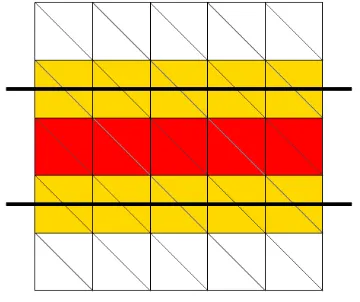
[image:36.612.107.287.341.492.2]Figure 4.2: Before biplanar subtraction. Red trian-gles are removed; yellow triantrian-gles are sliced.
Figure 4.3: After biplanar subtraction
Using this assumption — that the removed volume will be bounded by two planes lying parallel to the cutting plane — the process of separating the convex mesh geometry to produce the end-result of a complete cut can be greatly simplified. The mesh can be divided into two new meshes, with the geometry between the two planes being removed and the rest being divided into one of the new meshes, based on its position relative to the cutting planes.
vector. If all of a triangle’s vertices lie on the same side of a plane, that plane does not intersect with the triangle. However, if one of the triangle’s vertices lies on a different side of a plane to the other two, the triangle must be divided along that plane to form three triangles, two of which will lie on one side of the plane, whereas the third triangle will lie on the other side. With the biplanar slicing method described above, this test is repeated for both planes. With large triangles that intersect both planes, there may be up to seven new triangles formed.
In order to categorise triangles using the biplanar slice method, a vector which is normal to both planes is used to arbitrarily define whether vertices lie ‘above’ or ‘below’ each plane. As the planes lie a distance apart, one plane is above the other as defined by this normal vector. After triangles have been sliced by both planes, those that lie between the two planes are discarded. Of the remaining triangles, those that lie above the topmost plane are collected into one mesh, whereas those that lie below the bottom plane are collected into the other. Finally, the vertices that lie on each cutting plane are used to create a ‘cap’ that seals the hole made by slicing the mesh into two. For slices with a convex cross-section, this can simply be done by creating a triangle ‘fan’ linking all the affected vertices.
4.4.3
Single Plane Slicing
The caveat with using the biplanar slice method is, of course, that as soon as it is applied, it appears that the user has sliced through the entire mesh. In order to overcome this, there are two possible approaches. After the biplanar slice is applied, the new geometry could be extruded to meet in the middle (along the plane defined by the constrained cutting motion of the saw), and as the blade passes near to the vertices involved, they can be returned to their original (separated) locations to create the illusion of slowly separating the mesh. However, for any triangles not exactly perpendicular to the cutting plane, this will cause a visual modification to the mesh at the instant that the biplanar method is applied, which is undesirable.
An alternative method is to perform the slice using only one plane (see figures 4.4, 4.5). All the triangles in the mesh lying on the slice plane will have been split along the plane, and no geometry will have been removed. (Unsliced triangles lying on the cutting plane will be removed, but the triangle fragments formed by slicing each of these along the plane will fill the exact same area that these previously filled, hence no geometry is lost). This planar partitioning process is used in binary space partitioning (BSP trees), where it is commonly used to divide a 3D scene graph into segments (Fuchs et al., 1980). A scene divided into a BSP tree can be used for more efficient rendering and collision detection, and BSP trees can be merged to perform CSG operations on the polyhedra they represent. In BSP trees, segements created by slicing do not have geometry added to create a visible partition -however, this is required for our purposes.
one for each mesh, effectively creating two barriers across the partition sliced. At the instant that a uniplanar slice is performed, there will be no visible difference in the mesh, despite it being separated into two discrete entities. However, as the blade of the saw passes near to each pair of the coexisting vertices in the sliced cross-section, they can be moved apart to create a gap in the mesh. This is consistent with the mesh being separated only as the blade of the saw passes through the geometry.
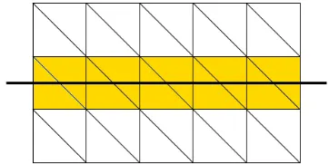
[image:38.612.105.286.173.264.2]Figure 4.4: Before single plane slice. Yellow trian-gles are sliced.
Figure 4.5: After single plane slice.
At any point whilst performing a series of Boolean subtractions on a mesh based on the position of the saw blade, all volume occupied by the blade throughout the previous series of iterations of the Boolean subtraction algorithm will have been removed from the initial mesh. Performing a uniplanar slice and separating the vertices as described above does not guarantee that this holds true, as the exact geometry of the blade is not removed per frame. However, since the geometry of the rendered saw blade obscures the cut whilst it is being made in the mesh, this inadequacy should not be noticable to the user.
4.4.4
Benefits of Single Plane Slicing
In terms of performance, this method requires an initial overhead of processing time (to compute the planar slice), but in subsequent frames the separation uses a minimal amount of processing time. This should allow a smooth frame-rate throughout the user’s cutting operation, enabling real-time cutting to be approximated.
Unlike Boolean subtraction, planar slicing does not require the geometry-in-polyhedron test to determine whether the cutting mesh (in this case, the cutting plane) lies within the target mesh. All the polygons in the target mesh must instead be tested to determine which side of the plane their vertices lie on. Although this is an operation of O(n) complexity, it need only be performed once (at the start of a cutting operation) instead of per frame as with Boolean subtraction.
triangles added is limited to 3nfor the worst-case of all triangles in the mesh lying on the cutting plane. However, in practice, the percentage of polygons in the mesh that intersect a given plane diminishes as the total number of polygons increase. From testing, we see a maximum of around 25% of polygons intersecting the cutting plane for meshes with low numbers of polygons, and around 1% for meshes with higher totals of polygons.
4.4.5
Drawbacks of Single Plane Slicing
With single plane slicing, the accuracy of the cut during intermediate frames is not as accurate as that possible when using Boolean subtraction. When a triangle fan is used to cap the two cross-sections, moving the vertices apart individually has the visual appearance of ‘folding’ the caps apart. However, the inaccuracy is typically only visible between the two cross-sections of the slice, which is difficult to see from a viewpoint outside of the mesh, and the geometry of the saw will tend to obscure these details in any event. Once the cut is complete, these inaccuracies are no longer visible. A more likely cause of visual inaccuracies is if when vertices are moved a given distance from the plane, they share edges with other vertices whose distance to the plane is less than the movement distance. This will cause edges that previously pointed towards the plane to now point away from it (or vice-versa), which in the best case will introduce new concavities into the mesh, and in the worst case will cause the extrusion away from the plane to crease back over other geometry, creating a visible fold around the edges of the slice. One way of mitigating this is to move all vertices within the movement distance from the cutting plane, instead of just the new vertices created along it. This will collapse all nearby vertices and edges onto a plane at the given distance from the cutting plane, eliminating any overlap.
4.5
Implementation of Single Plane Slicing
4.5.1
Dividing Along A Plane
Although the planar slice operation uses similar triangle intersection and splitting routines, it is some-what simpler to implement than that of the Boolean subtraction operation. In its simplest form, a mesh is divided along a single infinite plane. The constituent polygons of the mesh are divided into two groups — whether they are ‘above’ or ‘below’ the plane relative to its normal. Those lying entirely above or below the plane are simply placed into the relevant group; those lying on the plane are split along it. This usually results in three additional polygons being generated per polygon sliced — two on one side of the plane, and one on the other side.
[image:40.612.327.508.356.518.2]Whether a triangle intersects the cutting plane can be determined by comparing the signed distances of its vertices from the plane with one-another. If the distances of all three vertices are of the same sign, then the triangle does not intersect the plane and the triangle is placed whole into either group based on the sign. On the other hand, if one of the triangle’s vertices’ distance has a different sign to the other two, then the triangle does intersect the plane and must be sliced.
[image:40.612.107.290.365.513.2]Figure 4.6: Before splitting a triangle along a plane (line of intersection with plane marked as thick line).
Figure 4.7: After triangle is split.
When slicing a triangle that intersects the cutting plane, the triangle will split into three (see figure 4.7). The solitary vertex on one side of the plane is labelledA; the other twoBandC. The points of intersection betweenABandACare labelledPandQrespectively. In order to be able to manipulate geometry on both sides of the split independently, the verticesPandQ must be duplicated to create
P1,P2,Q1andQ2.
base of the quadrilateral. The other two edges are split at their point of intersection with the plane to form four smaller edges —AP1 andBP2 derived fromAB, andAQ1 andCQ2 derived fromAC.
4.5.2
Splitting Triangles
Calculating the point of intersection between an edge and a plane gives a distance along the edge, which can be normalized by dividing it by the total length of the edge. For edgepq where p,q ∈ <3, the
distance from vertexpto the point of intersection with a plane in the form
Ax+By+Cz+D= 0 is calculated with the formula:
d=A(qx−px) +√B(qy−py) +C(qz−pz) +D
A2+B2+C2
The normalized distance can then be obtained thus:
dnorm= d
||q−p||
This normalized distance can be used to produce a new vertex that lies on the plane. All the properties of the vertices at the opposing ends of the edge are linearly interpolated to produce the new blended vertex. As well as their positions, these properties will include all fields in the vertex format, including their normal vectors, colours, texture coordinates, tangents, binormals, etc.
Since the edge is to be divided into non-adjacent separated polygons, a copy of the interpolated vertex must be created. One of the vertices is associated with the edges and triangles on one side of the plane and the other vertex is associated with the edges and triangles on the opposite side of the plane.
When both intersecting edges have obtained a pair of interpolated vertices, three new triangles can be formed. On the side of the plane containing only one of the triangle’s vertices, a single new triangle is formed with the lone vertex and the two new vertices. On the opposite side of the plane, two triangles are necessary to form the base of the severed triangle — one takes the two pre-existing vertices along with a new vertex, whereas the other takes both new vertices and the pre-existing vertex adjacent to the new vertex that was not previously selected.
4.5.3
Capping
After the mesh has been split along the plane, the new edges created by splitting polygons should describe one or more closed paths on the surface of the plane. The area enclosed by these paths is then efficiently filled with non-overlapping co-planar polygons to form a cap. Such caps are necessary to maintain the illusion of solidity of the object, and are formed in pairs. A minimum number of polygons should be used to create the cap, as a large increase to the polygon count is undesirable.
[image:42.612.103.515.317.510.2]For cuts with convex cross-sections, a simple method of capping the sides of the cut is to create a triangle fan. A new vertex is added at the midpoint of the cross-section, which allows the original vertices to be sorted according to their bearing from the midpoint vertex. The vertex is created from a blend of the properties of all vertices in the cross-section, as described above. Once the vertices have been sorted, each vertex contributes a triangle to the cap. Each vertex’s triangle is comprised of the current vertex, the vertex following it in the list, and the midpoint. In order to ensure the fan seals the cap all the way round, the last vertex wraps around to use the first vertex as its following vertex.
Figure 4.8: Cross-section vertices before capping. Figure 4.9: After capping.
4.5.4
Localised Slicing
The disadvantage of performing the planar slice operation on all polygons comprising a mesh is that it will make a cut all the way through a mesh, separating any polygons that lie on the cutting plane. With convex meshes this will be desirable, but for our purposes of simulating surgery with concave geometry, it is necessary to cut through only the parts of the mesh which would be affected by the surgical tool. For example, when cutting into the side of a toe bone, the plane on which the cut is performed will almost always intersect the other toes, so an unbounded slice along this plane would cut matter not relevant to the operation. A localised version of the planar slice must therefore be used, by limiting the triangles on which the operation is performed.
Once a physical blade begins a cut on bone in real life, it naturally follows approximately the same plane due to pressure from matter either side of the blade. Therefore, when simulating this cut, all the relevant polygons will intersect with the plane whose normal vector matches that of the blade as it first begins the cutting operation. Additionally, once the blade cuts entirely through a section of matter, the cut is finished and any further cutting will be considered a separate operation. Therefore, the only relevant triangles are those whose lines of intersection with the cutting plane form a contiguous cross-section, starting with the triangle first intersected by the blade as it begins the cut.
Figure 4.10: Initial traversal. The green trian-gle is marked as to be sliced.
Figure 4.11: Final traversal. The yellow trian-gles are traversed to, but not sliced.
In order to determine which polygons are relevant to a given operation, it is necessary to traverse the mesh from a given starting point. In our case, this will be the point at which the surgical tool first touches the mesh. The polygons forming a contiguous border around the cross-section containing the starting point can then be determined by traversing adjacent polygons that lie on the cutting plane. A starting polygon is chosen, and marked as visited and added to a stack to test. This pseudocode fragment describes the algorithm:
Mark starting triangle as visited Add starting triangle to the stack While stack is not empty:
Pop triangle T off the stack If T intersects the cutting plane:
Add T to the list of relevant triangles
Mark N as visited Add N to the stack
Operations to determine if a triangle intersects a given plane, or if a triangle is adjacent to another given triangle can be written as methods within the Triangle class, as described in the previous chapter. In order to determine whether a triangle intersects a plane, it is determined whether each of its vertices lie above, on, or below the plane. Evidently, a triangle whose vertices do not all li