http://dx.doi.org/10.4236/cs.2016.79222
How to cite this paper:Sivakumar, P., Vinod, B., Sandhya Devi, R.S. and Divya, R. (2016)Deployment of Effective Testing Methodology in Automotive Software Development. Circuits and Systems, 7, 2568-2577.
http://dx.doi.org/10.4236/cs.2016.79222
Deployment of Effective Testing
Methodology in Automotive Software
Development
P. Sivakumar1*, B. Vinod1, R. S. Sandhya Devi2, R. Divya1
1Department of Electrical and Electronics Engineering, PSG College of Technology, Coimbatore, India
2Department of Electrical and Electronics Engineering, Kumaraguru College of Technology, Coimbatore, India
Received 2 April 2016; accepted 20 April 2016; published 27 July 2016
Copyright © 2016 by authors and Scientific Research Publishing Inc.
This work is licensed under the Creative Commons Attribution International License (CC BY).
http://creativecommons.org/licenses/by/4.0/
Abstract
Software development in automotive industry has bestowed greater comforts and conveniences to mankind. A remarkable progress in this field often faces a setback due to minor defects in the software. So there is recurring need for standardization and implementation of testing strategies. But the process of creation of test scripts to check if the software created complies with its speci-fications and requirements is both time- and resource-consuming. Generating a short but effective test suite usually requires a lot of manual work and expert knowledge. Patronizing research work in this field is the need of the hour. This paper solves the problem by using Model-Based Testing where test harness and evaluation are performed economically through automation. Simulink De-sign Verifier and Reactis are the tools used to carry out this purpose in Adaptive Front Light Sys-tem. The resulting outputs obtained from Simulink Design Verifier and Reactis using Model-Based Testing prove that short test suites can be generated for the model where full model coverage can be achieved easily through automation. The outputs of these test cases when compared with the expected outputs confirm that the model developed is working as per the requirements.
Keywords
Model Advisor, Model-Based Testing, Reactis, Simulink Design Verifier
1. Introduction
In this modern era, automotive industries are investing their money, energy and technological talent into the
quest to develop the best software solutions that will give transport an edge. Government also puts pressure on automobile industries to reduce congestion and pollution and to follow the safety standards. As automation technology unfolds its wings, the manufacturers have to innovate and update their software. Even a small error in the software developed may lead to accidents which may be fatal. Several cars of different manufacturers have been globally recalled due to faulty airbags and faulty software that can briefly shut down the engine. Nev-er before thNev-ere wNev-ere so many recalls and fixes that are directly the result of software issues. So the manufactur-ers recognize the need for an adaptable and comprehensive software quality strategy for the automotive software development. This is only achievable through a truly integrated testing ecosystem that focuses on risks, with complete transparency of all testing-related activities. Failures can be prevented only when a system is tested before it is marketed. In the software testing process a new technique called Model-Based Testing has become quite popular in the recent years. Model-Based Testing is an art of improving the development process by cut-ting down the time consumption and costs during the development of an automotive embedded system [1]. Software testing is the process of using relevant test cases from an infinite test case domain to verify the func-tioning of a program. Exhaustive testing is not possible or practical for most real programs. So a small number of tests must be chosen which can execute in the available time. The behavior of the system must be checked after each test case execution to determine whether there is any failure or not. This is called the oracle problem. Often manual inspection is used to check whether the outputs obtained are the same as the expected outputs in the oracle problem. But the inspection must be automated for an efficient and repeatable testing. Model-Based Testing helps in automatically selecting the test inputs as well as the generation of oracles.
In this paper, Model-Based Testing is performed using the following tools—Simulink Design Verifier, Reac-tis and SystemTest. By using these tools the requirements for the model are checked, model coverage is per-formed, and the test analysis is done. By doing this process using Model-Based Testing, the model is verified to be without any errors. Thus the errors if present in the design can be easily identified using this method during the early development stage of automotive software which reduces the total cost of testing.
2. Model-Based Testing
The fixing of a defect found in the design stage itself costs much less when compared to the fixing up of defects found in the final testing process before production [2]. If the fault is detected earlier, valuable time and money can be saved. To cope up with the rapid advancement in technology and to meet the higher quality needs, an ef-fective testing methodology namely Model-Based Testing has emerged. Model-Based Design mainly deals with the creation of a system design model and use the model created for the early testing process and also for code generation from the model. Generation of test cases from the system design model automatically is one of the best features of Model-Based Testing [3]. By combining Model-Based Design and Model-Based Testing the ve-rification of an embedded system can start early during the development, since no hardware is required. Mod-el-Based Testing is one of the testing methodologies that automate test suites to a larger extent for a suitable model by producing test cases that can be converted into executable test scripts. Simulink Design Verifier (SLDV) which is meant for finding design errors and formal verification [4] and a test vector generator tool, Reactis Tester [5] has been used in the test flow of Adaptive Front Light System. To check the consistency of the model and whether the desired behavior has been achieved, a set of concrete test scripts is generated and the test execution tools are used to manage the tests, executed regularly and the results are recorded and analyzed [6]. Corrective action is taken if required. If any failure is observed, the source of the fault must be identified and the corrective measures can be done at the same stage itself.
3. Testing Tools
simula-tion outputs can be checked with the expected outputs to check for any deviasimula-tions present. These results can be stored in the form of html document so that the tester can use this information for further testing.
4. Adaptive Front Light System
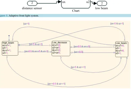
The Adaptive Front Light System as shown in Figure 1 has the ability to sense when a vehicle’s headlights should be turned on and off. This system controls the low beam and high beam based on the distance of the ob-stacles present on the path and using the street lamp detector. The high beam is definitely off when the street lamp is present since it is not necessary to use high beam in a well illuminated road. When there is no street light, high beam and low beam will be working according to the distance signal. The light dimming control system will be triggered if the barrier detected is within 5 m away. If an obstacle is over 5 m and within 50 m, the low beam angle adjustment will be on, and the headlamp angle will be adjusted according to the actual distance. When there are no obstacles detected within 50 m high beam and low beam will be at on state simultaneously. The stateflow for Adaptive Front Light System is shown inFigure 2 where transitions between different states are shown.
[image:3.595.94.535.407.708.2]Model Advisor checks for the requirements for MISRA-C [7] and ISO-26262 which are the standards for safety critical automotive electrical and electronic systems. It checks for blocks that are not recommended for production code generation as mentioned by MISRA-C. It also checks the state machine produced by Stateflow charts as mentioned by ISO-26262 standard. The model developed for Adaptive Front Light System successfully passed all the above mentioned tests. Thus a model for Adaptive Front Light System has been developed and tested with Model Advisor at model level which is found to be error free.
Figure 1. Adaptive front light system.
5. Design Verification
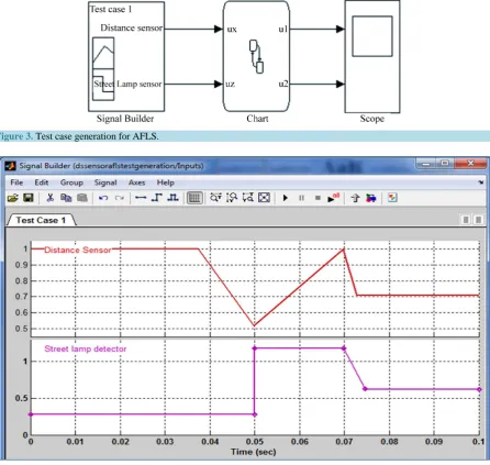
To test the system completely, first model coverage must be performed [8] on the system for which a test case has been generated. The first step in testing is test case generation which is shown inFigure 3 andFigure 4.
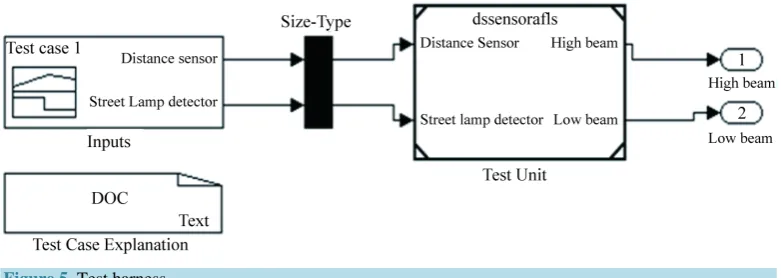
This test case has resulted in the decision coverage of 32% and condition coverage of 19% for the model de-veloped where decision coverage is a metric which measures the decisions paths covered in the model and con-dition coverage is a metric which measures the transitions covered in the model [9]. Thus the test case generated has covered only part of the model during the test. In order to have full decision coverage the next step in testing which is the test harness must be performed. SLDV is used to automatically generate the test harness for the model developed. In the harness generated, the signal builder block containing the test cases and a test unit which is the model to be tested are present. To create the test harness for the model developed the following command is used.
>>slvnvmakeharness (‘dssensorafls’)
The test harness is developed as shown inFigure 5.
[image:4.595.91.538.284.707.2]To save the already generated test case and to use it in the further testing process the following command is used.
Figure 3. Test case generation for AFLS.
>>dssensoraflslog1 = sldvlogsignals (‘dssensorafls_harness’) >>save existingtestcaseforafls. mat dssensoraflslog1
5.1. Combined Harness Using Simulink Design Verifier
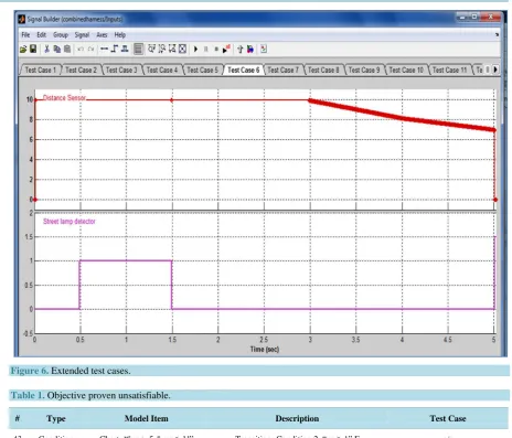
Thus an extended harness can be created for the model during the test harness step where the extra test cases generated help to increase the decision coverage of the model as seen inFigure 6. So that these test cases can be used during test analysis. For a test suite of a state chart to achieve full decision coverage all entry and exit paths through a state must be evaluated by test cases.
The model is tested in Design Error Detection mode to check whether there are any errors like division by zero or integer overflow errors present in the model developed and it took 17 s to do this analysis and no errors were found. When the Simulink Design Verifier is used in test generation mode, the transitions, conditions and state coverage are performed. The analysis time taken for this purpose is 11 s. Only one objective is proven un-satisfiable for this model out of 47 objectives and it is shown inTable 1.
The objective proven unsatisfiable may be due to the following reasons. 1) This often indicates the presence of dead-code in the model.
2) Other possible reasons can be inactive blocks in the model.
3) In rare cases, the approximations performed by Simulink Design Verifier can make objectives impossible to achieve.
Using the test cases generated from the test harness, model coverage is performed. Since all the decision paths have been covered for the model during this analysis 100% decision coverage is obtained. Condition coverage of 96% and Modified Condition/Decision Coverage of 92% is obtained. Each transition or input must be changed separately while keeping the remaining inputs fixed to achieve full Modified Condition/Decision Coverage. Thus the coverage report indicates how the behavior of the model can be exercised using the generated test cases. The statistical quality of the generated test suite and the parts of the model that were not tested properly can be identified. If a particular path through the model has no test generated for it, some of the test generation para-meters can be changed and the test generation step can be repeated. This is where it can be useful to use an ani-mation tool to investigate the behavior of the path in the model and decide whether the lack of tests is due to an error in the model, a normal feature of the model, or inadequate test generation. So to improve the coverage, an abstract test can be added for this path manually or give hints to the tool to get the desired results. This test har-ness coverage can also be done using another tool called Reactis.
5.2. Design Validation Using Reactis
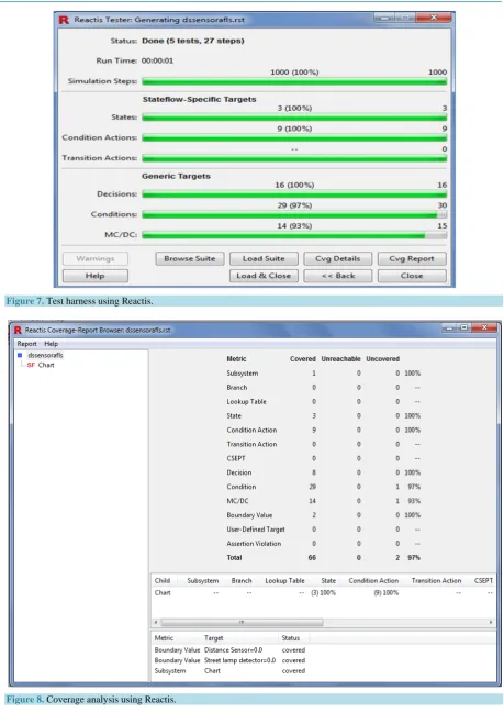
In Reactis automatic test case generation and the coverage analysis can be performed [10]. In order to limit the values that should be considered for the input, it must be specified in the sub range of base type in the type for port dialog box. Five tests are performed on the model with a total of 27 steps in them and the test suite gener-ated has a decision coverage of 100%, 97% condition coverage and 93% MCDC coverage for the model devel-oped as seen in Figure 7.
[image:5.595.118.509.577.716.2]The window as seen inFigure 8 shows that there is no unreachable code in the model but there are two un-covered codes.
Figure 6. Extended test cases.
Table 1. Objective proven unsatisfiable.
# Type Model Item Description Test Case
43 Condition Chart.“[ux > 5 & uz ≥ 1]” Transition: Condition 2, “uz ≥ 1” F n/a
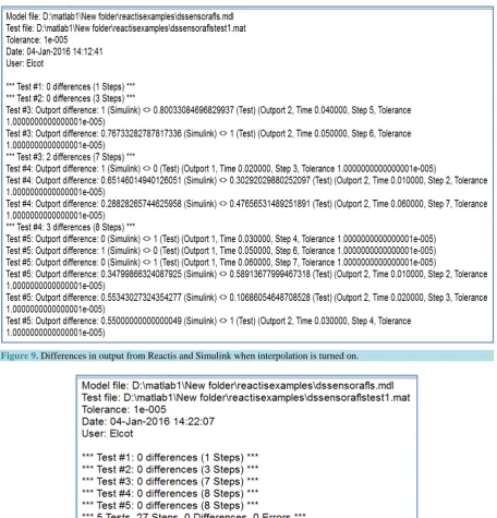
Reactis has generated five test cases where the first test case contains a single sample point input, the second test case has 3 sample points input, the third test case contains 7 sample points and the remaining two test cases contain 8 sample points. All these test cases produce correct results. When the tests developed using Reactis is made to run in Simulink, there is no error when interpolation is turned off and there will be some differences in the outputs generated in Simulink when compared to Reactis outputs when interpolation is turned on because in this case Simulink will sample inputs slightly differently than the original Reactis inputs which are shown in
Figure 9 and Figure 10.
6. Test Analysis Using SystemTest
Figure 7. Test harness using Reactis.
Figure 9. Differences in output from Reactis and Simulink when interpolation is turned on.
Figure 10. Differences in output from Reactis and Simulink when interpolation is turned off.
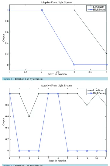
test results. In SystemTest the final process of test evaluation is performed where the test outputs will be com-pared with the expected outputs. During iteration 1 the input test vector is [0.01 9 0.3; 0.02 5 0.2; 0.03 1 0.6] and for iteration 2 [10 × 3] vector is taken as input and their results are seen inFigure 11and Figure 12. The out-puts generated in the SystemTest are same as the expected outout-puts from the model developed.
7. Conclusion
Figure 11. Iteration 1 in SystemTest.
Figure 12. Iteration 2 in SystemTest.
regu-late the speed of the vehicles upon seeing the unexpected obstacles while driving up or down in a mountainous terrain. Testing methods combined with Model-Based Testing are to be developed for this type of software which will be of an important value for a safer ride and upgrading the testing skills is needed.
References
[1] Pawel, S. and Gabriel, B. (2014) Model-Based Real-Time Testing of Embedded Automotive Systems. SAE
Interna-tional Journal, Passenger Cars—Electronic and Electrical Systems, 7, 337-344.
http://dx.doi.org/10.4271/2014-01-0188
[2] Toshiaki, K. and Masato, S. (2008) Technical Trends and Challenges of Software Testing. Science & Technology Trends, Quarterly Review, No. 29, October 2008, 34-45.
[3] Stürmer, I., Dziobek, C. and Pohlheim, H. (2008) Modeling Guidelines and Model Analysis Tools in Embedded Au-tomotive Software Development. Dagstuhl-Workshop MBEES, Modellbasierte Entwicklung eingebetteter Systeme IV, Schloss Dagstuhl, Germany, 7-9 April 2008.
[4] The MathWorks, Inc. (2015) Simulink Verification and Validation—User’s Guide, Version 2015b. The MathWorks, Inc.,Natick, Massachusetts.
[5] Reactive Systems, Inc. (2013) Testing and Validation of Simulink Models with Reactis. Reactive Systems, Inc., Cary, NC.
[6] Miller, M.D. and Ulaszek, R.R. (2012) Model-based Testing Using Branches Decisions and Options. US Patent No. 8225288.
[7] MISRA-C Guidelines (2007). http://www.misra.org.uk
[8] Justyna, Z., Ina, S. and Pieter, J.M. (2012) Model-Based Testing for Embedded Systems. CRC Press, Boca Raton. [9] Brett, M., Amory, W. and Jon, F. (2008) Best Practices for Verification, Validation, and Test in Model-Based Design.
The MathWorks, Inc., Natick, Massachusetts.
[10] Reactive Systems, Inc. (2015) Reactis—User Guide, Version 2015. Reactive Systems, Inc., Cary, NC.
[11] The MathWorks, Inc. (2010) System Test User Guide, Version 2010a. The MathWorks, Inc., Natick, Massachusetts.
Submit or recommend next manuscript to SCIRP and we will provide best service for you:
Accepting pre-submission inquiries through Email, Facebook, LinkedIn, Twitter, etc. A wide selection of journals (inclusive of 9 subjects, more than 200 journals) Providing 24-hour high-quality service
User-friendly online submission system Fair and swift peer-review system
Efficient typesetting and proofreading procedure
Display of the result of downloads and visits, as well as the number of cited articles Maximum dissemination of your research work