Improved Ladder Wave Modulation of Circulating
Current Suppressing Control Strategy of MMC
*
Pinggang Song, Yunfeng Li, Lina Wang
College of Electrical and Electronic Engineering, East China JiaoTong University, Nanchang City, Jiangxi Province, China Email: [email protected]
Received December, 2012
ABSTRACT
This paper partitions the arm current of MMC into uncontrollable current and controllable current. The former is deter-mined by the load that can’t be controlled by taking any control strategy. The later caused by the unbalanced total in-serted voltage of three arms can be controlled by some improved algorithms. The conclusion based on the researching the essence of circulating current is reached that change the number of the inserted sub-modules in each phase can sup-press the circulating current. Combined with the improved ladder wave modulation, a novel circulating current suppres-sion strategy particularly for the inverter station is developed. The improved strategy can adapt to load changes and re-duce the circulating current and output voltage THD of MMC ac terminals greatly without increasing any peripheral circuits. Finally, the simulation model of 100 submodules in each phase is constructed in MATLAB and the simulation results verify the correctness and effectiveness of the modified control algorithm.
Keywords: Modular Multilevel Converter; High Voltage Direct Current Transmission; Circulating Current; Module Changing Selection Algorithm; Double Frequency Negative Component
1. Introduction
As a novel topological structure of high voltage direct current transmission (HVDC), modular multilevel con-vert (MMC) has been developed for ten years due to the advantages in the high power application [1-4]. The first MMC project called “trans bay cable” between Pitts-burgh and San Francisco has been established by Sie-mens in 2010. Two hundred submodules per phase and
± 200 KV rated dc voltage and 400MW rated active power are the basic parameters of the project [5,6]. Spain and France have planed another powerful direct current transmission project, based on the MMC topology with the rated apparent power 1059MVA and dc voltage ±
320 KV, to operate in 2013 [7].
The advantages of MMC-HVDC are more superior compared to two levels VSC-HVDC, but the shortcom-ings must draw a big attention [8-11]. One of them is the double frequency negative circulating current in three phases, which decreases the service life of the converter and also increases power losses of the converter resulted in the decline operation efficiency [12]. Although new control strategy is constantly emerging, most of them can be partitioned into two categories: carrier phase shifted pulse width modulation (CPS-PWM) and capacitor
volt-age sorting algorithm [4,5,13]. All the control strategies proposed in the past ten years are based on the viewpoint that the total inserted submodules in each phase should not be changed. But in recent years, some papers have reported that the total inserted submodules is unnecessary to be constant,which gives an idea to improve the con-trol effects of MMC [13].
In this study, a circulating current suppression control strategy called module changing selection algorithm (MCSA) is proposed after modifying the traditional lad-der wave method [6] based on the traditional sorting al-gorithm from the aspect of engineering applying. The merits of the improved method are the ability to decrease the circulating current and the THD of output voltage of MMC obviously. While, the sampling period and proc-essing speed is demanded to be faster than the traditional control strategy. Stiffness dc voltage is needed to reflect the advantages of MCSA, which is particularly suitable for the passive network such as islet and offshore plat-form. Finally, a simulation model contained 100 sub-modules is constructed in MALTAB/SIMULINK, and the results show the correctness and effectiveness of the proposed algorithm.
2. Principle of MMC
*Project Supported by National Natural Science Foundation of China
(51167006); The special graduate student innovation fund of Jiangxi prov-ince (YC2012-S076).
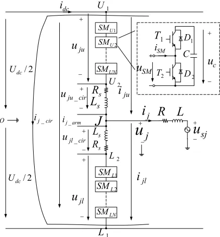
Rsand inductance Ls used to restrain the circulating
cur-rent imposed by the unbalanced total inserted voltage in three phases and the impacting current caused by the system faults [5]. The submodule in the upper right fig-ure of Figfig-ure 1 will be inserted to working no matter what the arm current direction is when T1 on and T2 off;
otherwise, the submodule will be cut-off when T1 off and
T2 on.
Letting the total inserted voltage between nodal points U1 and U2 is uju(j = a, b, c) and the nodal points between
L1 and L2 is ujl. uju_cir and ujl_cir indicate the voltage drop
of between Rs and Ls. According to the Kirchhoff’s
volt-age law [5,12]
_ _ _ _ 2 2 dc
ju j ju cir
dc
jl j jl cir
dc ju jl ju cir jl cir
U
u u u
U
u u u
U u u u u
(1)
Supposed that the upper arm and lower arm are sym- metrical, according to the Kirchhoff’s current law
_
_ 2
2
j ju j arm
j jl j arm
i i i i i i (2)
where, ij_arm is the current flowing through the j phase.
And it’s an uncontrollable dc current. Supposed that the total inserted submodules is N unchanged, the ideal volt-age of capacitor is
1 U SM 2 U SM UN SM 1 L SM 2 L SM LN SM
J
s R sL
s L s R O 2 / dc U 1 U 2 U 2 L 1 L jui
juu
jlu
cir ju u _ cir jlu _
u
jdc i jl
i
arm ji_
j
i
cir j i _ 1 T 2 T D2 [image:2.595.64.283.482.718.2]1 D C c
u
SMu
SM i sju
R
L
2 / dc UFigure 1. Basic structure of MMC.
0 dc
c
U U
N
(3)
The capacitor will be charged and discharged along with the direction of the arm current as the capacitance of the capacitor can’t be infinite in actual system, which makes the voltage of capacitor deviated from the ideal value of formula (3). Therefore, the unbalanced total inserted voltage of three phases make the arm current ij_arm no longer an unchanged dc current, in which
su-perimposes a double frequency current called circulating current [12]. Although the circulating current has no di-rectly influence on outer circuits, it magnifies the ripple of capacitor voltage and the system losses, and reduces the service life of the converter. Ignoring higher har-monics, the double circulating current of three phases fulfill
_ _ _ 0
a cir b cir c cir
i i i (4)
Equation (2) can be modified as
_ _ 3 3 2 2 j dc
ju j cir
j dc
jl j cir
i I i i i I i i (5)
where, Idc is the average value of idc. The voltage drop of
the upper and lower arm between equivalent resistance Rs
and inductance Ls are
_
_
ju ju cir s ju s
jl jl cir s jl s
di
u R i L
dt di
u R i L
dt (6)
Combined Equation (5) with (6), the output voltage of MMC ac terminal nodal point is
2 2 2
jl ju s s j
j j
u u R L di
u i
dt
(7)
Ignoring Rs because of Rs << ωLs, substituting equation
(5) into (6) to obtain the nodal points equation between U2 and L2
2 2
_
_ _ 2
j cir
U L ju cir jl cir s
di
u u u L
dt
(8)
Substituting Equation (8) into the first formula of Eq-uation (1), yields
_
2 s j cir dc ( ju jl)
di
L U u
dt u (9)
From Equation (9), it can be obviously seen that
_ 0
j cir
i at ideal assumption according to formula (3). Supposed that the dc voltage dc is sufficient stiffness in actual system, then Udc≠uju + ujl and Ls·dij_cir/dt ≠ 0
if keep the total inserted submodules N unchanged. So
ij_cir is a controllable current according to Equation (9).
The value of circulating current could get effectively controlled if the sum of the upper inserted voltage and lower inserted voltage could control nearly to the dc vol-tage Udc . For example, it does not have any big influence
on the output voltage of MMC showed in formula (7) if the upper and lower arm increases or decreases the same submodules at the same time as the voltage of capacitors in the upper and lower arm are controlled nearly identity. In doing so, it not only keeps the output voltage un-changed but also restrains the circulating current greatly. From the above analyses, it can reach the conclusion that the total inserted submodules of all the methods to re-strain the circulating current by using control algorithms are always fluctuating around N. Defining voltage mod-ulation and current modmod-ulation [14], respectively
/ 2 / 2
/ 3
o
dc
o
dc
U m
U I k
I
(10)
where Uo and Io are the amplitude of phase voltage and
phase current of MMC, respectively. Based on the for-mulas (1) and (7) and keep N unchanged, provides that the inserted modules of the upper and lower arm of phase A are
round( sin )
2 2
round( sin )
2 2
u
l
N mN
n
N mN
n
t
t
(11)
Where round(x) is the function to get the nearest inte-gral number [6].The formula of phase A of MMC ac ter-minal can be expressed as
0
round( sin ) 2
a c
mN
u t U (12)
3. Improved Modulation Method
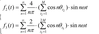
The total inserted submodules may be odd number, which gives an idea to decrease the output voltage THD of MMC ac terminals. By using this proper character, the traditional ladder wave for decreasing the THD of output voltage is modified this paper. Figure 2 shows the waveform of traditional and improved ladder waveform when N = 10 and m = 1. Blue line is the pure sinusoidal wave, red line is the traditional ladder waveform and green line is the improved ladder waveform. Without loss of generality, sinusoidal curve is f1(t), traditional ladder
waveform is f2(t) = round[f1(t)], improved ladder
wave-form is f3(t) = round[2f1(t)]/2. The Fourier analyses of the
traditional ladder waveform and improved ladder wave-form generated by f1(t) = mNsinωt/2in one cycle under
ideal condition are
2 2
3 3
2
1 1 2 3
1 1
4
( ) ( cos ) sin
2
( ) ( cos ) sin
M
i
n i
M i
n i
f t n
n n t
f t n
n n t
(13)where n is odd number. Might as well hypothesis N is even number, and M = round(mN/2).θi2 is the angle of level i2-1 jumping to level i2 in the first quarter cycle, and the same as θi3.θi2 and θi3 are θi2 = arcsin[(2 i2-1)/mN], i2 = 1,2,…,M and θi2 =arcsin[(i3-1/2)/ mN], i3 = 1,2,…,2M, respectively. Table 1 shows the rela-tionship between THD% and of the traditional ladder waveform and the improved ladder waveform when m = 1.
Rewriting the formulas (11) and (12) into the follow- ing equations after adapting the improved ladder wave- form modulation method
'
'
round( sin )
2 2
round( sin )
2 2
u
l
N mN
n
N mN
n
t
t
(14)
0
round( sin ) 2
c a
mN t U
u (15)
where, n’
u and n’l denote the inserted submodules of the
upper and lower arm, respectively. It appears alterna-tively between integer and non-integer at the same time of formula (14), which is different to the situation that the inserted submodules in the arm must be integer. The way to deal with the integer and non-integer will be dis-cussed in detail in the following sub-section.
5 10 15
-5 0 5
Value
s
e ladder wav l
traditiona
e ladder wav improved
2
i
1
2
i
2
i
3
i
0 /2 3/2 2
2 / ) 1 (i3
2 /
3
i
[image:3.595.354.518.88.145.2]wave reference
Figure 2. Traditional and improved modulation methods.
Table 1. Ideal THD of tradition and improved ladder wave modulation.
N 10 18 30 40 50 60
[image:3.595.363.479.299.386.2] [image:3.595.312.537.485.636.2] [image:3.595.307.537.690.736.2]4. Optimized Algorithm of Circulating
Current Suppression
Hundreds submodules of the commutation arms of MMC are needed to cascade for aiming at high power transmis-sion areas. Although the circulating current can achieve perfectly suppression when adopting CPS-PWM used in reference [5], it increases the hardware cost and the com-plexities of the control system since the number of the carrier is proportional to the number of the submodules. As mentioned before, all the control strategies that can restrain the circulating current in essence are to control the total inserted voltage nearly to the dc voltage.
The MCSA proposed in this paper can suppress the circulating current obviously and decrease the THD of arm current and the ripple of capacitor without increasing any peripheral hardware circuits. It has little influences on the output voltage but a huge impact on the circulat-ing current when the upper and lower arm increase or decrease the same number submodules at the same time. It’s feasible to restrain the circulating current without influence on the output voltage by choosing appropriate inserted submodules. Triggered at the reference ladder voltage stepping time, MCSA is a dynamic selection al-gorithm. It can achieve well suppression of circulating current according to formula (9) by choosing appropriate submodules to force the voltage between U2 and L2 to
[image:4.595.317.534.380.603.2]decrease at maximum possible. In doing so, it can main-tain the total inserted voltage nearly to the dc voltage, and this selection algorithm also can adapt to the load change automatically.
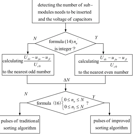
Figure 3 is the flow chart of MCSA. The basic princi-ple is as follows. Taking phase A as an examprinci-ple, sup-posing the desired output voltage of MMC is udesire =
mNUc0sinωt/2, so the actual output ladder is round
(mNsinωt)/2. The method to dispose the output of for-mula (15) changed between integer and non-integer is as follows. Calculating (Udc-uju-ujl)/Uc0 to the nearest even
number based on formulas (7) and (9) when formula (15) is integer; otherwise, calculating (Udc-uju-ujl)/Uc0 to the
nearest odd number based on formulas (7) and (9) when formula (15) is non-integer. uju and ujl are the total
in-serted voltage of the upper and the lower arm based on traditional sorting algorithm, respectively. In doing so, the number of the inserted submodules in the upper and lower arm when optimized sorting algorithm adopted can be modified as
round( sin )
2 2
round( sin )
2 2
u
l
N mN t
n
N mN t
n
2
2 N
N (16)
where, ΔN is the nearest even number or the odd number as mentioned in the previous analyses. It has to adopt the traditional sorting algorithm to provide pulses for each
submodule when the number of the inserted submodules is out of the actual boundary without redundant submod-ules.
5. Simulation Study
A simulation model to verify the correctness of the im-proved ladder wave modulation and MCSA is established in MATLAB/Simulink with the parameters Table 2 showed.
The comparison of traditional algorithm and the opti-mized MCSA based on the improved ladder wave modu-lation is showed in Figure 4, in which traditional sorting algorithm is adopted before 0.4s and the MCSA is acti-vated after 0.4s. Figure 4(a) is the voltage waveform of three phases of MMC ac terminals whose THD is 2.4% when tradition sorting algorithm adopted and 0.98% when improved MCSA activated. The reason why the values are difference to the 1.59% and 0.81% in Table 1 is that the simulation results are calculated in real situa-tion while the values in Table 1 are calculated in the ideal situation. Figure 4(b) is the three phases current. Figure 4(c) is the total inserted submodules of phase A. Fifty submodules are inserted constantly before 0.4 s,
N Y
N
Y N
? 0 0 16 formula
N n
N n
l u
) ( number odd nearest the to
g calculatin
0
c jl ju dc
U u u
U
number even nearest the to
g calculatin
0
c jl ju dc
U u u
U
?
integer is
(14) formula '
u n
capacitors of voltage the and
inserted be to needs modules
-sub of number the detecting
algorithm sorting
al tradition of pulses
algorithm sorting
improved of pulses
[image:4.595.318.527.640.736.2]Figure 3. Flow chart of MCSA.
Table 2. Basic parameters of simulation system.
Parameters values
UL-L/KV 37.5
Udc /KV 60
P/MW 60
PF 0.95
Uc0/KV 1.2
Ls/mH 10
[image:4.595.105.255.644.697.2]0.3 0.4 0.5 0.6 0.7 1.1
1.2 1.3
0.3 0.4 0.5 0.6 0.7
-50 0 50
0.3 0.4 0.5 0.6 0.7
-2 0 2
0.3 0.4 0.5 0.6 0.7
45 50 55
0.3 0.4 0.5 0.6 0.7
-500 0 500
0.3 0.4 0.5 0.6 0.7
-1 0 1
(a)
(c) (b)
(d)
(e)
(f) (s) Time
/K
V
u
ab
c
/K
A
i
abc
Mod
ule
s
/A
ia_cir
)/
K
A
(i
i
al
au
)/
K
V
(u
u
al
au
2.4%
THD THD0.97%
Figure 4. Waves of traditional and improved methods: (a) output voltage of MMC, (b) output current of MMC, (c) total inserted submodules of phase A, (d) circulating cur-rent of phase A, (e) the curcur-rent of upper and lower arm of phase A, (f) the voltage of capacitors of phase A.
while total inserted submodules fluctuated around fifty when MCSA is active. Figure 4(d) is the circulating current of phase A, in which the amplitude of circulating current is decreased greatly. The waveform of the upper and the lower arm current of phase A are showed in Fig-ure 4(e). After MSCA is adopted, the arm current does not contain a double frequency negative current. The capacitor’s voltage in the upper arm and the lower arm of phase A are showed in Figure 4(f), in which the voltage fluctuation in the capacitors greatly decreased after MSCA is activated and the control effect is obviously achieved.
Figure 5 is the main indexes simulation waveforms of MMC when a 10MW and 20Mvar inductive load in-serted at 0.3s. Figure 5(a), (b) are the voltage and cur-rent waveforms of MMC ac terminals, respectively. It can be easily seen from the waveforms that the voltage doesn’t change at steady, but the current accelerate to balance the power flow. Figure 5(c) is the waveforms of active power and reactive power. Figure 5(d) is the total
inserted submodules of phase A, in which the fluctuation range is relatively low because of under loading before 0.3s. With the load inserted, the fluctuation of capacitor voltage increased caused by the increased load current and the fluctuation range of total inserted submodules also increased. Figure 5(e) is the circulating current flowed through phase A. From the waveform, it can be known that circulating current achieves good suppression especially in heavy load situation. Figure 5(f) is the vol-tage waveforms of capacitors in the upper and the lower arm of phase A, from which no matter the load inserted or not the voltage of capacitors balance well.
5. Conclusions
Suppressing the circulating current needs to change the total inserted submodules in each phase is the conclusion achieved in this study according to the derived mathe-matical formulas. In order to decrease the output voltage’s THD of MMC, the traditional ladder wave modulation method is modified and the THD of the improved me-thod is smaller than the traditional meme-thod in ideal
0.2 0.3 0.4 0.5 0.6
-50 0 50
0.2 0.3 0.4 0.5 0.6
-2 0 2
0.2 0.3 0.4 0.5 0.6
-50 0 50 100
0.2 0.3 0.4 0.5 0.6
45 50 55
0.2 0.3 0.4 0.5 0.6
-200 0 200
0.2 0.3 0.4 0.5 0.6
1 1.2 1.4
(a)
(b)
(c)
(d)
(e)
(f) (s) Time
)/
K
V
(u
u
al
au
/A
i
a_
cir
Modu
le
s
/K
A
i
abc
/K
V
u
ab
c
Q/
Mva
r
P/
M
W P
Q
condition. Combined with the improved ladder wave modulation, a novel control strategy, particularly suits for the inverter station for power applying of islet and off-shore platform, is proposed to suppress the circulating current flowing within the six arms and decrease the output voltage’s THD of MMC.
REFERENCES
[1] A. Lesnicar and R. Marquardt, “An Innovative Modular Multilevel Converter Topology Suitable for a Wide Power Range,” IEEE Power Technology Conference Pro-ceedings, Bologna Italy: IEEE, 2003, p. 6.
[2] A. Antonopoulos, L. Angquist and H. P. Nee, “On Dy-namics and Voltage Control of the Modular Multilevel Converter,” European Power electronics and Applica-tions Conference, Barcelona Spain: IEEE 2009, pp. 1-10. [3] M. Glinka and R. Marquardt, “A New Ac/Ac Multi- level
Converter Family,” IEEE Transactions on Industrial Electronics, Vol. 52, No. 3, 2005, pp. 662-669.
doi:10.1109/TIE.2005.843973
[4] M. Hagiwara, K. Nishimura, “A Medium Voltage Motor Drive with a Modular Multilevel PWM Inverter,” IEEE Transactions on Power Electronics, Vol. 25, No. 7, 2010, pp. 1786-1799. doi:10.1109/TPEL.2010.2042303
[5] M. Hagiwara and H. Akagi, “PWM Control and Experi-ment of Modular Multilevel Converter,” inProceedings IEEE Power Electronics Specialists Conference, Rho-des Greece, 2008, pp. 154-161.
[6] Q. Tu and Z. Xu, “Impact of Sampling Frequency on Harmonic Distortion for Modular Multilevel Converter,” IEEE Transactions on Power Delivery, Vol. 26, No. 1, 2011, pp. 298-306. doi:10.1109/TPWRD.2010.2078837
[7] J. Peralta and H. Saad, “Detaled and Averaged Models for a 401-level MMC-HVDC System,” IEEE Transactions on Power Delivery, Vol. 27, No. 3, 2012, pp. 1501-1508. [8] S. Allebrod, R. Hamerski and R. Marquardt, “New
Transformerless, Scalable Modular Multilevel Converters for HVDC Transmission,” in Proceedings IEEE Power Electronics Specialists Conference, Rhodes Greece, 2008, pp. 174-179.
[9] R. Marquardt, “Modular Multilevel Converter:An Uni-versal Concept for HVDC-networks and Extended DC-bus-applications,” International Power Electronics Conference (IPEC), Sapporo Japan:Institute of Electrical and Electronics Engineers,2010, pp. 502-507.
[10] S. Robner, S. Bernet and M. Hiller, “Modeling, Simula-tion and Analysis of a Modular Multilevel Converter for Medium Voltage Applications,” IEEE International Con-ference on Industrial Technology (ICIT), Viña del Mar Chile:Institute of Electrical and Electronics Engineers, 2010, pp. 775-782.
[11] S. Rohner,S.Bernet,M. Hiller,etc., “Analysis and Simulation of a 6 Kv,6 MVA Modular Multilevel Con-verter,” 35th Annual Conference of IEEE on Industrial Electronics, Porto Portugal:Institute of Electrical and Electronics Engineers,2009, pp. 225-230.
[12] Q. Tu, Z. Xu and L. Xu, “Reduced Switching Frequency Modulation and Circulating Current Suppression for Modular Multilevel Converters,” IEEE Transactions on Power Delivery, Vol. 23, No. 3, 2011, pp. 2009-2017. [13] Z. X. Li, P. Wang and H. B. Zhu, “An Improved Pulse
Width Modulation Method for Chopper-Cell-Based Modular Multilevel Converters,” IEEE Transactions on Power Electronics, Vol. 27, No. 8, 2012, pp. 3472-3481.