5
VIII
August 2017
Grid Synchronization of a Microgrid with
Renewable Energy Sources and Storage Assisted
with Controller Area Network
Tandava Anjali1, Mrs. V. Sai Geetha Lakshmi(Asst. Professor)2
1,2Dept. of Electrical and Electronics Engineering
P.V.P.Siddhartha Institute of Technology, Kanuru, 520 007, Vijayawada, India
Abstract: Microgrids are rising as an vital constituent of massive-scale smart grids. They are equipped with the controls necessary for managing the operation in islanded or grid connected mode and serve the loads with clean, reliable, and uninterruptible power. CAN (Controller Area Networking) based totally power management system discloses the minimization of cost in automation manage for power supply. right Here an hybrid model of sources and their individual overall performance was accumulated, validated the use of three strength sources (PV array, PEMFC, battery) connected to grid beneath non-local masses. right here the tripping time at 0.1 sec must be sharp and much less time response become required to connect from islanded mode to Grid connected mode. There individual sources were recognized at this phase with high reaction time while compared with the hybrid model. CAN acts like information transfer among controlling inverter phase and at the grid aside from all other obligations of it. In this Research paper controlling modes were advanced the usage of PLL(Phase Lock Loop) PI controller and additionally examined with PLL PID manage to affirm the enhancing sharpening time reaction whilst changing from islanded mode to grid connected mode is done by using MATLAB/SIMULINK software.
Key phrases: PEMFC,PV array, strength control, battery, PI controller, PID controller, , CAN.
I. INTRODUCTION
Micro grids are gaining extensive popularity as they possess all the necessary properties to constitute a major building block of the envisioned smart grid. The adverse effects of high penetration of Renewable Energy Sources (RES) like solar PhotoVoltaic (PV), PEMFC(Proton Exchange Membrane Fuel Cells), wind, etc. on the stability of the existing grid network has been elevating a first-rate difficulty. With the appearance of micro grids this issue has subsided. Micro grids are capable of presenting secure, uninterrupted, and high quality power to the loads while facilitating Smooth integration of the RES.
Black-start, Grid Synchronization (GS), stability, protection, and energy control during island mode of operation are some of the essential problems [1] with micro grids that are being drastically investigated. The default operating mode of micro grids is the “grid connected mode” wherein they are tied up with the main grid. Micro grids want to alternate strength (import or export) with the primary grid that allows you to stability the generation and local load demand. As in line with IEEE-1547-2003, an anti-islanding scheme has to de-energize the sources inside 2 s of the prevalence of an islanding occasion [2]. Whereas as in step with IEEE-1547.4, the micro grid is permitted to preserve operation in island mode to deliver uninterrupted power to the local loads supplied it meets the essential voltage and frequency stability standards [3]. all trough this phase, if the grid restores, then it's miles applicable to switch again to the grid connected mode. in an effort to switch between the two running modes, it is essential to offer smooth and transient loose transition so that the masses do not enjoy any disturbance. Thus, there is a need to have the micro grid equipped with a sturdy transition management system comprising both islanding and GS schemes.
For any smart grid implementation, communication among various automation components is critical. Power measurement devices must talk to real-time control components across the entire power generation, transmission and distribution spectrum. All automation components must connect to higher level Supervisory Control And Data Acquisition (SCADA) systems, and these SCADA systems must link to one another [14].All of these connections and linkages require open communication systems, often based on Ethernet and the Internet, especially for new installations and upgrades to existing systems.
because Ethernet used as a common communications hardware protocol.. Fifth and last, on-going maintenance and operation costs are reduced because many in the industry are familiar with Ethernet and the Internet [4]. Most of the existing North American power grid operates in a centralized manner, with power flowing from generation facilities to the grid for Transmission and Distribution (T&D) to the end user. Substations are the brains of T&D systems, and connections among substations and generation facilities are often limited in terms of bandwidth and real-time performance [5-8].
These limited connections make it hard for utilities to balance generation and demand in real-time, especially with the advent of renewable and distributed energy generation. Some renewable typically solar and wind power are hard to accommodate because of their inherent intermittent, unpredictable and widely varying energy output [12].
Distributed energy resources are typically small scale power generation facilities, often renewable but in other cases conventional sources like gas turbines and diesel generators. These resources are often not under the direct control of the utility, and their power output varies widely with little or no relation to overall demand [20].
An intelligent smart grid relies on real-time, high-bandwidth, two-way open communications to control and monitor power flows. These communications make the smart grid viable, but also open it to cyber attack. Smart grid technologies will introduce millions of new intelligent components to the electric grid that communicate in much more advanced ways than in the past, namely two-way va open protocols.
Any GSA should be validated under the following conditions: Harmonic or noise rich grid voltage signals;
Unbalanced grid voltages;
Frequency and voltage variability in weak grid conditions; Phase angle jump resulting due to voltage sags;
Transient conditions resulting in voltage dips or swells.
GS strategies may be widely categorized as communication less techniques [6]–[12] and communication assisted techniques [13]– [15]. GS strategies basically offer the segment facts of the grid voltage, that's then used to create the template that allows synchronization of the manipulate parameters either with the gadget voltage or the system current. Communication assisted GSA commonly uses the worldwide positioning machine (GPS) or community time protocols (NTP) for subsystem synchronization after which for micro grid synchronization however includes high cost for implementation.
This paper proposes a easy, low price, and reliable GS Technique based totally on controller location community (CAN) verbal exchange.CAN is a strong fault tolerant multiport serial communication network capable of offering 1 Mb/s data rate .The proposed scheme is primarily based on CAN verbal exchange among controlling inverter phase and at the grid aside from all other obligations of it.
II. GRIDSYNCHRONIZATIONOFAMICROGRID
Figure 1: Controller With CAN structure
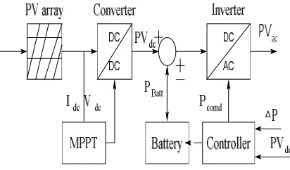
A PV model with inverter control is shown in Fig.2. It consists of PV geared up with MPPT method [9], a battery and a bidirectional inverter. here PVdc and PVac are the dc and ac powers of photovoltaic farm respectively; PBatt is the battery active power; Pcomd is the
output electricity command; Idc and Vdc are the dc contemporary and voltages respectively; ∆P is an energetic power go with the
flow deviation strength.
In Fig.2 PV array is the mixture of both collection and parallel connection of PV modules. equal circuit of PV module is shown in Fig.3. PV module is represented through a contemporary source, diode, shunt resistor and series resistor. right here shunt resistance represents resistance of leakage present day, series resistance represents inner resistance of PV cells.
Fig. 2. PV model with inverter control From KCL and KVL the Idc and Vdc are given by way of
Idc = Ig – ID – VD/Rp (1)
Vdc = VD – RsIdc (2)
In above equations Ig is the generated present day from insolation, identification, VD are the diode contemporary and voltage respectively. Rp, Rs are the shunt and collection resistance respectively.
Then the output power of inverter is given by
PVdc = Vdc .Idc. (3)
On this paper PV equipped with most electricity point monitoring (MPPT) approach. So, the maximum strength track from PV and again fed to the dc-dc converter. The dc-dc converters step up the energy and fed to inverter. here inverter is a bidirectional one. It Converts dc to ac strength supply to the load and take in ac strength from the system.
consequently ac power is given by
SOLAR PANEL BATTERY
PEFMC
VOLTAGE AND CURRENTCON TROLLER
[image:4.612.213.419.381.502.2]PVac = PVdc (4)
Fig. 3. Inverter with output strength control
In Fig.2 the inverter is represented with the aid of a primary order transfer function with the output power manage. So the output energy can be controlled by means of the power command (Pcomd). primarily based on the electricity command the battery can be charging or discharging.
[image:5.612.176.417.74.176.2]A. PI-Controller
Fig. 4 indicates the block diagram of the proposed PI control scheme for the energetic power filter. The DC side capacitor voltage is sensed and compared with a reference voltage. this mistake e = Vdc, ref −Vdc on the nth sampling on the spot is used as input for PI controller. the error signal is surpassed thru Butterworth layout based Low pass filter (LPF). The LPF filter out has cut-off frequency at 50 Hz that may suppress the better order additives and permits handiest fundamental components. The PI controller is estimate the significance of peak reference present day Imax and manage the dc-facet capacitor voltage of voltage supply inverter. Its switch function is represented as,
H (s) = Kp+ KI/S
[image:5.612.155.460.462.634.2]B. PID Controller
Fig 4 shows the block diagram of the proposed Proportional Integrator by-product (PID) control scheme of an energetic electricity clear out. the error e = Vdc,ref −Vdc on the nth sampling immediate is used as input for PID controller. the mistake sign is passed through LPF; that can suppress the better order components and skip most effective the essential element.
Fig.4, Block diagram of the PLL with PI and PID Controller
in which, KP is the proportional consistent that determines the dynamic response of the Dc-side voltage manipulate, KI is the integration the derivative of the error representing the tendencies. The controller is tuned with proper benefit for estimating the importance of peak reference modern-day Imax and control the dc-side capacitor voltage of inverter. the peak reference contemporary improved with PLL output determines the favored reference present day.it's far a popular approach of coping with systems related to uncertainty, unmodeled dynamics and wherein human revel in is needed. It provides a easy way to reach a specific solution based upon vague, vague, noise, or lacking statistics [10]. This method to govern troubles mimics how someone would make a choice such faster. the main application of benefit scheduler is the tuning of PID controller gains. by way of the collection of IF-THEN policies the gain scheduler adjusts the gains of controller over one of a kind running conditions. however the PID controllers are used because of its easy and realistic structures. however these are not giving any excellent overall performance over a wide range of running conditions. in this paper the machine is used to track the PID controller profits as PID profits.
Schematic diagram of gain scheduler is as shown in The manage signal of a PID controller is given by means of Pcomd = KP e(t) + KI∫ e(t) dt + KD de(t)/dt (5)
where KP, KI, KD are the proportional, fundamental, by-product profits of PID controller respectively .and e(t) is the manage signal.by using adjusting the power command (Pcomd) of the inverter the control sign of a classical PID controller is generated. In ∆P and PVdc are the inputs of the inference system and Ks1 and Ks2 are the size factors, KPF, KDF, KIF are the outputs. here PVdc
is error and ∆P is the alternate in error, KPF, KDF, KIF and therefore little scope for variations of ω(t) is described. however, if you want to allow the ω(t) in transient situations, ω(t) might be selected big enough. If PLL is following the time period + , then + − term is close to zero and sin( + − ) = ( + − ) . for this reason (24) can be simplified as follows:
= ( )( + − ) (6)
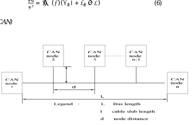
[image:6.612.155.461.363.562.2]C. Control Area Network(CAN)
Fig 5. CAN block diagram
Fig 6. CAN contains built in priority for messages to avoid conflict
The detailed scheme of the proposed control and communication interface for the fuel cell MS is shown in Fig. 7.similar interface is available with other MS.To synchronize multiple MS with each other to form the microrid bus and then to connect the same to the main grid ,it is necessary that each of the MS acquires or receives the grid voltage template at a fast rate .
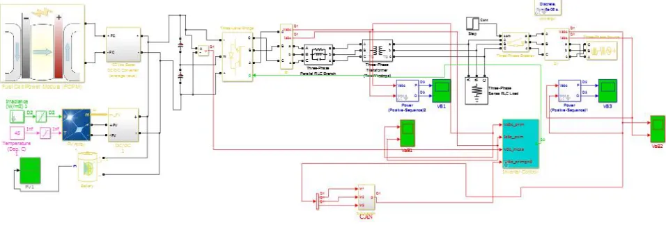
. Fig 7. MPC control implementation with CAN III. MATLAB/SIMULINK RESULT
[image:7.612.71.549.527.689.2]The proposed model is simulated in MATLAB 2015b/SIMULINK environment.Individual Micro source also analyzed
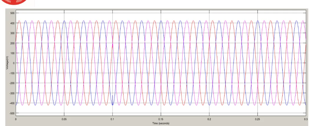
(a)
(b)
Fig9: Simulation results showing the Hybrid Model (a) smooth transition from standalone mode to grid connected mode and (b) sharing of active and reactive power between grid and micro grid during these two operating modes and the transition
Phase ‘R’ Voltage/Current Phase ‘Y’ Voltage/Current Phase ‘B’ Voltage/Current
Stand Alone Mode Grid Connected
Active Power (W) Reactive Power (VAR)
Fig10:CAN Transfer output to the inverter controller Table 1.Case study
Time took to shift mode from isolated to grid connected mode Table 1.
IV. CONCLUSION
The mode transition management of a microgrid, dominated by RES is quiet complex, especially while transitioning from islanded mode to grid connected mode. The nondispatchable nature of most of the RES makes the task more difficult. In
order to minimize the transition transients, it is necessary to synchronize all the MS simultaneously with the main grid. To adjust the maximum voltage in grid connected mode sharp response was required this made possible by using hybrid energy source and current voltage pi, pid with PLL controllers implemented to adjust the voltage gain and current at inverter mode. It helps in adjusting voltage from standalone mode to grid connected mode all these were monitored using automation tool and data transferred for monitoring using CAN. The resultant transients observed during the transition phase are very low Time took to shift mode from isolated to grid connected mode is 0.1000001 sec. A constant outcome was obtained in active and re-active power.
REFERENCES
[1] J. A. P. Lopes, C. L. Moreira, and A. G. Madureira, “Defining control strategies for microgrids islanded operation,” IEEE Trans. Power Syst.vol. 21, no. 2, pp. 916–924, May 2006.
[2] IEEE Standard for Interconnecting Distributed Resources With Electric Power Systems, IEEE Standard 1547, Jul. 2003.
[3] Guide for Design, Operation, and Integration of Distributed Resource Island Systems With Electric Power Systems, IEEE Standard 1547.4,2011.
[4] H. Farhangi, “The path of the smart grid,” IEEE Power and Energy Magazine, vol. 8, no. 1, pp. 18–28, 2010.
[5] S. M. Amin and B. F. Wollenberg, “Toward a smart grid,” IEEE Power and Energy Magazine, vol. 3, no. 5, pp. 34–41, 2005. · ·
[6] W. K. Park, C. S. Choi, I. W. Lee, and J. Jang, “Energy efficient multi-function home gateway in always-on home environment,” IEEE Transactions on Consumer Electronics, vol. 56, no. 1, pp. 106–111, 2010.
[7] M. Jahn, M. Jentsch, C. R. Prause, F. Pramudianto, A. Al-Akkad, and R. Reiners, “The energy aware smart home,” in Proceedings of the 5th International Conference on Future Information Technology (FutureTech '10), pp. 1–8, May 2010.
[8] D. Niyato, L. Xiao, and P. Wang, “Machine-to-machine communications for home energy management system in smart grid,” IEEE Communications Magazine, vol. 49, no. 4, pp. 53–59, 2011.
[9] D. Y. Nagesh, J. V. Krishna, and S. S. Tulasiram, “A real-time architecture for smart energy management,” in Proceedings of the Innovative Smart Grid Technologies Conference (ISGT '10), pp. 1–4, January 2010.
PFEMC SOLAR HYBRID PI 0.100008 0.100012
-
[10] P. Kulkarni, S. Gormus, Z. Fan, and B. Motz, “A mesh-radio-based solution for smart metering networks,” IEEE Communications Magazine, vol. 50, no. 7, pp. 86–95, 2012.
[11] E. Pallotti and F. Mangiatordi, “Smart grid cyber security requirements,” in Proceedings of the 10th International Conference on Environment and Electrical Engineering (EEEIC '11), pp. 1–4, May 2011.
[12] A.R. Metke and R. L. Ekl, “Security technology for smart grid networks,” IEEE Transactions on Smart Grid, vol. 1, no. 1, pp. 99–107, 2010.
[13] EPRI, Report to NIST on Smart Grid Interoperability Standards Roadmap, EPRI, Gaithersburg, Md, USA, 2010.
[14] R. H. Lasseter and P. Paigi, “Microgrid: a conceptual solution,” in Proceedings of the IEEE 35th Annual Power Electronics Specialists Conference (PESC '04), pp. 4285–4290, June 2004.
[15] NanoCatGeo, “NanoCatGeo project,” https://sites.google.com/site/nanocatgeo.
[16] Acta, “Hydrogen generators and fuel cells systems,” http://www.actagroup.it.
[17] L. Fanucci, S. Saponara, and A. Morello, “Power optimization of an 8051-compliant IP microcontroller,” IEICE Transactions on Electronics C, vol. E88, no. 4, pp. 597–600, 2005.
[18] S. Saponara, E. Petri, L. Fanucci, and P. Terreni, “Sensor modeling, low-complexity fusion algorithms, and mixed-signal IC prototyping for gas measures in low-emission vehicles,” IEEE Transactions on Instrumentation and Measurement, vol. 60, no. 2, pp. 372–384, 2011. · ·
[19] E. L. Quinn, Privacy and the New Energy Infrastructure, Social Science Research Network (SSRN), 2009.
[20] T. Flick and J. Morehouse, Securing the Smart Grid: Next Generation Power Grid Security, Syngress, 2010.
[21] ZigBee, The ZigBee Specification Version 1. 0, ZigBee Alliance, San Ramon, Calof, USA, 2007.
[22] M. Zeifman and K. Roth, “Nonintrusive appliance load monitoring: review and outlook,” IEEE Transactions on Consumer Electronics, vol. 57, no. 1, pp. 76– 84, 2011. · ·