5
II
February 2017
Technology (IJRASET)
Design of Robot Machine Control by Cell Controlling
Device
Sangram B. Dhepekar1 , Prof. Jaya G Borke2
1
P.G.Student, 2Professor
1,2
Department of Mechanical Engineering, S. S. Agnihotri College Of Engineering , Wardha , India .
Abstract: Internal Robot Machine control by Remote controlling Device is the creative concept in pipeline design .This concept are used in various applications in Thermal Power Plant , in Pipeline Industries and in Manufacturing sector. Scale formation created inside the pipelines which are very dangerous and serious problem in thermal power plant, water treatment plant, in drainage industries etc. This scale formation creates the tremendous expense. To remove scale formation, choke up and avoid the problem expense go to high. To cut the expensive and costly pipeline or change the pipeline create highly expense to company. In this paper the simple design of internal cleaner robot carry the occupant safety in a crash environment and chokup reduction is considered. Design will provide an additional way to nullify some of above issues.
This is the internal cleaner robot of pipeline but it can use in various areas for cleaning and removing of tiny particle. Design Of Robot Machine Control By Cell Controlling Device this is the main concept to create the model . This is multi-mechanism system where we can change the number of cutting tools as per our application. This paper gives the idea about how to clean the internal surface in pipeline The big machinery have not capacity to go inside in the small pipeline & cannot easily portable from one place to another place. This machine is very small, light and easy to handle. Aim of this project is to perform design to save the money and materials of company. It is very useful to improve the efficiency and performance of fluid flowing capacity of fluid materials.
Keywords: Cell Device, Electro-Mechanics , Robot, Sensor, Motor, Spindle, Wheel, Microcontroller, Coil, Condenser etc.
I. INTRODUCTION
In many industries such as Water treatment plant , thermal power plant and pipe industries have some problem about internal cleaning of pipeline which carries more expense ,more construction and repairing maintenance created problem towards company. To minimize this type of problems we have solution that how to solve these type of problem by the help of Design .
Cleaning of pipeline created the danger problem and challenging aspect. For this problem, we are taken following steps with the help of Robotics engineering. Following are the basic information about locomotive robot mechanism.
Today, however, we can build small mobile robots with numerous actuators and sensors that are controlled by inexpensive, small, and light systems that are carried on-board of the robot. There has been a tremendous increase of interest in mobile robots. Not just as interesting toys or inspired by science fiction stories or movies, but as a perfect tool for engineering education.
This paper describes the in-pipe cleaning system used by the robot, its configurations, mechanical properties, kinematics and
preliminary cleaning test results. This new approach for in-pipe cleaning mechanism, a single cylindrical robot going to use. Blade mounted on one of on the spindle, while a drive wheel is located with the shaft, by the help of gear system, enabling linear movement to the entire cleaning system with high resolution steps in the cylinder. Additionally, our approach prevents the cleaning mechanism from damaging the pipe, reacting to overcome any excessive force. To do so, its mechanical arrangement includes two type of motors system in the housing of cylinder to react when working with a cleaning tool over corroded surfaces, enabling the tool to retract if vibrates or jumps back, instead of passing all these unwanted forces to the pipe.
Fresh water pipelines are damages due to aging, excessive traffics and geological changes. Resulting from these damages, the pipe-joints may not be completely hermetic and water loss along the pipeline may occur. Leakage is not only a problem in terms of wasting an important resource, it also results in an economic loss in form of damages to the supplying system and to foundations of roads and buildings too. The installation or replacement of pipelines implicates high cost and use of heavy machinery, such as cranes , big cutter ,weeding machine etc. Due to this new design we are ready to clean the pipeline with the help cutter by robot controlling system in various application.
Technology (IJRASET)
solutions available. Nevertheless, to substitute skilled human operators, pipe redevelopment requires mechanisms with high degree of mobility. This is able to move along in the pipeline, overcoming obstacles, extreme environments, and with high accuracy clean and repair specific areas of the pipe .
Followings are the some required steps for creating design . Step 1: Requirement of company and problems of customer. Step 2: Root cause of problem..
Step 3: How to remove the problem.
Step 4: Find the maximum output and save the money. Step5: Less movable parts and minimum weight. Step6: This is specified for inside of pipe. Step 7: Must be move in straight line. Step 8: Must be return back with linear way .
Step 9: Cutter must be adjustable as per requirement .
A. Assembly Part
Following Are The Assembly Part Of Internal Cleaner Robot
For making of the design model, number of mechanical , electrical .and electronics part are necessary to assessable the model. Register Coil Transistors P.F. Diode IC Condenser Motor Switch Signal Sensor Cylindrical Pipe
Two One Side Open Cap
Four Wheel Modified Plate
[image:3.612.214.400.533.729.2]Tools Cell Panel Cell Panel
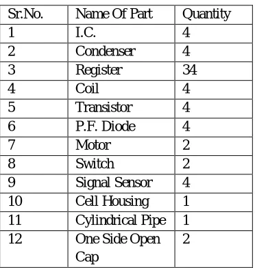
Table 1: Parts of Robot
Sr.No. Name Of Part Quantity
1 I.C. 4
2 Condenser 4
3 Register 34
4 Coil 4
5 Transistor 4
6 P.F. Diode 4
7 Motor 2
8 Switch 2
9 Signal Sensor 4 10 Cell Housing 1 11 Cylindrical Pipe 1 12 One Side Open
Cap
Technology (IJRASET)
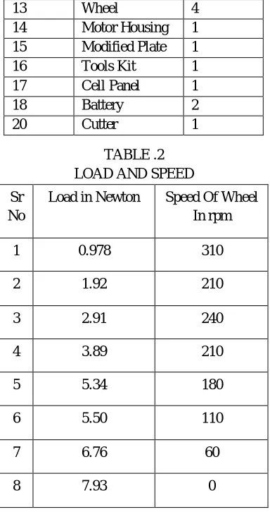
Motor HousingTABLE .2 LOAD AND SPEED
Sr No
Load in Newton Speed Of Wheel In rpm
1 0.978 310
2 1.92 210
3 2.91 240
4 3.89 210
5 5.34 180
6 5.50 110
7 6.76 60
8 7.93 0
B. Design And Calculation Of Robot Machine
Followings are the basic information about Robotics Machine which are required for design aspects.
1) Cylinder: Length of cylinder = 250 mm Outer dia of cylinder =64 mm
Inner dia of cylinder =60mm
2) Wheel: Outer dia of wheel =20mm Shaft whole =1.21 mm
3) Cup: Outer dia of cup =65mm Inner dia of cup =64mm
4) Battery: Current 1000mA Voltage capacity 1.2 to 12 volt Parallel type
5) Cutter : Cutter length 1 =35 mm Cutter width1 =1.21 mm
Cutter length 2 = 64 mm Cutter width 2 = 2.1mm Cutter length 3 =77 mm
6) Motor:Motor speed variation = 12.5% Speed of motor 1= 300 rpm
Speed of motor 2 = 2000 rpm
13 Wheel 4
14 Motor Housing 1 15 Modified Plate 1
16 Tools Kit 1
17 Cell Panel 1
18 Battery 2
Technology (IJRASET)
7) Sample Of Scale : Thickness of scale = 3.51 mm Inner scale dia =75 mm
Outer scale die =84mm
Mean dia of scale =(Outer dia +Inner dia)÷2……… (1.1) =(78+84)÷2
= 81.5 mm
Length of scale =2πr ………. .… (1.2) =2×π×4O.75
=256.03 mm
Area of scale = length of scale×thickness of scale .. (1.3) =256.03×3.51
=896.1 mm2
8) Stresses: Maximum force to cut the scale sample 1 = 2.4 N
Stress =Force÷Area ……… (1.4) Selecting cross section area= thickness x length
=3.51 x 7 =24.5mm2 Cutting stress = 2.4÷24.5
=97.95 x 10 -3 N\mm2
9) Depth Of Cut:
T=[ Max dia of scale – Inner dia of scale]÷2…………(1.5) =[85-78]÷2
=3.5mm
10) Current Voltage Relation:
Current = 1000 to 4000mA Voltage= 1.2 to 12 volt
Resistace = v÷i……… (1.6) =1.2÷40003×10-04Ω
11) Electrical Power:
Power = i×v……… (1.7) =4000x1.2
=4800mAV
C. Images
Following is the wireframe structure which shows the different parts of Robot Cleaner Machine .
Technology (IJRASET)
We are provided the four wheels which has same dimensions for the purpose of trasmitting the motion in linear way .
Fig.2. View of wheel .
This is the Cyindrical Pipe which have two shaft for wheels support to perform the rotory motion .
Fig.3.View of cylinder .
This two type of different cups are provided externally to the cylinder on opposite side . One cup for the cutter support and another for rear support.
Technology (IJRASET)
This figure shows the 3D Model of Robot Machine which is now ready to perform the different type of operation to cut the material inside the Pipeline with Remote controlling Device
Fig.6.Image of machine
II. CONCLUSION
Following are the conclusion carried out by the help of design and practical observations
In this Paper I made the some changes to the design variables of the internal cleaner robot. By setting the goal of design we have selected the different value and result of machine in various application towards removing scale materials from the internal areas. In this paper we presented the new approach in-pipe cleaning mechanism which was presented by us .We also perform and compared the cleaning systems with old cleaning systems which was handled by manually .
The presented mechanism improves the state-of-the-art in multiple aspects, such as enabling the cleaning tool to precisely step in the pipe surface.
By using different type of cutting tools which are applicable on the problems we said that this is actually worked in processes. This is the single cylindrical configuration mechanism in the robot , and protecting the pipe from unwanted forces caused by the cleaning tool from its integrated suspension and drive wheel configuration.
actuator is located on one of the rotating element in the central axis as the classical model.
While rotating the cutter removes the corrosion of the inner side of pipe. A cleaning tool as cutter mounted on the wheel spindle in front of cylinder .
Removing unwanted material and Cleaning results from mechanism are presented and compared to human performances so more. Control method for moving robotics in closed are as based on creation and obstacle avoidance is proposed with the help of remote controlling device .
Technology (IJRASET)
robotics design hence plays the important role in industries and manufacturing as well as service systems area.
III. FUTURE SCOPE
There is much scope of robot cleaner in pipeline for internal cleaning as well as to removing scale formation in internal periphery This project are useful to improve the drainage system of water , fluid, and other soluble liquid , due to this increasing efficiency of pipeline and avoiding the extra scrap of material .
This project is also use to save the extra expense towards cutting the pipeline due to choke up and corrosion To remove the rust and dust particle from the various compact areas this machine carry the more advantages .This is suitable for remote distance and can be increase or decrease the capacity of remote sensor .
This project are having so many scope in gas pipe line .When pipeline creates or supply the harmful gases that time this robot machine will play the important role to clean internal area with safe creation.
IV. RESULTS
Following are the results are which are obtained by this design
In pipe robot are used to clean the inner dent , rust and other unwanted material from the pipe in effective way.
By the use of rotating function of wheel and cutting tool with specified design we get applicable result with good output . We have created this design to reduce the cost of material , man power and machine .
Robot operated in straight way as in linear direction and controlled by cell very easily.]On application and different scale we must ready to change the cutter of required size.
This cleaner machine controlled by cell controlling device from remote distance
V. ACKNOWLEDGMENT
It gives us immense pleasure to present our research paper titled with Design of Robot Machine Control By Cell Controlling Device.We are thankful to our honourable Co-ordinator , HOD and our Mechanical Engineering Department .The authors greatly acknowledge the support provided by Professor Sandip Jaware, Professor. Jaya G. Borke SSPCE Wardha and our friends.
REFERENCES [1] B.D. Shiwalkar “ Design data for machine elements” Denett & Co Jan 2013.
[2] Robin R Murphy “Introduction To Ai Robotics”, The Mit Press London 2000
[3] Roland Siegwart, Illah R. Nourbakhsh “ Introduction To Autonomous Mobile Robots” London 2004 [4] IbrahiZeid “Mastering Cad/Cam” McGraw Hill Publication 2009
[5] R.S. KhurmiJ.K.Gupta : A Text Book Of Machine Design” Published By S. Chand 2012 [6] V.B.Bhandari “Design Of Machine Element”, Tata McGraw-Hill Education, 2010 . [7] Darle W. Dudley “Handbook Of Practical Gear Design”, Crc Press, 1994
[8] S.K.Hajara Chaudhary, A.K.HajaraChaudhary, Nirjhar Roy, “Element Of Workshop Technology”, Volume 1 And 2, Media Promoter And Publisher , 2000 [9] aul E. Sandin Mojtaba “Robot Mechanisms And Mechanical Devices Illustrated ”,McGraw-Hill Publication Doi: 10.1036/007142928x
[10] Awab Faith , Jovito Serrao worked on “cell phone operated robotic car” I.W.S. 2016
[11] Abdiweli Abdillahi Soufi, Abdirasoul Jabar Alzubaidi worked on the project on “Remote Control System through Mobile and DTMF“ IJCER Vol,03Issue 08 2015
[12] H. Chen, Samuel Stavinoha , Michael Walker, Biao Zhang, Thomas Fuhlbrigge “Opportunities and Challenges of Robotics and Automation in Offshore Oil & Gas Industry” ICA Aug ,2014
[13] Jang Zhu, Ryoko ,Tanaka, Tomohisa Tanaka, and Yoshio Saito Worked on “An 8-Axis Robot Based Rough Cutting System for Surface Sculpturing” IWS 2015 [14] Arohi Parekh , Vaidehi Trivedi ,Namrata Vichare Prof. Samil Mistry worked on “A Working Model of Book Sorter using Microcontroller” IJSRD Vol.3 Issue
03 , 2015
[15] Luis A.Mateos and Markus Vincze “In-pipe Cleaning Mechanical System for DeWaLoP Robot - Developing Water Loss” IWS 2016
[16] Jiei Kewja , Stanislav Vechet ,Jan Hrbacek ,Tomos Ripel Vit Ondrousek, Radek Hrbacek, Petr ,Schreiber “Presentation Robot “ Engineering MECHANICS Vol.18 ,2011
[17] Chirag ,Rai Gaurav Mishra “ Robotics: Survey of its Various Possible Applications” IJSER Vol.4,Issue 11 , 1November-2013
[18] Mirza M.B.,S.M.Azfar Hasmi , M.Muzaffer , M. Parvez M Minhaj. , M. Munawar , Salman K “Design of Automatic Seed Feeding Machine” IJRASET Vol5 Issue II Feb. 2017