Volume 3 – No.1, June 2010
33
ABSTRACT
In this study, direct torque control (DTC) of induction motor is evaluated based on space vector modulation (SVM).DTC is a method to control machine with utilizing torque and flux of motor controlled.Direct Torque Control (DTC) is known to produce fast response and robust control in ac adjustable speed drives. However, in the steady-state operation, notable torque, flux and current pulsations occur. In this paper, a new direct torque and flux control strategy based on Variable-Structure Control (VSC) and Right Aligned Space Vector Modulation (RASVM) is proposed for sensorless induction motor drives. The principles of variable structure control (Sliding mode controller), DTC and less commutation space vector modulation are combined to ensure high performance operation, both in the steady state and under transient conditions. Three new VSC schemes are designed following the DTC voltage control philosophy. SVM-DTC is a technique to reduce the ripple. SVM techniques have several advantages that are offering better DC bus utilization, lower torque ripple, lower total harmonic distortion in the AC motor current, lower switching loss, and easier to implement in the digital systems. Simulation results from the classical and improved DTC are presented and compared. Result shows that the torque, flux linkage and stator current ripple are decreased with the improved DTC.
Index Terms — Direct torque control (DTC), Right Aligned Space Vector Modulation (RASVM) induction motor drives, variable-speed drives, variable-structure systems.
I. INTRODUCTION
The direct torque and flux control for induction machine drives has been developed as direct torque control (DTC) in [1], and as direct self control (DSC) in [2]. Classic DTC [1] has several drawbacks: it exhibits large torque, flux, and current ripple, produces annoying acoustical noise, operates with nonzero steady-state torque error, has difficulties in controlling the flux at low speeds, and the switching frequency is variable and lower than the sampling frequency. Three classes of modified DTC schemes that deal with these problems and attempt to improve DTC behavior have evolved: (a) schemes that use improved comparators and switching tables, while the original topology is unchanged [3]–[4]; (b) solutions that implement the DTC concept my means of space-vector modulation (SVM) [5]–[7]; (c) torque and flux control systems that explicitly use the variable-structure control (VSC) approach [8]–[11].
This paper proposes a family of high-performance variable structure controllers for sensorless induction machine (IM) drives. The direct torque and flux control is implemented as VSC, and the SVM is employed to reduce the torque and current ripple and to ensure
constant switching frequency. The fast dynamic response of classic
DTC is entirely preserved, while the steady-state behavior is significantly improved.
II. DTC OVERVIEW
The DTC principle is a simultaneous and decoupled control of torque and stator flux is achieved by direct adjustment of the stator voltage, in accordance with the torque and flux errors, without intermediate current control and/or decoupling network. A generic sensorless DTC scheme, shown in Fig. 1, contains four components: the torque controller, the stator flux controller, the switching strategy, and a state observer.
Fig.1 Basic scheme of direct-torque controlled IM drive
The IM model in the stator reference frame, with stator flux
Ψ
s , and rotor fluxΨ
r , as state variables, and stator voltageU
s as input, is
( )
1
1
s r s r
m s s
s
U
T
L
L
T
dt
d
+
Ψ
+
Ψ
−
=
Ψ
σ
σ
( )
2 1r r r s r s
m
r j
T T
L L dt
d
Ψ
− − Ψ =
Ψ ω
σ σ
Where
r r r s
s s
r s r
s m
R
L
T
R
L
T
L
L
L
L
L
L
/
,
/
,
,
1
22
=
=
=
−
=
σ
σ
σ
L
s,
L
r,
L
m are stator, rotor and magnetizing inductance,R
s,
R
r are stator and rotor resistance andω
r is the rotor speed.The induction machine electromagnetic torque is
A Novel Space Vector Pulse Width based High Performance
Variable Structure Direct Torque Control Evaluation of
Induction Machine Drives
C.Bharatiraja
1,
Dr.S.Jeevananthan
2,
R.latha
31
Research Scholar, SRM University, Chennai, India 2
Proffessor, Dept of Electrical Eng, Pondicherry University, India 3
Volume 3 – No.1, June 2010
34
(
)
( )
3
5
.
1
2 sq rd sd rq
m e
L
pL
T
=
Ψ
Ψ
−
Ψ
Ψ
σ
Where p is the number of pole pairs.
Taking the derivative of (3), the torque dynamic result as
( )
41 1
b a T T T Te dt
d
e r s
+ −
+ − =
σ
σ
(
)
( )
5 5
. 1
2 σ
ω
L L p
a = r m ΨsdΨrd +ΨsqΨrq
(
)
( )
6 5
. 1
2 σ
L U U
pL
b = m sqΨrd − sdΨrq
The second term in (4), a, reflects the contribution of the rotor speed, and the third term, b, represents the effect of the applied voltage.
A similar analysis can be carried out for flux control by using the IM stator equation in the stator flux reference frame
( )
7s s s
s s
s j
dt d i R
U = + Ψ +
ω
Ψ ΨWhere
i
s is the stator current andω
Ψs is the stator flux angular speed. Under the assumed orientationΨ
s=
Ψ
sand the stator flux magnitude dynamics is the real component of (7)
(
8
)
sd s sd
s
U
R
i
dt
d
Ψ
=
−
[image:2.612.47.264.402.543.2]
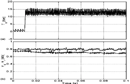
It turns out that the flux ripple is determined by
U
sd the direct component of the applied voltage vector. Fig.2 shows Classic DTC waveforms.Fig.2 Classic DTC (a) Torque response at 15 Nm (b) stator and rotor flux magnitudes
III. SPACE VECTOR MODULATION
Common disadvantages of conventional DTC are high torque ripple and slow transient response to the step changes in torque during start-up. Several techniques have been developed to improve the torque performance. One of them is to reduce the ripples is based on RIGHT ALIGNED SVM technique [11].SVM was first presented by a group of German researched in the second half of the 1980s. Since then, a lot of work has-been done on the theory and implementation of SVM techniques. SVM techniques have several advantages that a reoffering better DC bus utilization, lower torque ripple, lower Total Harmonic Distortion (THD) in the AC motor current, lower switching losses, and easier to implement in the digital systems. At each cycle period, a preview technique is used to obtain the voltage space vector required to exactly compensate the flux and torque errors. The torque ripple for this SVMDTCis significantly improved
and switching frequency is maintained constant [11]. SVM, based on the switching
Between two adjacent boundaries active vectors and a zero vector during one switching period, Tz, and for a given Reference voltage vector in the first sector (0-60o) is shown in Figure
RIGHT ALIGNED SVM in the first sector (a) reference voltage vector (b) Switching pattern for three-phase modulation.
The switching times can be calculated using the following Equations
The reference vector V*s, a constant magnitude and frequency in the steady-state, is sampled at equal time intervals of Tz. Within this sample time, the inverter is switched and made to remain at different switching states for different durations of time such that the average space vector generated within sample period is equal to the sampled value of the reference vector, both in terms of magnitude and angle[12, 13].The switching states that can be used within Tz are the two zero states and the active states which are SA and SB, with vectors V1 and V2 respectively forming the start and the end boundaries of the sector as shown in Figure 4. The two switching states (SA and SB) are named active switching states. SA indicates the inverter switching states (001), (100), or (010)and SB indicates the inverter switching states (101), (110) or(011). Active vector times, TA and TB, are defined as the times due to the active switching states, SA and SB respectively. Null vector times T0 and T7 are defined as the times due to the null switching states S0, (000), and S7, (111) respectively. In DTC,with the space vector PWM technique, the DTC transient performance and robustness are preserved and the steady state torque ripple is reduced. Moreover, the inverter switching frequency is constant and totally controllable [14]..
IV. VARIABLE-STRUCTURE DTC A. Operating Principles
. In the stator flux reference frame, the developed torque is
1
.
5
( )
9
sd s
e
p
i
T
=
Ψ
From (7) and (9), the developed torque is
(
)
( )
10 5
. 1
s
s s sq s e
R U p
Volume 3 – No.1, June 2010
35 It is now evident that the quadrature voltage
U
sq is qualified tocontrol the torque, under adequate decoupling. The flux control is based on (8).Torque control is based on (10).
B. Linear and Variable Structure Control
The linear and variable structure DTC (LVSC) block diagram is shown in Fig. 3. The controller employs a switching component and a linear one, and has dual behavior. This is a flexible DTC scheme that takes advantage of the best features of linear control, smooth operation, and of VSC, robustness to perturbations. An SVM unit,
which generates the VSI switching signals,
c b
a S and S
S , is
the output stage.
The sliding surface
S
=
S
Ψs+
jS
Te is selected as
( )
11
dt
de
c
e
S
ss s s
Ψ Ψ Ψ
Ψ
=
+
( )
12
dt
de
c
e
S
Te [image:3.612.321.513.48.288.2]Te Te Te
=
+
Fig.3 Linear and variable structure control scheme
Where
e
s s s∧
Ψ
=
Ψ
−
Ψ
*
and
e
TeT
eT
e∧
−
=
*are the flux and torque errors, “ * ” denotes reference quantities and “ ^ ” denotes
estimated quantities. Design constants
C
Ψs andC
Te are selected so as to impose the desired dynamics in the sliding mode.The control law that produces the reference voltage vector
∗ ∗
∗
=
+
sq sd
s
U
jU
U
in the stator flux reference frame isWhere s is the Laplace operator,
K
PΨ,K
IΨ ,K
PT ,K
IT are the PI controller gains, andK
VSCΨ ,K
VSCT are the VSC gains. Adequate balance, between the linear (proportional–integral (PI) specific) behavior and the switching (VSC specific) behavior, can be achieved by proper gains selection. In the transients, the linear component is dominant, and the PI gains are selected so as the linear control realizes the desired dynamic response
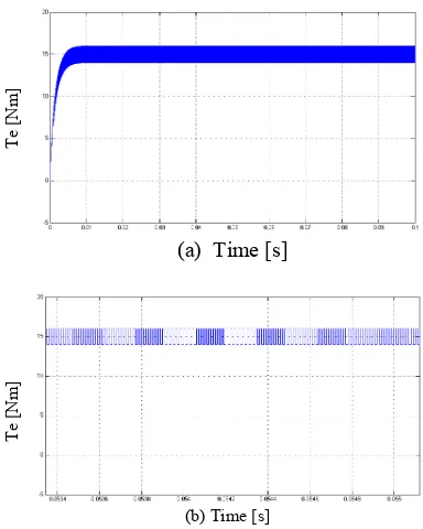
(a) Time [s]
(b) Time [s]
Fig.4 LVSC (a) Torque response at 15 Nm (b) Time zoom
Assuming accurate state estimation and ideal VSI (
U
s=
U
∗s), from (10) and (14), the torque dynamics result as(
1)
(
sgn( ))
(15)) (
Te VSCT e IT T PT T
IT PT T
e T K S
K K s K K
K s K K
T +
+ +
+
= ∗
Where
K
T=
3
p
Ψ
s/
2
R
s, andΨ
s
was assumed constant. The PI dynamics has been added in order to ensure zero steady-state torque error. This is an advantage with respect to classic DTC that works with nonzero torque error. A simulation result of LVSC is shown in fig.4. The transient response of LVSC scheme is 2.5 ms and which produces torque ripple ± 1 Nm and also has smooth transient response.C. Linear Feedback with Switched Gains Control
The second VSC-DTC strategy proposed is the linear feedback with switched gains DTC (LFSG). The block diagram is shown in Fig. 5. This scheme attempts to realize a typical behavior which is the opposite of that of the LVSC, i.e., quasi-linear operation in the steady state, and bang-bang operation during transients. This is a linear controller, whose gains are commutated according to a switching law
based on the control error. The sliding surface
S
=
S
Ψs+
jS
Te is selected the same as for LVSC (11) and (12). In the sliding mode, the system’s behavior is exclusively governed by S=0 . It follows that design constants and are to be selected so as to impose the desired first-order dynamic in the sliding mode.The control law that produces the reference voltage vector
∗ ∗
∗
=
+
sq sd
s
U
jU
U
in the stator flux reference frame is(
sgn( )) ( )
13*
s vsc
s I
P
sd e K S
s K K
U Ψ Ψ Ψ + Ψ Ψ
+
=
(
sgn( ))
( )
14*
s s Te vscT Te IT PT
sq e K S
s K K U
∧ Ψ ∧
Ψ + +
+
= ω
T
e
[N
m]
T
e
[N
[image:3.612.47.296.206.387.2]Volume 3 – No.1, June 2010
[image:4.612.47.292.54.261.2]36 Fig 5 Linear feedback with switched gain control scheme
where,
K
PΨ,K
IΨ ,K
PT ,K
IT are controller gains. These gains are to be selected so that the operation is fast and stable.Assuming accurate state estimation and ideal VSI (
U
s=
U
∗s), from (10) and (17), the torque transfer function results as(
sgn(
)
)
( )
(
18
)
)
(
∗+
+
+
=
eIT T PT T Te Te
IT PT T
e
T
K
K
s
K
K
S
e
K
s
K
K
T
Where
K
T=
3
p
Ψ
s/
2
R
s , andΨ
sis assumed constant. The discontinuous function affects the time constant of (18), and switching behavior will be dominant during transients. The steady-state operation will be quasi-linear.
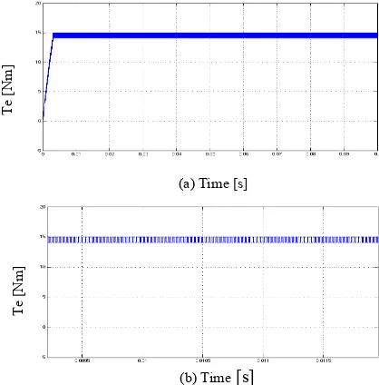
(b) Time [s]
Fig.6 LFSG (a) Torque response at 15 Nm (b) Time zoom
A simulation result of LFSG is shown in fig.6. The transient response of LFSG scheme is 1 ms and which produces torque ripple ± 0.5 Nm but the initial transients of torque is high.
D. Relays With Constant Gains Control
The last strategy is relays with constant gains DTC (RCG), shown in Fig. 7. This scheme contains only a variable structure controller and is a simplified version of LVSC. It displays VSC behavior during both transients and the steady-state operation. The sliding surface
Te s
jS
S
[image:4.612.318.534.57.158.2]S
=
Ψ+
is selected the same as for LVSC, (11) and (12). In sliding mode, the system’s behavior is governed by S=0, and design constants and are to be selected in the same way as for LVSC.Fig.7 Relays with constant gains control scheme
The control law that produces the reference voltage vector
∗ ∗
∗
=
+
sq sd
s
U
jU
U
in the stator flux reference frame iswhere,
K
PΨ,K
IΨ ,K
PT andK
IT are controller gains..Assuming accurate state estimation and ideal VSI (
U
s=
U
∗s), from (10) and (20), the torque results as
Te
=
K
T(
K
PTsgn(
S
Te)
+
K
ITv
)
(
21
)
Where
K
T=
3
p
Ψ
s/
2
R
s, v and is the integral ofdiscontinuous term
sgn(
S
Te)
. It represents the average ofsgn(
S
Te)
. The torque has two components: a switching one controlled byK
PT , and a linear slow motion, controlled byIT
K
. A largeK
PT speeds up the torque response, but increasesthe ripple in the steady state. A large makes the linear component dominant. Adequate balance between the linear and the switching components has to be found by proper gains selection. In this case the system has switching behavior in all situations, transients and steady state operation. simulation result of RCG is shown in fig.8. The transient response of RCG scheme is 4 ms and which produces torque ripple ± 0.7, Nm but has slower transient response
(b) Time [s]
Fig.8 RCG (a) Torque response at 15 Nm (b) Time zoom
(
sgn( ))
( )
16 *s s s
I P
sd e e S
s K K
U Ψ Ψ Ψ Ψ Ψ
+
=
(a
)
T
e
[N
m]
T
e
[N
m]
(
sgn( ))
( )
17*
s s Te Te Te IT PT
sq e e S
s K K U
∧ Ψ ∧
Ψ +
+
=
ω
(
sgn( ))
( )
19*
s I
P
sd S
s K K
U Ψ Ψ Ψ
+
=
T
e
[N
m]
(a) Time [s]
T
e
[N
[image:4.612.55.262.384.580.2] [image:4.612.318.527.487.699.2]Volume 3 – No.1, June 2010
37 V. SIMULATION RESULTS
[image:5.612.350.529.60.199.2]Two Mat lab models were developed to examine the different control algorithm. One is used for the conventionality and the other for the modified variable-structure DTC. The parameters of the induction motor are shown in Table I
TABLE I. Parameters of the induction motor used
d-q stator flux with conventional DTC scheme
d-q stator flux variable-structure direct torque controllers (VSDTC)
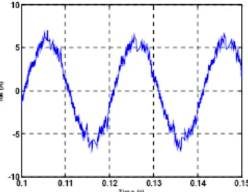
Stator d-current with conventional DTC scheme.
Stator d-current with RASVM-VSDTC scheme.
Output torque with conventional DTC scheme.
Volume 3 – No.1, June 2010
38 Stator flux magnitude with conventional DTC scheme.
VI. CONCLUSION
A family of variable-structure direct torque controllers for sensorless induction machine drives has been proposed. Simulation results of the proposed system have better behavior and more flexible control than classic DTC (torque ripple ± 2.5 Nm). The transient response of LVSC scheme is 2.5 ms and which produces torque ripple ± 1 Nm. The transient response of LFSG scheme is 1 ms and which produces torque ripple ± 0.5 Nm. The transient response of RCG scheme is 4 ms and which produces torque ripple ± 0.7 Nm. LFSG, followed by LVSC and RCG have the best overall behavior, far better than DTC. In classical DTC, as the torque ripple is maintained with in hysteresis band, switching frequency changes with speed. Moreover, the torque ripple is important problem at low speed. So using constant switching frequency a desired torque ripple can be achieved at low speeds where it really matters. The torque ripple for this SVM-DTC is significantly improved and switching frequency is maintained constant. Numerical simulations have been carried out showing the advantages of the SVM-DTC method with respect to the conventional DTC.
REFERENCES
[1] I. Takahashi and T. Noguchi, “A new quick response and high efficiency control strategy of an induction motor,” in Conf. Rec. IEEE-IAS Annu. Meeting, 1985, pp. 495–502
[2] M. Depenbrock, “Direct self control for high dynamics performance of inverter feed a.c.machines,” ETZ Arch., vol. 7, no. 7, pp. 211– 218, 1985.
[3] I. Boldea and S. A. Nasar, “Torque vector control (TVC) - A class of fast and robust torque, speed and position digital controllers for electric drives,” in Conf. Rec. EMPS’88, vol.15, 1988, pp.135–148.
[4] D. Casadei, F. Profumo, G. Serra, and A. Tani, “FOC and DTC: Twoviable schemes for induction motors torque control,” IEEE Trans. PowerElectron., vol. 17, pp. 779– 787, Sept. 2002.
[5] P. Pohjalainen, P. Tiitinen, and J. Lalu, “The next generation motor control method—Direct torque control, DTC,” in Conf. Rec. EPE’94, 1994, pp.115–120.
[6] J.-K. Kang and S.-K. Sul, “New direct torque control of induction motor for minimum torque ripple and constant switching frequency,” IEEETrans. Ind. Applicat., vol. 35,pp. 1076–1082,
Sept./Oct. 1999.
[7]D. Casadei, G. Serra, and A. Tani, “Implementation of a direct torque control algorithm for induction motors based on discrete
space vector modulation,” IEEE Trans. Power Electron., vol. 15, pp. 769–777, July 2000.
[8] T. G. Habetler, F. Profumo, M. Pastorelli, and L. M.Tolbert, “Direct torque control of induction machine using space vector modulation,”IEEE Trans. Ind.Applicat., vol. 28, pp. 1045–1053,
Sept./Oct. 1992.
[9] B. H. Kenny and R. D. Lorenz, “Stator and rotor Flux based deadbeat direct torque control of induction machines,” in Conf. Rec. IEEE-IASM Annu. Meeting, vol. 1, 2001, pp. 133– 139.
[10] C. Lascu, I. Boldea, and F. Blaabjerg, “A modified direct torque control for induction motor sensorless drive,”IEEE Trans. Ind. Applicat., vol. 36, pp. 122–130, Jan./Feb. 2000.
[11] A. Mir, M. E. Elbuluk, and D. S. Zinger, “Fuzzy implementation of direct self control of induction motors,” IEEE Trans. Ind. Applicat. vol. 30, pp.729–735, May/June 1994.
[12] P. Z. Grabowski, M. P. Kazmierkowski, B. K.Bose, and F. Blaabjerg, “Aimple direct-torque neuro-fuzzy control of PWM- inverter-fed induction motor drive,” IEEE Trans. Ind. Electron., vol. 47, pp. 863–870, Aug. \ 2000.
[13] V. Utkin, J. Guldner, and J. Shi, Sliding Mode Control in Electromechanical Systems. Ne York: Taylor & Francis, 1999.