Design of Optimal L
1
Stable IIR Digital Filter using
Hybrid Optimization Algorithm
Ranjit Kaur
University College of Engineering, Punjabi University,
Patiala,India
Manjeet Singh Patterh
University College of Engineering, Punjabi University,
Patiala,India
J.S. Dhillon
Sant Longowal Institute of Engineering and Technology,
Longowal, India
ABSTRACT
A Hybrid optimization algorithm is applied for designing stable infinite impulse response (IIR) digital filter based on L1-approximation error criterion. The proposed Hybrid
method calculates the optimal filter coefficients by exploring and exploiting the search space locally as well globally. The filter designed based on L1-approximation error possesses flat
passbands and stopbands in comparison to that of least square design and the minimax approach. A comparison with other design techniques is made, demonstrating that the proposed hybrid approach can obtain better digital IIR filters than the existing Genetic Algorithm (GA) based methods.
Keywords
Digital IIR filters, Hybrid search algorithm, L1-approximation
error, Stability.
1.
INTRODUCTION
Infinite impulse response (IIR) digital filters offer improved selectivity, computational efficiency, and reduced system delay compared to finite impulse response (FIR) digital filters with comparable approximation accuracy. However, its design is more difficult than FIR digital filters because IIR digital filters have a rational transfer function. The design task of IIR digital filters is to approximate a given ideal frequency response by a stable IIR digital filter under some design criterion. The IIR filter design principally follows two techniques: transformation technique and optimization technique. To implement Optimization technique with some criteria various optimization methods have been applied where p-error, mean-square-error, and ripple magnitudes (tolerances) of both pass-band and stop-band are used to measure performance for the design of digital IIR filters. The optimization algorithm described by Fletcher and Powell [1] is used to minimize a square-error criterion in the frequency domain. The semi-definite programming relaxation technique [2] has been adopted to formulate the design problem of IIR filter in a convex form. However due to non-linear and multimodal nature of error surface of IIR filters, conventional gradient-based design may easily get stuck in the local minima of error surface. Therefore, researchers have developed design methods based on modern heuristics optimization algorithms such as genetic algorithms [3-8], ant colony optimization [9], Hybrid Taguchi genetic algorithm [10], etc. However the performance of genetic algorithm based methods is often compromised by their very slow convergence. In this paper hybrid optimization algorithm is proposed that randomly explores the search space for the best solution locally as well globally for the design of IIR filters. The values of the filter coefficients are optimized with the hybrid approach to achieve L1-norm error criterion.
The paper is organized as follows. Section 2 describes the IIR filter design problem statement. The underlying mechanism about the methodology of the hybrid algorithm for designing the optimal digital IIR filters is described in Section 3. In Section 4, the performance of the proposed hybrid method has been evaluated and achieved results are compared with the design results by Tang et al. [4] and Tsai and Chou [11] for the low-pass (LP), high-pass (HP), pass (BP), and band-stop (BS) filters. Finally, the conclusions and discussions are outlined in Section 5.
2.
FILTER DESIGN PROBLEM
A digital IIR filter design problem involves the determination of a set of filter coefficients which meet performance specifications such as pass-band width and corresponding gain, width of the stop-band and attenuation, band edge frequencies, and tolerable peak ripple in the pass band and stop-band.
The transfer function of IIR filter is stated as below:
N
k z
k qk M
k z
k pk z
H
1 1
0 )
( (1)
Digital filter design problem involves the determination of a set of filter coefficients, pkand qk . Regardless of the filter type, the structure of cascading type digital IIR filter is:
N
k e j
k s j e k s
j e k r j e k r M
i e j
i q
j e i p x
H
1 2
2 1
1
2 2 1
1 1
1 1
1 1 )
, (
(2)
where
, 2 , 1 ,..., 21 , 11 , 21 , 11 , 1 , 1 ,..., 11 , 11
[p q p M q M r r s s r N r N
x
] , 2 , 1 s N
s N and vector
x
denotes the filter coefficients of dimension V×1 with V = 2M + 4N + 1.The IIR filter is designed by optimizing the coefficients such that the approximation error function in L1-norm for
magnitude is to be minimized. The magnitude response is specified at K equally spaced discrete frequency points in pass-band and stop-band where e(x)denotes the absolute error in L1-norm of magnitude response and is defined as
given below:
K
i Hd i H i x
x e
0 ( ) ( , )
)
Desired magnitude response Hd(i) of IIR filter is given as: stopband i for passband i for i d H , 0 , 1 )
( (4)
Minimize f(x)e(x) (5) Subject to: the stability constraints
) ...., , 2 , 1 ( 0 1
1qi i M (5a) ) ...., , 2 , 1 ( 0 1
1qi i M (5b) ) ...., , 2 , 1 ( 0 2
1s k k N (5c) ) ...., , 2 , 1 ( 0 2 1
1s k s k k N (5d) ) ...., , 2 , 1 ( 0 2 1
1sk s k k N (5e) The design of causal recursive filters requires the inclusion of stability constraints. Therefore, the stability constraints given by Eq. (5a) to Eq. (5e) which are obtained by using the Jury method Error! Reference source not found. on the coefficients of the digital IIR filter in Eq. (2) are included in the optimization process.
3.
HYBRID APPROACH FOR THE
DESIGN OF IIR FILTER
A hybrid approach is used to describe a sequential examination of trial solutions. The process of going from a given point to the next improved point is called a „move‟. A move is termed a „success‟ if the objective improves; otherwise, it is a „failure‟. The hybrid method uses three types of moves. The first move is Random initialization. Random initialization has been framed to acquire best starting point. In random initialization the starting point is found with the help of random search. The starting point is determined by applying Global search then further the starting point is moved by applying local search to record the best starting point. The search process is started by initializing the variable
j i
x using Eq. (6) which is used to calculate objective function using Eq. (2).
) ..., , 2 , 1 ; ..., , 2 , 1 ( ) min max ( min NV j V i where i x i x i r i x j i x (6)
where riis a random generated number, V is number of variables, NV is the population size.
The concept of opposition-based learning has been applied to accelerate reinforcement learning and back-propagation learning in neural networks [13]. The main idea behind
opposition-based learning is the simultaneous consideration of an estimate and its corresponding opposite estimate (i.e., guess and opposite guess) in order to achieve a better approximation for the current candidate solution. The opposition based strategy is applied and starting point xijis further explored using Eq. (7) to record the best starting point.
) ..., , 2 , 1 ; ..., , 2 , 1 ( ) min max ( max 1 NV j V i where i x i x i r i x j i x (7)
Out of 2NV members, best NV members constitute pool to initiate the process. For the local best single, best member is selected.
The second move is exploratory move designed to acquire information concerning the working of the function. This move is performed in the neighbourhood of the current point systematically to find the best point around the current point. The third move is a pattern move with random acceleration factor. The pattern move uses the information collected in the exploratory move and realize the minimization of the function by moving in the direction of an established „pattern‟. A new point is calculated by leaping from current best point
c i
x along a direction connecting previous best point xioand is executed as given below
). ..., , 2 , 1 ( )
(xic xio where i NV c
i x n i
x (8)
η is accelerating factor and is a random number varying between 0.5 to 2.0. Special care has been taken while generating accelerating factor which has been made random. In case the pattern move does not move the solution into a better region, the pattern move is not accepted and the extent of the exploratory move is reduced. The process is continued in a looped manner till the minimum value of function is achieved.
4.
DESIGN EXAMPLES AND
COMPARISONS
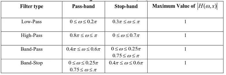
[image:2.595.103.495.641.772.2]For designing digital IIR filter 200 equally spaced points are set within the frequency domain [0,π] and for the purpose of comparison, the lowest order of the digital IIR filter is set exactly the same as that given by Tang et al. in [4] for the LP, HP, BP, and BS filters. Therefore, in this paper, the order of the digital IIR filter is a fixed number not a variable in the optimization process. The objective of designing the digital IIR filters is to minimize the objective function given by Eq. (5) with the stability constraints stated by Eq. (5a) to Eq. (5e) under the prescribed design conditions given in Table I.
Table 1. Prescribed Design Conditions for LP, HP, BP and BS Filters
Filter type Pass-band Stop-band Maximum Value of
H
(
,
x
)
Low-Pass 00.2 0.3 1
High-Pass 0.8 00.7 1
Band-Pass 0.40.6 00.25 75 . 0 1
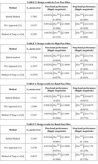
TABLE 2: Design results for Low Pass Filter Method L1-norm error
Pass-band performance (Ripple magnitude)
Stop-band performance (Ripple magnitude)
Hybrid Method 3.7903 0.9283 ( )1.0260
j e H (0. 0976)
1405 . 0 ) (ej H
(0.1405) TIA Approach [11] 3.8157 0.8914 ( )1.0000
j e
H
(0.1086)
1638 . 0 ) (ej H
(0.1638) Method of Tang et al.[4] 4.3395 0.8870 ( )1.009
j e
H
(0.1139)
1802 . 0 ) (ej H
[image:3.595.104.494.79.731.2](0.1802)
TABLE 3: Design results for High-Pass Filter Method L1-norm error
Pass-band performance (Ripple magnitude)
Stop-band performance (Ripple magnitude)
Hybrid method 3.9724 0.9625 ( )1.0265
j e H (0.0639)
1536 . 0 ) (ej H
(0.1536) TIA Approach [11] 4.1819 0.9229 ( )1.0000
j e H (0.0771)
1424 . 0 ) (ej H
(0.1424) Method of Tang et al.[4] 14.5078 0.9224 ( )1.003
j e H (0.0779)
1819 . 0 ) (ej H
(0.1819)
TABLE 4: Design results for Band-Pass Filter Method L1-norm error
Pass-band performance (Ripple magnitude)
Stop-band performance (Ripple magnitude)
Hybrid Method 1.3121 0.9825 ( ) 1.0249
j e H
(0.423)
0473 . 0 ) (ej H
(0.0473) TIA Approach [11] 1.5204 0.9681 ( )1.0000
j e H (0.0319)
0679 . 0 ) (ej H
(0.0679) Method of Tang et al.[4] 5.2165 0.8956 ( )1.000
j e H (0.1044)
1772 . 0 ) (ej H
(0.1772)
TABLE 5: Design results for Band-Stop Filter Method L1-norm error
Pass-band performance (Ripple magnitude)
Stop-band performance (Ripple magnitude)
Hybrid Method 3.3443 0.9334 ( )1.0041
j e H (0.0607)
1294 . 0 ) (ej H
(0. 1294)
TIA Approach [11] 3.4750 0.9259 ( )1.0000
j e H (0.0741)
1178 . 0 ) (ej H
(0.1278) Method of Tang et al.[4] 6.6072 0.8920 ( )1.000
j e H (0.1080)
1726 . 0 ) (ej H
0 0.1 0.2 0.3 0.4 0.5 0.6 0.7 0.8 0.9 1 0
0.2 0.4 0.6 0.8 1 1.2
M
a
g
n
it
u
d
e
Normalized Frequency
0 0.1 0.2 0.3 0.4 0.5 0.6 0.7 0.8 0.9 1
0 0.2 0.4 0.6 0.8 1 1.1
M
a
g
n
it
u
d
e
Normalized Frequency
0 0.1 0.2 0.3 0.4 0.5 0.6 0.7 0.8 0.9 1
0 0.2 0.4 0.6 0.8 1 1.1
Normalized Frequency
M
a
g
n
it
u
d
e
Hybrid Method
TIA Approach
[image:4.595.99.492.72.347.2]Method of Tang e.al.
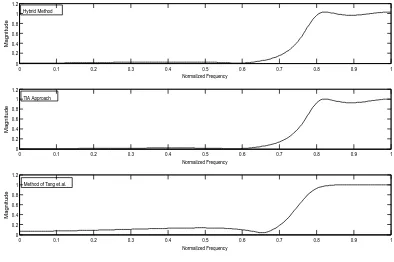
Figure 1: Frequency responses of low pass filter using the Hybrid approach and the method given in Error! Reference source not found. and [4] respectively.
0 0.1 0.2 0.3 0.4 0.5 0.6 0.7 0.8 0.9 1 0
0.2 0.4 0.6 0.8 1 1.2
Normailzed Frequency
M
a
g
n
it
u
d
e
0 0.1 0.2 0.3 0.4 0.5 0.6 0.7 0.8 0.9 1 0
0.2 0.4 0.6 0.8 1 1.2
Normailzed Frequency
M
a
g
n
it
u
d
e
0 0.1 0.2 0.3 0.4 0.5 0.6 0.7 0.8 0.9 1 0
0.2 0.4 0.6 0.8 1 1.2
Normailzed Frequency
M
a
g
n
it
u
d
e
Hybrid Method
TIA Approach
Method of Tang et.al.
[image:4.595.97.491.411.673.2]0 0.1 0.2 0.3 0.4 0.5 0.6 0.7 0.8 0.9 1 0
0.2 0.4 0.6 0.8 1 1.2
Normailzed Frequency
M
a
g
n
it
u
d
e
0 0.1 0.2 0.3 0.4 0.5 0.6 0.7 0.8 0.9 1
0 0.2 0.4 0.6 0.8 1 1.2
Normailzed Frequency
M
a
g
n
it
u
d
e
0 0.1 0.2 0.3 0.4 0.5 0.6 0.7 0.8 0.9 1
0 0.2 0.4 0.6 0.8 1 1.2
Normailzed Frequency
M
a
g
n
it
u
d
e
Hybrid Method
TIA Approach
[image:5.595.102.491.74.344.2]Method of Tang et.al.
Figure 3: Frequency responses of band pass filter using the Hybrid approach and the method given in Error! Reference source not found. and [4] respectively.
0 0.1 0.2 0.3 0.4 0.5 0.6 0.7 0.8 0.9 1
0 0.2 0.4 0.6 0.8 1 1.2
Normailzed Frequency
M
a
g
n
it
u
d
e
0 0.1 0.2 0.3 0.4 0.5 0.6 0.7 0.8 0.9 1
0 0.2 0.4 0.6 0.8 1 1.2
Normailzed Frequency
M
a
g
n
it
u
d
e
0 0.1 0.2 0.3 0.4 0.5 0.6 0.7 0.8 0.9 1
0 0.2 0.4 0.6 0.8 1 1.2
Normailzed Frequency
M
a
g
n
it
u
d
e
Hybrid Method
TIA Approach
Method of Tang et.al.
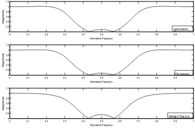
Figure 4: Frequency responses of band stop filter using the Hybrid approach and the method given in Error! Reference source not found. and [4] respectively.
From the evaluated results with the proposed hybrid method in Tables 2 to 5 and Figures 1 to 4, it can be seen that, for the LP, HP, BP, and BS filters, the proposed hybrid approach gives the smaller L1-norm approximation errors and the better
[image:5.595.97.492.407.667.2]5.
CONCLUSION
The paper proposes a hybrid optimization method for design of digital IIR filters based on L1-norm approximation error.
As shown through computational results, the proposed hybrid method works well with an arbitrary random initialization and it satisfies prescribed amplitude specifications consistently. On the basis of the results obtained, it can be concluded that the designed digital IIR filter in L1- sense possesses flat
passbands and stopbands responses as compared to methods purposed by Tsai and Chou [11] and Tang et al. [4]. The proposed approach for the design of digital IIR filers allows each filter, whether it is LP, HP, BP, or BS to be designed independently.
6.
REFERENCES
[1] R. Fletcher and M. J. D. Powell, “A rapidly convergent descent method for minimization,” Computer J., vol. 6, no. 2, pp. 163-168,1963.
[2] Aimin Jiang and Hon Keung Kwan, “Minimax design of IIR digital filters using SDP relaxation technique,” IEEE Transactions on Circuits and Systems-I, Vol. 57, No. 2, February 2010.
[3] J.H. Li and F.L. Yin, “Genetic optimization algorithm for designing IIR digital filters,” Journal of China Institute of Communications China, Vol. 17, pp. 1–7, 1996. [4] K.S. Tang, K.F. Man, S. Kwong and Z.F. Liu, “Design
and optimization of IIR filter structure using hierarchical genetic algorithms,” IEEE Transactions on Industrial Electronics, Vol. 45, No. 3, pp. 481–487, June 1998. [5] K. Uesaka and M. Kawamata, “Synthesis of
low-sensitivity second order digital filters using genetic programming with automatically defined functions,” IEEE Signal Processing Letters, Vol. 7, pp. 83–85, April 2000.
[6] G. Vanuytsel, P. Boets, L.V. Biesen and S. Temmerman, “Efficient hybrid optimization of fixed-point cascaded IIR filter coefficients,” Proceeding: IEEE International Conference on Instrumentation and Measurement Technology, Anchorage, AK, 2002, pp.793–797. [7] G.X. Zhang, W.D. Jin, and F. Jin, “Multi-criterion
satisfactory optimization method for designing IIR digital filters,” Proceeding: International Conference on Communication Technology, Beijing, China, 2003, pp. 1484–1490.
[8] Y. Liu, S.Q. Shao, H. Zhao, X.F. Liao, and J.B. Yu, “An application of genetic algorithms with guiding strategy in the design of digital filters,” Proceeding: International Conference on Communication, Circuits Systems, Chengdu, China, 2004, pp. 1141–1145.
[9] N. Karaboga, A. Kalinli, and D. Karaboga, “Designing IIR filters using ant colony optimisation algorithm,” Journal of Engineering Applications of Artificial Intelligence, Vol. 17, no. 3, pp. 301–309, April 2004. [10] J.-T. Tsai, J.-H. Chou, T.-K. Liu, “Optimal design of
digital IIR filters by using Hybrid Taguchi Genetic Algorithm,” IEEE Transactions on Industrial Electronics, Vol. 53,No. 3, pp. 867–879, June 2006.
[11] J.-T. Tsai and J.-H.Chou, “Optimal design of digital IIR filters by using an improved immune algorithm,” IEEE Transactions on Signal Processing, Vol. 54, No. 12, pp. 4582–4596,December 2006.
[12] I. Jury, Theory and Application of the Z-Transform Method. New York: Wiley, 1964.