Abstract
The fabrication and characterization of composite films of graphite/bioepoxy is disclosed. Thin films of ~0.1 mm thick are prepared using a simple solution mixing with mass proportion of 1/0.5 (biomonomer/Methylene Diphenyl Diisocyanate, MDI), upon differ treated graphite weight loading (5 wt.%, 10 wt.%, 15 wt.%, 20 wt.%, 25 wt.%, 30 wt.%) and drop casting at room temperature. The morphologic study by FE-SEM shows a homogeneously dispersed and strong interface between the graphite and the bioepoxy material. Ultraviolet-visible (UV-vis) spectrophotometer are performed to evaluate the changes in adsorption spectra arising with the increasing of graphite weight loading (wt.%) into the bio-based matrix. An eye opening I-V characteristic of the thin films where the percolation threshold occurs at higher graphite loading (20 wt.%, 25 wt.% and 30 wt.%) gives conductivity of 103-104 S/m. Whilst lower graphite loading (5 wt.%, 10 wt.% and 15 wt.%) somehow need further discussion. The influence of graphite in bioepoxy materials is paramount as it across insulating-semiconductor-conductor applications.
*Author for correspondence
Interconnected Interface Enhanced Electrical
Properties of Graphite in Bio-based Epoxy
from Insulating to Conductor Composites
Anika Zafiah M. Rus
1*, Nur Munirah Abdullah
1and M. F. L. Abdullah
21Sustainable Polymer Engineering, Advanced Manufacturing and Material Center (AMMC),
Faculty of Mechanical and Manufacturing Engineering, Universiti Tun Hussein Onn Malaysia, Parit Raja, Batu Pahat - 86400, Johor, Malaysia; [email protected], [email protected]
2Department of Communication Engineering, Faculty of Electrical and Electronic Engineering,
Universiti Tun Hussein Onn Malaysia, Parit Raja, Batu Pahat - 86400, Johor, Malaysia; [email protected]
1. Introduction
Bio-based epoxy materials exist with a very low quantity of free charge carriers, which make them as non-conductive and transparent to EM radiation. These disadvantages have resulted in the growth of research on electrically conductive biopolymers for electrical and electronic applications. Conductive polymers either inherently conductive (polyaniline)1.
They possess many merits over metallic conductors as such easy process ability to achieved conductivity, absorbing the specific radiation, improving thermal stability and foremost, reducing the cost. Numerous
Keywords: Bioepoxy, Graphite-Bioepoxy Composites, Insulating-Semiconductor-Conductor, Strong Interface
fillers can be reinforced into the insulating biopoly-mer matrix in order to achieve different conductivity ranges2-5. Graphite properties are quite remarkable:
high electrical conductivity, in spite of a low carrier concentration, high electrical anisotropy, high melting and boiling points. By its electronic structure, graphite is able to react either with compounds which give electrons to graphite (electron donors) or accept electrons from graphite (electron acceptors) and is recognized as the best conductive filler for its excellent conductive properties and well dispersion in polymer matrix6. In early work, Shih, et
higher stability compared with the composites using other carbon fillers as sensor7. Graphite/epoxy composites also
widely used as memory and energy storage8, plastic chip
electrode9, EM interference shielding etc. Therefore
in this work, treated graphite/bioepoxy composites are synthesized and characterized in order to determine the influence of varying treated graphite weight loading (wt.%) towards its morphological and optical properties in which contributes to electrical conductivity.
2. Methodology
2.1 Graphite Preparation
At room temperature ultrasonic solvent and flake graphite mixture were placed into a flask in the ultrasonic cleaning bath. After sonication, the graphite mixture is washed to neutrality with H2O, dehydrated, and dried in an oven for 60 min but below 60 °C. This method has been adopted from Jihui Li in 200710.
2.2 Biopolymer Preparation
Bioepoxy is prepared from renewable resources of Virgin Cooking Oil (VCO). VCO is obtained and chemically manipulated at laboratory scale using less than 1L tan of waste cooking oil11. The bioepoxy conversion begins with
the catalyst preparation to generate the epoxies from the unsaturated fatty compound and second reaction is the acid-catalyst ring opening of the epoxies to form polyols or bioepoxy12.
2.3 Composites Preparation
Free-standing films are prepared by mixing the bioepoxy with Methylene Diphenyl Diisocyanate (MDI) and acid treated graphite using mechanical stirrer and cast into square container which are then dried at ambient tem-perature for at least 6 hours. The resulting substrate films were peeled off and identified. Micrometer and optical microscope images are used to measure the thickness of the sample at particular point ranging ~0.1 mm.
2.4 Measurement and Characterization
In this research, the morphology of the composites is observed using an optical microscope instrument. UV-vis is used to determine the absorption or transmis-sion of UV-visible light (180 to 820 nm) for each sample. Measurements of current-voltage characteristics of the
prepared samples are carried out using Keithley 6517A electrometer. The resistances R are determined from the slopes of the current-voltage characteristics. Electrical resistivity ρ and conductivity σ are calculated from the expression ρ = σ –1 RLl/g, where l/g is the electrode geo-metrical factor (l is the total length of the electrode width and g is the electrode distance) L is the film thickness.
3. Results and Discussions
3.1 Morphological Study
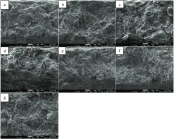
The morphology of graphite/bioepoxy composites appear promising as determined from FE-SEM images in Figure 1. The FE-SEM images appears a typical dis-order structures of treated graphite where randomly and homogeneously dispersed in bioepoxy matrix. The treated graphite is not a single graphite but rather consists of several layers or aggregation of graphite sheets. It is noted that the treated graphite contain functional groups such as -OH, -COOH after acid treatment which implies a strong interconnected interface between the bioepoxy and treated graphite. Hence, promote both physical and mechanical properties and it also enhanced the electron mobalized through the polymeric matrix composites in order to achieved the percolation threshold.
3.2 Optical Characterization
Figure 2 (a) shows the ultraviolet-visible spectra of graphite/bioepoxy composite with 5, 10, 15, 20, 25 and 30 wt.% of graphite loading respectively. The spectrum of each graphite/bioepoxy composite has an absorption peak in a range of 200–300 nm (graphene oxide has an absorption peak at 230 nm, 270 nm in graphene13. The
absorption peak at 230 nm is referred to π-π* transition of aromatic C-C ring while on the other hand, at 270 nm, is assigned to π-π* transition of C-O bonds now embedded using exfoliation and intercalation on the graphite. The graphite/bioepoxy shows increasing absorption spectra thus indicates lower the energy band vary to increasing graphite weight loading in which equivalent to previous research wherein polypropylene-graphite composites observe the same pattern14.
3.3 Electrical Characterization of the Film
(b) graphite-polyamide 6/polycarbonate (PA6/PC) composites15. This figure shows at the high weight
load-ing of graphite in the polymeric materials concurrently amplifies electrical contacts between the particles and as a result, the film resistivity decreases16. The graphs
[image:3.612.124.480.73.351.2]apparently shown that the calculated electrical con-ductivities from the reciprocal of the resistivity were increased by numerous orders of magnitude from 60-70 x 103 S/m upon 20, 25 and 30 wt.% of graphite/bioepoxy
[image:3.612.342.517.387.656.2]Figure 1. FESEM cross-sectional images upon 1000x magnification of graphite/bioepoxy composites (a) neat, (b) 5 wt.%, (c) 10 wt.%, (d) 15 wt.%, (e) 20 wt.%, (f) 25 wt.%, (g) 30 wt.%.
Figure 2. (a) UV-vis spectra of graphite/bioepoxy composite and (b) electrical conductivity (σ) with varying graphite weight percentage loading (wt. %).
Figure 3. The electrical conductivity (σ) of (a) graphite/ bioepoxy and graphite/epoxy, (b) graphite-polyamide 6/ polycarbonate (PA6/PC) composites15 as a function of
graphite weight loading (wt.%). (a)
[image:3.612.52.281.401.535.2]1047. Extending the gratitude to Microelectronics and Nanotechnology – Shamsuddin Research Center (MiNT-SRC), UTHM.
6. References
1. Balint R, Cassidy NJ, Cartmell SH. Conductive polymers: Towards a smart biomaterial for tissue engineering. Acta Biomaterialia. 2014 Jun; 10(6):2341–53.
2. Kalaitzidou K, Fukushima H, Drzal LT. A route for polymer nanocomposites with engineered electrical conductivity and percolation threshold. Materials. 2010;3(2):1089–103. 3. Yamamoto N, Guzman deVilloria R, Cebeci HG, Wardle BL.
Thermal and electrical transport in hybrid woven compos-ites reinforced with aligned carbon nanotubes. Proceedings of the 51st AIAA/ASME/ASCE/AHS/ASC Structures, Structural Dynamics and Materials Conference. 2010 Apr. 4. Li M, Wan Y, Gao Z, Xiong G, Wang X, Wan C, Luo H.
Preparation and properties of polyamide 6 thermal con-ductive composites reinforced with fibers. Materials and Design. 2013 Oct; 51: 257–61.
5. Stankovich S, Dikin DA, Dommett GHB, Kohlhaas KM, Zimney EJ, Stach EA, Piner RD, Nguyen SBT, Ruoff RS. Graphene-based composite materials.Nature. 2006 Jul 20; 442:282–6.
6. Narimissa E, Gupta RK, Choi HJ, Kao N, Jollands M. Morphological, mechanical and thermal characteriza-tion of biopolymer composites based on polylactide and nanographite platelets. Polymer Composites. 2012 Sep; 33(9):1505–15.
7. Shih WP, Tsao LC, Lee CW, Cheng MY, Chang CL, Yang YJ, Fan KC. Flexible temperature sensor array based on a graphite-polydimethylsiloxane composite. Sensors. 2010; 10(4):3597–610.
8. Zhou LM, Feng X, Mi XJ, Li YF, Xie HF, Yin XQ. Mechanical reinforcement and shape memory effect of graphite nano-platelet-reinforced epoxy composites. Journal of Intelligent Material Systems and Structures. 2014; 1–7.
9. Perween M, Parmar DB, Bhadu GR, Srivastava DN. Polymer-graphite composite: A versatile use and throw plastic chip electrode. Analyst. 2014 Nov 21; 139(22):5919–26.
10. Li JH, Li J, Li M. Preparation of expandable graphite with ultrasound irradiation. 2007 Nov; 61(28):5070–3.
11. Anika Zafiah MR. Polymer from renewable materials. Science Progress. 2010; 93(3):285–200.
composites, graphite/epoxy composites achieved 2-12 x 100 S/m upon 20, 25 and 30 wt.% while, 10-7-10-5 to
30-40 S/m of graphite–PA6/PC composites. Bare that slight differences in film thickness will jeopardize the film conductivity efficiency as thicker film will increase the resistivity.
Low electron mobility in the composites might be the cause for lower graphite loading (5, 10, 15 wt.%) in both bio-based epoxy and epoxy composites having a low magnitude (lower than 100 S/m) of conductivity, where
this characteristic cannot be justified by the graph. At this point, the graphite is covered by bioepoxy chains where the composite does not form a conductive inter-connected network in the insulating bioepoxy matrix to reach the percolation limit. Hence, techniques with dif-ferent measurement should be occupied such as surface conductivity, DC conductivity, thermally stimulated DC current in understanding the relationship between their electrical properties16.
4. Conclusion
Graphite-bioepoxy interaction has indicated a strong interconnected interface. Furthermore, the functional properties of the composite considerably rely on the conductive structure of graphite wherein randomly and homogenously dispersed in the bioepoxy matrix. Particularly, the values of the conductivity of the graph-ite/bioepoxy composite are 60-70 x 103 S/m upon 20
wt.%, 25 wt.%, and 30 wt.% of graphite loading . Whilst, lower graphite loading at 5 wt.%, 10 wt.% and 15 wt. % in bioepoxy composites need to employ under different measurement and further discussed. Overall, the mea-sured electrical properties gave a motivated considerable interest in the studies of graphite/bioepoxy compos-ite materials over insulating-semiconductor-conductor applications.
5. Acknowledgements
12. Anika Zafiah MR. Degradation studies of polyurethanes based on vegetables oils: Part I: Photodegradation. Progress in Reaction Kinetic and Mechanism. 2008; 33(4):391–63. 13. Thema FT,Moloto MJ, Dikio ED, Nyangiwe NN, Kotsedi
L, Maaza M, Khenfouch M. Synthesis and characterization of graphene thin films by chemical reduction of exfoli-ated and intercalexfoli-ated graphite oxide. Journal of Chemistry. 2013; 6.
14. Afroze S, Rahman MM, Kabir H, Md. Kabir A, Ahmed F, Md. Gafur A. Physical, optical and thermal properties
of graphite and talk filler reinforced Polypropylene (PP) composites. International Journal of Advanced Scientific and Technical Research. 2012 Oct; 5(2).
15. Roy N, Sengupta R, Bhowmick AK. Modifications of car bon for polymer composites and nanocomposites. Progress in Polymer Science. 2012 Jun; 37(6):781–819. 16. Bachari TS. Electric properties of Polyvinyl Acetate (PVA)