CONTROL
WAN HAMIDAH BINTI WAN ABAS
A project report submitted in partial fulfillment of the requirement for the award of the
Degree of Master of Electrical Engineering
Faculty of Electrical and Electronic Engineering Universiti Tun Hussein Onn Malaysia
ABSTRACT
In the field of fuzzy control theory, fuzzy logic controllers is one of the most active research areas and are particularly useful in controlling various types of physical processes. Therefore, this project also involved in usage of the fuzzy logic controller. Main objective of this project is to develop online position control of DC motor using Incremental Fuzzy Logic Controller (IFLC). The IFLC were developed by using MATLAB Simulink and implemented in the real position control system hardware. RAPCON platform is a hardware that was implemented in real-time session with DC motor. For simulation, signal generator used as the reference input in the form of square wave. The best gains used for the IFLC in simulation are: gain of error (GE) is 2.721, gain of change error (GCE) is 0.019 and gain of output (GCU) is 0.259. While real-time simulation use the most gains such as gain error (GE) of 1.785, gain of change error (GCE) is 0.0056955 and gain of output (GCU) is 0.01. Both method either simulation or real-time generate in 20 seconds. The result was obtained in form of graph and their performance was analysed. Based on the result, the IFLC shows the better performance of the overshoot percentage (%OS) of 0%.
ABSTRAK
CONTENTS
TITLE i
DECLARATION ii
DEDICATION iii
ACKNOWLEDGEMENT iv
ABSTRACT v
CONTENTS vii
LIST OF TABLES x
LIST OF FIGURES xii
LIST OF SYMBOLS AND ABBREVIATIONS xiv
CHAPTER 1 INTRODUCTION 1
1.1 Introduction 1
1.2 Problem Statement 2
1.3 Project Objectives 2
1.4 Project Scope 3
1.5 Project Outline 3
CHAPTER 2 LITERATURE REVIEW 4
2.1 Introduction 4
2.2 Previous Work 4
2.3 DC Motor Theory 6
2.4 Control Requirement 9
2.5 PID Controller 10
2.6 Incremental Fuzzy Logic 12
CHAPTER 3 METHODOLOGY 15
3.1 Introduction 15
3.2 Concept of The Project 17
3.3 Fuzzy Logic Controller Design 17
3.3.1 Mamdani Fuzzy Logic Control 19
3.3.2 Fuzzy Rule Base System 20
3.4 RAPCON Board 20
3.4.1 Specification 21
3.4.2 Hardware 22
3.4.3 Software 24
3.5 Hardware Connection 25
3.6 DC Motor With Encoder 25
CHAPTER 4 RESULT AND ANALYSIS 28
4.1 Introduction 28
4.2 DC Motor System Response 29
4.3 Incremental Fuzzy Controller Test 30
4.4 Incremental Fuzzy Controller with RAPCON 41 (Real-Time Experiment)
4.5 Discussion 51
CHAPTER 5 CONCLUSION AND RECOMMENDATION 52
REFERENCES 54
LIST OF TABLES
3.1 Rule Base for fuzzy controller 20
3.2 Specification of the RAPCON platform 21
3.3 Summary part of the RAPCON board functional block diagram
23
3.4 The DC motor parameters 26
4.1 IFLC controller parameter values 32
4.2 Reference input values setting 32
4.3 Specifications of parameter associated with response
at 360° 34
4.4 Specifications of parameter associated with response
at 330° 34
4.5 Specifications of parameter associated with response
at 300° 35
4.6 Specifications of parameter associated with response
at 270° 36
4.7 Specifications of parameter associated with response
at 240° 37
4.8 Specifications of parameter associated with response
at 210° 37
4.9 Specifications of parameter associated with response
at 180° 38
4.10 Specifications of parameter associated with response
at 150° 39
4.11 Specifications of parameter associated with response
at 120° 39
4.12 Specifications of parameter associated with response
4.13 Specifications of parameter associated with response
at 60° 41
4.14 IFLC controller parameter values 42
4.15 Reference input values setting 42
4.16 Specifications of parameter associated with response
at 360° 44
4.17 Specifications of parameter associated with response
at 330° 44
4.18 Specifications of parameter associated with response
at 300° 45
4.19 Specifications of parameter associated with response
at 270° 46
4.20 Specifications of parameter associated with response
at 240° 46
4.21 Specifications of parameter associated with response
at 210° 47
4.22 Specifications of parameter associated with response
at 180° 48
4.23 Specifications of parameter associated with response
at 150° 48
4.24 Specifications of parameter associated with response
at 120° 49
4.25 Specifications of parameter associated with response
at 90° 50
4.26 Specifications of parameter associated with response
LIST OF FIGURES
2.1 Crisp PD control system 5
2.2 Output and control signals for crisp PD control system
5
2.3 Separately excited DC motors 6
2.4 Response specification 9
2.5 General feedback control architecture 10
2.6 Functional diagram of a PID Control Loop 11
2.7 Incremental Fuzzy Controller 13
3.1 Flow chart for develop project 16
3.2 Block diagram of position control using IFLC system 17 3.3 Block diagram of fuzzy controller system 18
3.4 Fuzzy Inference System (FIS) 19
3.5 The Input and Output of variable 19
3.6 The functional block diagram of the RAPCON board 22
3.7 RAPCON Board (hardware) 24
3.8 RAPCON Software 24
3.9 Interfacing between Personal computer and DC Motor using RAPCON Board
25
3.10 DC motor with encoder 26
3.11 Block diagram of DC motor 27
4.1 Hardware connection 28
4.2 Open loop of DC motor diagram 29
4.3 Open loop of DC motor response 29
4.4 Close loop of DC motor diagram 30
4.5 Close loop of DC motor response 30
4.6 IFLC controller in subsystem form 31
4.8 Output response at 360 degree 33 4.9 Zooming of output response at 360 degree 33
4.10 Output response at 330 degree 34
4.11 Output response at 300 degree 35
4.12 Output response at 270 degree 35
4.13 Output response at 240 degree 36
4.14 Output response at 210 degree 37
4.15 Output response at 180 degree 38
4.16 Output response at 150 degree 38
4.17 Output response at 120 degree 39
4.18 Output response at 90 degree 40
4.19 Output response at 60 degree 40
4.20 Incremental Fuzzy Logic controller for DC motor system (real-time)
41
4.21 Output response based on IFLC at 360º 43
4.22 Zooming of output response based on IFLC at 360º 43
4.23 Output response based on IFLC at 330º 44
4.24 Output response based on IFLC at 300º 45
4.25 Output response based on IFLC at 270º 45
4.26 Output response based on IFLC at 240º 46
4.27 Output response based on IFLC at 210º 47
4.28 Output response based on IFLC at 180º 47
4.29 Output response based on IFLC at 150º 48
4.30 Output response based on IFLC at 120º 49
4.31 Output response based on IFLC at 90º 49
LIST OF SYMBOLS AND ABBREVIATIONS
DC - Direct Current
FIS - Fuzzy Interence System FLC - Fuzzy Logic Controller FPD - Fuzzy Proportional Derivative GCE - Gain of Change Error
GE - Gain Error
GCU - Gain of Output
IFLC - Incremental Fuzzy Logic Controller MATLAB - MATrix LABoratory
NN - Neural Network
OS - Overshoot
PD - Proportional-Derivative
PID - Proportional-Integral-Derivative
Tp - Peak Time
Tr - Rise Time
CHAPTER 1
INTRODUCTION
1.1 Introduction
DC motor has been widely used to improve the quality of human work, either
globally or individually such as in home appliances, industrial applications, robot manipulators etc. The DC motors are choosing because it has high reliabilities, flexibilities and low costs. Most of the applications of DC motor drivers are need a position control and speed.
There are many methods used as DC motor drivers such as PID, NN, Fuzzy Logic etc. Some applications may require using only one or two actions to provide the appropriate system control.
“Proportional-Integral-Derivative (PID) controllers are commonly used for motor control applications because of their simple structures and intuitionally comprehensible control algorithms” (Manafeddin Namazov and Onur Basturk, 2010). “The PID controller has been implemented in position control system, but still suffers from poor performance because of non-linear parameters. The PID does not give satisfactory results when control parameters, loading conditions and the motor itself are changed” (Mohammad Syah Rizal, 2013).
model of the system. Fuzzy logic is based on the principle of human expert decision making in problem solving mechanism (Dirman et. all, 2011).
By using the FLC, the position control performance will improve. This FLC develop will use Mamdani method. Mamdani method is widely accepted for capturing expert knowledge. Computer simulation is guided to illustrate the performance and show the result.
1.2 Problem Statements
Normally, the DC motor controller has a problem to achieve the desire position control. This problem among other is affected by the existing the nonlinearities component in the system. Moreover, these nonlinearities are often unknown and decrease the performance of position control. PID controller has been used because it most simple and easy to implement, but this type of controller still not able to improve the position control system performance because of the nonlinearities and uncertainties issues. The PID controller is not able to work well for non-linear system, and particularly complex and vague system that has no precise mathematical models. Some researchers used NN controller to improve the performance of position control, but it’s still not have a good performance. To overcome these problems, the Incremental Fuzzy Control System (IFLC) is developed in this project to ensure the DC motor as a position control driver is operable in any circumstance of situations.
1.3 Project Objectives
The major objective of this research is to use the incremental fuzzy logic control to develop online position control. Its measurable objectives are as follows:
1. To design the incremental fuzzy control system for position control with DC motor as a driver.
2. To implement an online position control based on incremental fuzzy control system.
1.4 Project Scopes
The scopes of this project are as follows:
a) MATLAB Simulink software is used to simulate the incremental fuzzy logic controller system developed.
b) The controller type is an Incremental Fuzzy Logic Control system. c) DC motor is as a driver of the position control.
d) The controller develop is an online.
e) Interfacing between personal computer (pc) where the controller is build and DC motor as a plant is done by RAPCON Board.
f) The type of layout is square wave.
1.5 Report Outline
This project deals with the proposed idea of develop a position control system for DC
motor by using an Incremental Fuzzy Logic Controller (IFLC). This report is divided
into five chapters. Chapter 1 is an introduction and gives an overview of the project and
speaks about the scope and the main objective. Chapter 2 discusses briefly about the DC
motor theory, PID controller and Incremental Fuzzy Logic Controller. Chapter 3
explained the method that was used in this project. Among the subtopics described are
flow chart for develop project, flow chart for the IFLC system, IFLC design, hardware
and software RAPCON, and concept of the project. Chapter 4 describes the MATLAB
Simulink model for IFLC system of position control. It also shows the result of
simulation and real-time experiment. And the last chapter is Chapter 5. This chapter is
CHAPTER 2
LITERATURE REVIEW
2.1 Introduction
This chapter will discuss the previous studies that have been accomplished by other researchers in same area. There are many researchers who have been implemented fuzzy logic control on the position control with DC motor as a driver. Related to this project title, the review focused on the incremental fuzzy control system resources like journal, proceeding thesis and also book.
2.2 Previous Works
There are many papers have been published about fuzzy control system design for DC motor (Manafeddin Namazov and Onur Basturk, 2010). The comparison between Proportional-Integral-Derivative (PID) and Fuzzy Logic Controller (FLC) application for position control has been done (Paul et.all.,1994) and the result shows the FLC performed better than PID. Other work, based on Neural Network controller. The results are obtained from the simulation and real-time experiment. From the result, neural network controller has been given the best controller for position control with DC motor as driver. The neural network controller satisfies all the specifications underlined better than PID controller. The neural network controller provides faster response and more precise control compared to PID controller (Muhamad Syah Rizal, 2013).
coefficient of PID controller is set to zero (i.e K = 0) (Manafeddin Namazov and Onur
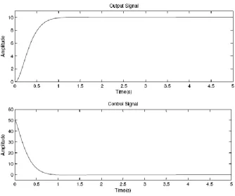
[image:16.595.118.522.132.257.2]Basturk, 2010).
Figure 2.1: Crisp PD control system
FLCs are complex, nonlinear controllers. Therefore it’s difficult to predict how
the rise time, settling time or steady state error is affected when controller parameters or
control rules are changed. On the contrary, PID controllers are simple, linear controllers
which consist of linear combinations of three signals (Manafeddin Namazov and Onur
Basturk, 2010).
[image:16.595.151.486.441.720.2]Figure 2.2 shows output and control signals of PD control system with adjusted parameters.
Ankur Gupta et.all. (2011) has been presented the position control of servo motor in three difference schemes. They are PID, Fuzzy and sliding mode Fuzzy Control. Each of them is discussed in term of the normal case, parameter variation case, and disturbance. The results show that PID is effective for a constant reference input but is ineffective for parameter variation and disturbance cases. Then Fuzzy controller gives better performance compared to PID controller but results are ineffective for disturbance case. While sliding mode fuzzy control shows that the system performance improvement when compared to PID and fuzzy control for parameter variation case and for disturbance case. So sliding mode fuzzy control is better in terms of control performance compared with other controllers.
2.3 DC Motor Theory
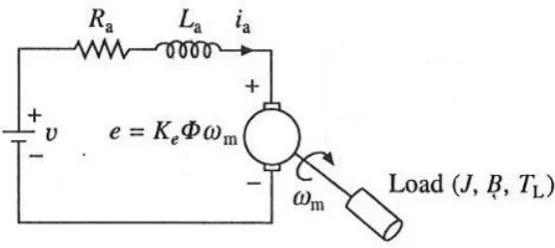
[image:17.595.177.455.500.624.2]In armature control of separately excited DC motors, the voltage applied to the armature of the motor is adjusted without changing the voltage applied to the field. Figure 2.3 describes a separately excited DC motor equivalent model (Norman S. Nise , 1995).
Figure 2.3: Separately excited DC motors
Where:
Kb ‐ Motor back emf constant (V/rad/sec) ia - Armature current (A)
Va - Armature voltage applied (V) Ra - Armature resistance (ohms) La - Armature inductance (mH)
2.3.1 Mathematical Equation
Voltage equation of the armature circuit under transient is given by
From the dynamics of motor load system
Further
When field current is kept constant, flux remains constant. Replacing Keф by a
constant Ke, yields
(2.3)
(2.4) (2.5) (2.6) (2.1)
2.3.2 Transfer Function
Laplace transforms of Eq. (2.1) to Eq. (2.5) are:
Substitute Eq. (2.9) into Eq. (2.6):
Then the relation between rotor shaft speed and applied armature voltage is represented by transfer function below:
The relation between position and speed is:
Then the transfers function between shaft position and armature voltage without load is:
(2.7) (2.8) (2.9)
(2.10)
(2.11)
(2.12) (2.13)
(2.14)
2.4 Control Requirement
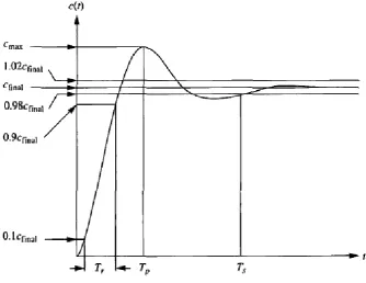
The controller requirements are analyzed based on its output response parameters. It will indicate the performance of the controller. The parameters are given below (Norman S. Nise , 1995).
[image:20.595.149.484.276.534.2]
Figure 2.4: Response specification
(i) Rise time, Tr
The time required for the response to progress from 0.1 to 0.9 of the final value.
(ii) Peak time, Tp
The time required to reach the first or maximum peak. (iii) Settling time, Ts
The time required for the response taken to fall within and stay within 2% of the steady-state value.
(iv) Percent overshoot, %OS
The maximum amount limits for the response to overshoots the steady-state, or final value at the peak time. The percentage overshoot is expressed as in Equation (2.16)
100
% max
final final c c c OS
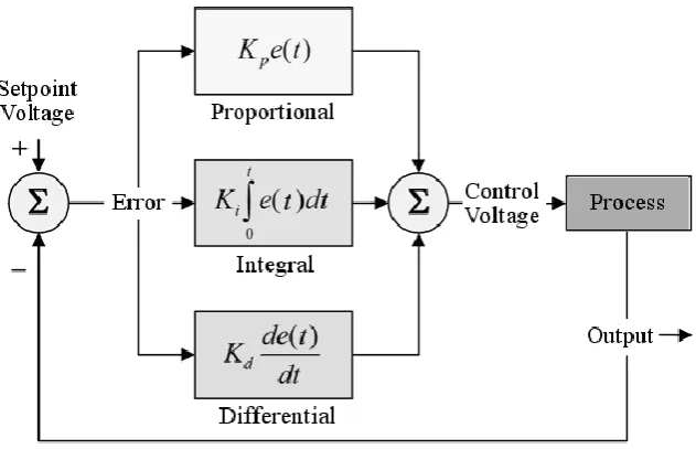
2.5 PID controller
PID stands for Proportional-Integral-Derivative. This is a type of feedback controller whose output, a control variable (CV), is generally based on the error between some user-defined set point (SP) and some measured process variable (PV). Each element of the PID controller refers to a particular action taken on the error.
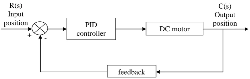
[image:21.595.116.516.557.684.2]There are many situations that require some type of position control system. This section reviews the fundamental of PID controllers and presents detailed simulations or design for development of digital servomotor controller. PID controllers are commonly used to regulate the time-domain behavior of many different types of dynamic plants. These controllers are extremely popular because they can usually provide good closed loop response characteristics, can be tuned using relatively simple rules and are easy to construct using either analogue or digital components. Consider the feedback system shown in Figure 2.5 where assume that the plan is a DC motor whose shaft position must be accurately regulated.
Figure 2.5: General feedback control architecture
(2.16)
+ -
PID
controller DC motor
The PID controller algorithm involves three separate constant parameters that is the proportional (P), the integral (I) and derivative (D) values. These values can be interpreted in terms of time where P depends on the present error, I on the accumulation of past errors, and D is a prediction of future errors, based on current rate of change. The weighted sum of these three actions is used to adjust the process via a control element such as the position of a control valve, a damper, or the power supplied to a heating element.
By tuning the three parameters in the PID controller algorithm, the controller can provide control action designed for specific process requirements. The response of the controller can be described in terms of the responsiveness of the controller to an error, the degree to which the controller overshoots the setpoint, and the degree of system oscillation. Note that the use of the PID algorithm for control does not guarantee optimal control of the system or system stability.
[image:22.595.164.480.494.697.2]Some applications may require using only one or two actions to provide the appropriate system control. This is achieved by setting the other parameters to zero. A PID controller will be called a PI, PD, P or I controller in the absence of the respective control actions. PI controllers are fairly common, since derivative action is sensitive to measurement noise, whereas the absence of an integral term may prevent the system from reaching its target value due to the control action.
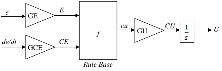
2.6 Incremental Fuzzy Logic
An incremental controller adds a change in control signal u to the current control signal,
Using Equation (below) with . The controller output is an increment to the current control signal.
Index n refers to the time instant. By tuning we shall mean the activity of adjusting the parameters , , and in order to achieve a good closed-loop performance.
The Incremental Fuzzy Logic Controller (IFLC) in Figure 2.7 is of almost the same configuration as the FPD controller except for the added integrator. The conclusion in the rule base is now called change in output (cu), and the gain on the output is accordingly GCU. The control signal U(n) at time instant n is the sum of all previous increments,
(2.17)
(2.18)
Figure 2.7: Incremental Fuzzy Controller
Notice again that this definition deviates from the historical fuzzy controllers, where the sampling period was left out. The function f is again the control surface of a PD rule base. The mapping is usually nonlinear, but with the usual favorable choice of design, Equation (2.20) is a linear approximation.
Insertion into Equation (2.19) yields the control action,
By comparing Equation (2.18) and (2.21) it is clear that the linear controller is a crisp PI controller ( ), and the gains are related as follows:
GE
GCE
GU f
e
de/dt
E
CE
cu CU U
Rule Base
(2.21) (2.20)
Note that the proportional gain now depends on . The gain is determined by the ratio between the two fuzzy input gains, and is the inverse of the derivative gain in FPD control; the gains GE and GCE change roles in FPD and IFLC controllers.
CHAPTER 3
METHODOLOGY
3.1 Introduction
The idea of this project is to develop an Incremental Fuzzy Logic Controller (IFLC) by using MATLAB Simulink and implemented in real position control system hardware. The main component of the position control in this case is a DC motor.
Figure 3.1 shows the development process of the overall project activities. The development of this project is divided into two parts: Part 1 and Part 2. Part 1 starts with studying and understanding the DC Motor theoretically especially its mathematic modeling. Other than that identify the controller method also can used to control the position of DC motor as a driver.
The platform for real time application applies is a RAPCON platform. The RAPCON platform consists of the hardware and software part. They are needed for real-time experimental position control develop. This platform is most suitable used as interface between DC motor and MATLAB Simulink for implement the real-time position control system.
3.2 Concept of the Project
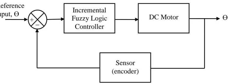
The concept to develop this project is as shown in Figure 3.2. The idea is to build a closed loop position control system of DC motor with encoder using Incremental Fuzzy Controller system. Before completing the process, the IFLC must be designed first. The membership function of IFLC was designed using Mamdani method. From the membership function, the IFLC rules are decided. This IFLC have two inputs that which position error (GE) and change of position error (GCE). The output of the IFLC is desired position.
[image:28.595.128.515.431.574.2]Block diagram in Figure 3.2 shows that the project was started with reference input enter into IFLC system that was treated using MATLAB Simulink. The treated IFLC will send the signal to DC motor to move to the desire the position. Then the actual position will be measured by the encoder as feedback signal to compare with reference input to generate the appropriate error signal as the input of IFLC controller to achieve the desired position. This process will be repeated for different angle to get desired position.
Figure 3.2: Block diagram of position control using IFLC system
3.3 Fuzzy Logic Controller Design
IFLC controller system is used to implement the position control with DC motor as a driver. The implementation of fuzzy logic controller requires the four key factors ((Mamdani, 1977) in Manafeddin, 2010). Figure 3.3 shows the block diagram of
Reference
input, Ɵ Incremental DC Motor Ɵ
Fuzzy Logic Controller _
+
Figure 3.3: Block diagram of fuzzy controller system
The block diagram of fuzzy logic controller system that shows in Figure 3.3 has four main parts. They are Fuzzification, Fuzzy inference, Defuzzification and Fuzzy rule base. The fuzzy logic controller for position control that developed in this project is designed with the following steps:
1. Design the membership function for fuzzy input and output variables. 2. Implement the fuzzy inference by a series of IF-THEN rules.
3. Inference engine derives a conclusion from the facts and rules contained in the knowledge base using various human expert techniques.
4. Process to map a fuzzy set into a crisp set. The defuzzification method use is the center of gravity (COG).
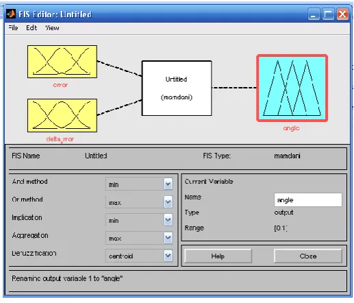
The fuzzy controller is implemented using MATLAB Fuzzy Logic Toolbox as shown in Figure 3.4. The fuzzy inference system (FIS) is used to edit and visualize used rules and membership functions. The resulting FIS model is then tested using the Simulink Toolbox, which also gives the convenience of building and analyzing dynamical systems graphically.
Fuzzification Fuzzy
Inference Defuzzification
Fuzzy Rule Base
Input Output
Figure 3.4: Fuzzy Inference System (FIS)
3.3.1 Mamdani Fuzzy Logic Control
In this project the Mamdani method as fuzzy inference technique is applied. Mamdani FIS has been chosen because its uses a technique of defuzzification of a fuzzy output. The IFLC is assumed has two inputs and one output. Input variables are error and change error, and the output variable is the DC motor input voltage.
Fuzzy Logic Rule (Mamdani)
Input Variables
Output Variables Error
Change Error
[image:30.595.116.539.523.719.2]3.3.2 Fuzzy Rule Base System
[image:31.595.255.384.257.369.2]The rule function of the Incremental Fuzzy Logic Controller was shown in Table 3.1. There are three fuzzy set for both input variables: Negative (N), Zero (Z) and Positive (P). For the output variable: Negative (N), Small Negative (Ns), Zero (Z), Small Positive (Ps) and Positive (P).
Table 3.1: Rule Base for fuzzy controller
θ Error (e) N Z P
C
ha
nge
err
or
(c
e) N N Ns Z Z Ns Z Ps P Z Ps P
The fuzzy logic rule-based are:
1. IF error is N and change error is N THEN output is N 2. IF error is N and change error is Z THEN output is Ns 3. IF error is N and change error is P THEN output is Z 4. IF error is Z and change error is N THEN output is Ns 5. IF error is Z and change error is Z THEN output is Z 6. IF error is Z and change error is P THEN output is Ps 7. IF error is P and change error is N THEN output is Z 8. IF error is P and change error is Z THEN output is Ps 9. IF error is P and change error is P THEN output is P
3.4 RAPCON Board
hardware. The board is interfaced to the host computer that runs MATLAB through a serial port.
[image:32.595.151.499.269.761.2]3.4.1 Specifications
[image:32.595.147.499.272.759.2]Table 3.2 shows the specification of the RAPCON platform.
Table 3.2: Specification of the RAPCON platform
Parts Specifications
Power Supply 6 – 15V, minimum 0.15A, regulated, (VPS is + and GND is – )
Interface 460800 baud, 8 bit data, no parity, 1 stop bit Analog inputs A0 – A7, 0 – 5V analog, 12 bit resolution Capture inputs C0 – C1, 0 – 5V digital, 16 bit resolution Digital inputs D0_d0 – D0_d7, 0 – 5V digital, 8 lines Pulse inputs K0 – K1, 0 − 5 V digital, 16 bit resolution General pulse inputs M0 – M1, 0 − 5 V digital, 16 bit resolution Encoder inputs E0 A, E0 B, E0 X – E1 A,E1 B, E1 X, 0 – 5V
digital, 16 bit resolution
Sensor inputs I0 – I1, 0 – 5 V digital, 16 bit resolution File inputs U0 − U7, internal, 16/64 bit resolution Frequency output F0 – F1, 0 – 5V digital, 16 bit resolution Analog outputs B0 – B1, 0 – 5V analog, 12 bit resolution Digital outputs G0_g0 – G0_g7, 0 – 5V digital, 8 lines Pulse outputs H0 – H1, 0 – 5V digital, 16 bit resolution General pulse
File outputs V0 − V7, internal, 16/64 bit resolution H-bridge power
outputs
P0 A, P0 B – P1 A, P1 B, 0 – (supply voltage)V digital,5A
Ground: GND, 0V
Sampling rate Up to 15.2kHz Voltage regulator
output VDD, 5 V, 0.25 A, regulated power supply
Size 10.16 cm × 7.62 cm
Weight 43.9 g
3.4.2 Hardware
[image:33.595.147.502.69.261.2]The real-time control board is based on a PIC30F2012 digital signal controller. The board is interfaced to the main computer that runs MATLAB through a serial port. The functional block diagram of the board is shown in the Figure 3.4.
Figure 3.6: The functional block diagram of the RAPCON board
[image:33.595.117.521.427.630.2]Table 3.3: Summary part of the RAPCON board functional block diagram.
The layout of the RAPCON board is shown in Figure 3.7. The inputs and outputs are connected to the board through standard pin header type connectors. The pins of all connectors are clearly indicated on the board for convenience. Access to the on-board 5V, 0.25A voltage regulator output is also provided for external light power supply requirements.
Part/Term Function
A0 – A7 Analog inputs B0 – B1 Analog outputs C0 – C1 Capture inputs D0_d0 – D0_d7 Digital inputs E0 – E1 Encoder inputs F0 – F1 Frequency outputs G0_g0 – G0_g7 Digital outputs H0 – H1 Pulse outputs
ADC Analog-to-digital converter DAC Digital-to-analog converter ICM Input capture module
OCM Output capture module
DIP Digital input port DOP Digital output port
QEM Quadrature-encoder module PWM Pulse-width modulator
FL Lowpass filters with outputs L0 – L1 HB H-bridges with outputs P0 – P1 µC Central microcontroller
UART Universal-asynchronous-receiver-transmitter unit
Figure 3.7: RAPCON Board (hardware)
3.4.3 Software
[image:35.595.199.441.543.726.2]REFERENCES
Aamir, Muhammad. (2013). On Replacing PID controller with ANN controller for DC motor position control. International Journal of Research Studies in Computing. pp. 21-29.
Ankur Gupta, Aziz Ahmad and Amit Kumar.(2011). Position Control Of Servo Motor Using Sliding Mode Fuzzy Controller. International Journal Of Advances In Engineering& Technology.pp. 118-127.
Brahoumi EM and Ben salah B. (2011). New Positioning Control of Stepper Motor using BP Neural Networks. Journal of Emerging Trends in Computing and Information Sciences. pp 300-306.
C. Ganesh, B. Abhi, V.P.Anand, S.Aravind, R.Nandhini and S.K. Patnaik. (2012). DC Position Control System – Dertermination Of Parameters and Significance on System Dynamics. ACEEE Int. J. On Electrical and Power Engineering. pp. 1-5.
C. S. Lee and R.V. Gonzalez. (2008). Fuzzy logic versus a PID controller for position control of a muscle-like actuated arm. Journal of Mechanical Science and Technology. pp 1475-1482.
D.F.Ahmed, S.K.H. Al Dawery and H.A.O Al-Anbari. (2007). On-Line Control Of The Nuetralization Process Based On Fuzzy Logic. Emirates Journal for Engineering Researh. pp.89-97.
Dirman Hanafi, Mohd Nor Mohd Than, Abdulrahman A.A. Emhemed, Tatang Mulyana, Amran Mohd Zaid, Ayob Hj. Johari. (2011). Heat Exchanger's Shell and Tube Modeling for Intelligent Control Design. IEEE. 978-1-61284-486-2/11/$26.00.pp.37-41
Gopal K. Dubey. Fundamental Of Electrical Drives second edition. Alpha Science International Ltd. pp.70-97.
Husain Ahmed, Dr. Gagan Singh, Vikash Bhardwaj, Saket Saurav and Shubham Agarwal. (2013). Controlling of DC Motor using Fuzzy Logic Controller. Conference on Advances in Communication and Control Systems 2013. pp. 666-670.
Jantzen, Jan. (2007). Foundations of Fuzzy Control. England: John Wiley & Sons Ltd.
K. Prema, N. Senthil Kumar and SubransuSekhar Dash. (2013). Online Control of DC Motors using Fuzzy logic Controller for Remote Operated Robots. J Electr Eng technol Vol.8. pp. 742-752.
Manafeddin Namazov and Onur Basturk. (2010). DC Motor Position Control Using Fuzzy Proportional-Derivative Controlles with different Defuzzification Methods. Turkish Journal Of Fuzzy Systems. pp.36-54.
Mohamad Syah Rizal Bin Abdullah, (2013) Neural Network Controller For Improvement Of Position Control System. Universiti Teknologi Tun Hussein Onn.
Mohd Fua’ad Rahmat and Mariam Md Ghazaly.(2006). Performance Comparison Between PID And Fuzzy Logic Controller In Position Control System Of DC Servomotor.Jurnal Teknologi.Universiti Teknology Malaysia. pp.1-17.
Norman S. Nise. (1995). Control System Engineering. 2nd. ed. Addison-Wesley Publishing Company, Canada. ISBN 0-8053-5424-7
Otman. M. Ahtiwash, Mohd Z. Abdulmuin and Siti Fatimah Siraj.(2002). A Neural-Fuzzy logic Approach for Modeling and Control of Nonlinear Systems. International Symposium on Intelligent Control. pp. 270-275.
Oyas Wahyunggoro and Nordin Saad.(2010). Development of Fuzzy-logic-based Self Tuning PI Controller for Servomotor. Advanced Stategies for Robot Manipulators. S. Ehsan Shafiei (Ed.), ISBN: 978-953-307-099-5. InTech, Available from: http://www.intechopen.com/books/advanced-strategies-for- robotmanipulators/development-of-fuzzy-logic-based-self-tuning-pi-controller-for-servomotor
Paul I-Hai Lin, Santai Hwang and John Chou. (1994). Comparison On Fuzzy Logic And PID Controls For A DC Motor Position Controller. Conference Record of the 1994 IEEE Industry Aplications Society Annual Meeting. pp 1930-1935. Pooya Hajebi and Seyed Mohammad Taghi AlModarresi. (2012). Online Adaptive
Fuzzy Logic Controller Using Neural Network for Networked Control Sytems. ICACT 2012. ISBN 978-5519-163-9. pp. 888-893.
Ritu Soni, DBV Singh, Pramod Pandey and Priyanka Sharma. (2013). Simulation of Optimal Speed Control for a DC Motor Using Conventional PID Controller and Fuzzy Logic Controller. International Journal of Information and Computation Technology. pp. 181-188.
The Math Work: Fuzzy Logic Toolbox for use with MATLAB.
U.A. Bakshi and V.U.Bakshi. (2011). Control System Engineering. Techical Publications, India. ISBN 978-81-8431-463-2.
Zeltom LLC. RAPCON: Real-time Rapid Control Prototyping Platform for Matlab/Simulink. Retrieved on December 26, 2013, from http://zeltom.com/products/rapcon