A Model Predictive Control to Reduce Torque Ripple for
Brushless DC Motor with Inbuilt Stator Current Control
M.Arun Noyal Doss
*, Subhransu Sekar Dash, D.Mahesh, V.Marthandan
Department of EEE, SRM University, Chennai *Corresponding Author: [email protected]
Copyright © 2013 Horizon Research Publishing All rights reserved.
Abstract
Torque-Ripple control of brushless DC motor has been the main obstacle in drive system in which speed fluctuation, vibration and acoustics noise should be minimized. This paper proposes the results of simulation and the experiment shows that the stator current can be improved and torque-ripple can be reduced obviously. Model predictive control (MPC) is used to generate the pulses to the gate circuit of three phase inverter. It consists of sensors, rectifier, controller .This has been simulated with the help of PSIM, filter effect is analyzed by FFT and current controlled technique is based on the generation of quasi-square wave currents using only one controller for all the three phases.Keywords
Brushless DC Motor (BLDC), Model Predictive Control(MPC) , PSIM, FFT, Stator Current, Torque Ripple1. Introduction
Brushless Direct current (BLDC) motors are rapidly gaining popularity. BLDC motors are used in industries such as appliances, automotive, aerospace, medical, industrial automation equipment and instrumentation. As the name implies, BLDC motors do not use brushes for commutation, instead they are electronically commutated. BLDC motors have many advantages over brushed DC motors like better speed versus torque characteristics high dynamic response, high efficiency ,high speed ranges, long operating life and noiseless operation.
In addition, the ratio of torque delivered to size of motor is higher. However their only drawback is that they need a commutator and brushes which are subject to wear and require maintenance which was implemented by solid-state switches The BLDC can be designed in various shapes of both stator and rotor .The increase in rotor poles will decrease the speed . Rotor can be designed in different shapes and size to reduce the cogging torque [10].It is the combination of a permanent excited synchronous motor and frequency inverter. The inverter has to replace the commutator of a conventional DC motor. Its armature winding corresponds to a three-phase winding in delta
connection. The commutator acts like a three-phase frequency converter .Stator (excitation) and rotor (armature) change places. The papers [3] and [4] tell us that the harmonics in d-q control signal which reduces the ripples by repetitive control and Fourier transform. A Brushless DC motor drive system with resonant pole inverter which was used to minimize the torque ripples has been analyzed in [5]. This paper [12] explains the minimization of the cogging torque with un-ideal emf of in BLDC motor .It also informs the the emf produced by BLDC is 120° trapezoidal wave.
The commutation of a brushless DC motor depends on position of rotor. The angle between magneto-motive force of stator and rotor is fixed to 90°(electrical) so the motor produces maximum torque and needs low reactive current it is useful for advance commutation by few degrees to (i)compensate the stray inductance effects and minimize reactive current. This has been discussed and implemented in [1].
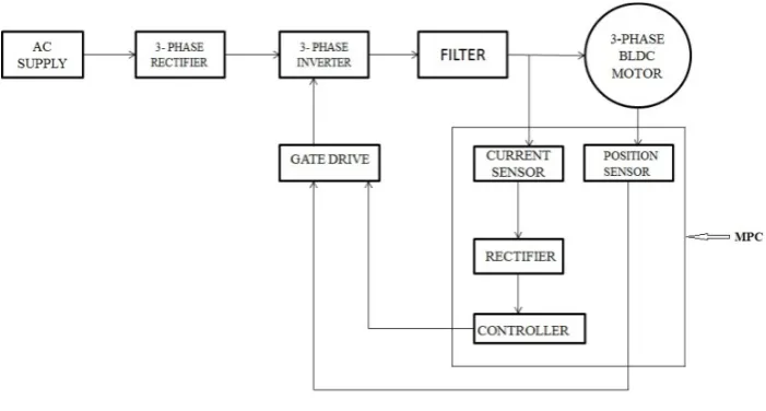
Model predictive control consists of current sensor, rectifier, controller and position sensor are discussed below. .
2. Current Controller Design
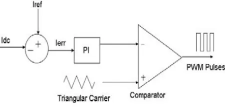
In current controller design PI controller is used. The main advantage of using PI controller is it has Zero steady error. The rotor shaft position is sensed by a Hall Effect sensor, a slotted optical disk or some other transducer, providing signals as represented. The signals are decoded by combinational logic to provide the firing signals for 120°conduction on each of the three phases [1].The commutation logic or rotor position decoder therefore has six outputs which control the upper and lower phase lag transistors. There will be level-shifting circuits to buffer the outputs of the logic circuit and provide the drive to the power devices.
not only reduces the current ripple but also avoids the need for wide bandwidth in the level-shifting circuit that feeds the upper phase leg transistors.
Figure 1. Current controller block
With higher DC supply voltages this can be a useful saving. Also current control of BLDC motor can be done by a constant DC signal [11]. The upper transistors need not be of the same type as the lower ones and need switch at the commutation and chopping signals to the lower transistors. Instantaneous current in the brushless PM motor is regulated in each phase by a hysteresis-type regulator which maintains the current within adjustable limits. This is called ‘current mode’ control and several algorithms are possible to control the switching. In this case sensors are needed in each phase and their bandwidth must be obviously wider than that of the sensing resistor. The speed feedback signal, derived from a Tacho-generator TG, can be derived from the shaft position sensor by a frequency-to voltage converter. In high performance systems that shaft position sensor may be a resolver or optical encoder, with special purpose decoding circuitry. At this level of control as a function of speed and load, to improve various aspects of performance such as efficiency, dynamic performance or speed range.
The functions inside the dotted line are all found on many products as well as many protective functions such as over and under voltage protection, over current protection and lockout protection(preventing the upper and lower switches in one phase leg from turning on at the same time and causing a ‘shoot-through’ failure).
3. Circuit Design
The drive system consists of a three-phase inverter, a BLDC permanent magnet motor, LC filter and a dc power supply. The inverter voltage for the motor is filtered by the filter circuit provided, which minimizes the high frequency switching voltage ripple component. The inductor- capacitor filter for the proposed work is connected in the interface of the drive and the motor. The LC filter in this system acts as a low pass filtering circuit which offer high impedance to high frequency component of the voltage and very minimum impedance to the power frequency voltage components and thereby minimizes harmonics in the supply voltage to the motor and the series inductance opposes the sudden changes in the current due to electronic commutation and thereby reduces the torque ripple. The reduction in torque ripple
techniques will be analyzed in detail [14].Also the implementation of fuzzy logic control in the reduction of commutation torque ripple in the Brush less DC motor will be studied [15]. This informs that Performance of the BLDC can enhanced over a wide range by MPC .
The sensing system is divided in two parts: Position Sensor System and Current Sensor System. The first system is based on three Hall Effect cells placed inside the motor, the second sensing system is based on the current sensors. The current sensors are to be placed in any two of the three phases of the motor. The measurement of the currents in the three phases is not required because of the following: 1) there is no neutral connection, and hence the third phase current can be obtained from the other two. 2) The sensing of the current is only required to get the value of the magnitude (the phase-shift and sequence is given by the position sensor).
Assuming only one current sensor, it could be possible to get information of the current during the cycle (2400).For
the other 1200, the PWM could be maintained with the same
duty cycle until the next information is obtained. Mainly PWM switching method is used for the minimizing the torque ripple in BLDC motor based on sensored rotor position control[13].The current waveforms of the PWM are smoother Hence, the output torque exhibits lower ripple contents. In general it is safer as it gives more accurate results to have at least two current sensors. Clearly, the information of one current sensor could be used, providing that the PWM is kept with constant duty cycle during the two intervals of 600. The utilization of single current sensor at the dc link is not possible since the power inverter was implemented using flat copper plates between transistors and electrolytic capacitors. This is one of the most common way of constructing power inverters because otherwise the leakage inductance between dc link and transistors becomes very large producing dangerous over voltages that could destroy power transistors.
The control circuit shown in fig 2 has sub blocks of analog and digital electronic circuits (comparators, PI controller and adder devices). As already mentioned the dc signal is obtained from signal rectification of the phase currents. This signal rectification uses germanium diodes to reduce the problem of nonlinearity introduced by the fixed voltage drop of the diodes used in the rectifier. However this problem becomes noticeable only when the current is smaller than 3% of the nominal value (120A), so it does not become a serious problem in the operation of the proposed method. The obtained current is compared with the reference and error signal Ierr is obtained. The error signal is processed using PI
.
Figure 2. Basic Block Diagram
4. Filter Design
[image:3.595.199.430.376.501.2]The selection of LC component present in the filter plays a major role in the performance of the drive. The charging and discharging of the capacitor improves the quality of the voltage given to the motor. This filter possesses the advantages of both L-filter and C-filter. In addition, ripple factor in L-C filter has lower value than obtained by either L-filter or C-filter for the same values of L and C.
Figure 3. Equivalent LC filter for one phase
Fig 3. shows the equivalent circuit of L-C filter for reducing the ripple from the output voltage. The inductor current rating should be equal to the current ratings of the motor.
The value of filter capacitor C can be calculated by
C = 10
2𝜔𝜔�𝑅𝑅2+(2𝜔𝜔𝐿𝐿𝐿𝐿)2
R is the load resistance and LL is the load inductance
The value of filter inductor L can be obtained by
VRF = √23 �(2𝜔𝜔)21𝐿𝐿𝐿𝐿 −1�
VRF is voltage ripple factor and according to IEEE standard maximum allowable range to ripples is up to 10%. So we are taking VRF as 0.01 and calculating L using C as already obtained.
Figure 4. Simulated Circuit diagram for the proposed method using PSIM
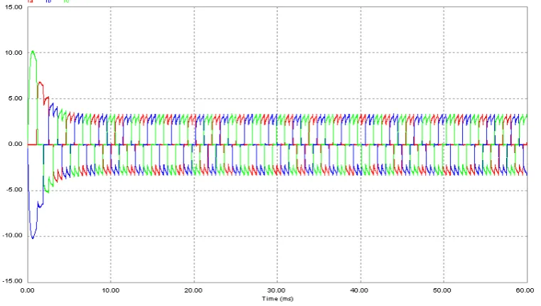
Figure 5. Three Phase current Waveforms
[image:4.595.93.517.550.723.2]Fig.4 shows the simulation circuit of proposed control technique and it is done using PSIM software. The output of the inverter is given to the BLDC motor via filters i.e LC filters. The motor currents are sensed and it is given to the rectifier and the obtained value is compared with the reference value and the error value is processed using PI controller. The obtained value is compared with the triangular wave to generate controlled PWM signals. The obtained pulses are taken from position sensor signals of the motor to give pulses to the three phase inverter. Fig.5 shows the three phase currents of the motor input.
(a)
[image:5.595.131.481.159.700.2](b)
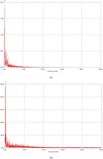
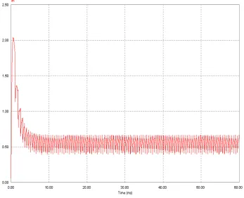
Figure 7. Current and Voltage analysis without Filters. (a) FFT spectrum of current in phase-A. (b) FFT spectrum of voltage in phase-A
(a)
[image:6.595.130.478.86.630.2](b)
Figure 8. Current and Voltage analysis with Filters. (a) FFT spectrum of current in phase-A. (b) FFT spectrum of voltage in phase-A
Simulation results for voltage and current for the motor with filter is presented and fig. 8 (a) shows the harmonic analysis of line current (Ia).
(a)
[image:7.595.128.481.82.694.2](b)
Figure 10. bRectified motor Current
6. Conclusion
In this paper the different control strategy for brushless dc motor is proposed. It is mainly based on generation of quasi square wave currents using only one current controller for the three phases instead of three current controllers. The salient features of this technique is it is very simple and all the phase currents are balanced and the important of all is current is controlled through a DC component so that phase over currents are eliminated. The ripple content in the voltage and current waveforms are observed with and without filter. Here it is observed torque ripples are reduced more when using filter, and we have used both current control technique to smoother current which have direct effect on the output torque of the motor and voltage ripples are reduced using the filters.
REFERENCES
[1] Yong Liu, Z. Q. Zhu, “Commutation-Torque-Ripple Minimization in Direct-Torque-Controlled PM Brushless DC Drives” IEEE trans.Industry Applications, Vol. 43, No. 4, August 2007. PP 1012- 1021.
[2] Zhi Yang Pan, and Fang Lin Luo, “Novel resonant pole inverter for Brushless DC motor drive system”, IEEE Trans on Power Electronics, Vol. 20, No. 1, Jan 2005. PP 173-181.
[3] J.S Kim, s. Doki and M.Ishida, “Improvement of IPMSM
sensorless control performance using Fourier Transform and repetitive control,” in proc.27th Annu. Conf. IEEE IECON, 2002. PP. 597-602.
[4] S. Harrori, M. Ishida, and T. Hori, “Vibration suspension control method for PMSM using repetitive control with auto tuning function and Fourier transform.” In Proc 27th Annu. Conf. IEEE IECON,2001, PP 1673-1679.
[5] Zhi Yang Pan, and Fang Lin Luo, “Novel resonant pole inverter for Brushless DC motor drive system”, IEEE Trans on Power Electronics, Vol. 20, No. 1, Jan 2005. PP 173-181. [6] Roque Alfredo Osornio-Rios, Rene de Jesus
Romero-Troncoso, Gilberto Herrera, and Rodrigo Castaneda- Miranda, “FPGA implementation of higher degree polynomial acceleration profiles for peak jerk reduction in servomotors.”, Robotics and Computer-Integrated Manufacturing (2008) Science Direct, Jan 2008.(doi:10.1016/j.rcim.2008.01.002)
[7] KayhanGulez, Ali Ahmed Adam, and HalitPastaci, ”Torque Ripple and EMI Noise Minimization in PMSM Using Active Filter Topology and Field-Oriented Control,” IEEE Trans. Industrial Electronics, Vol. 55, No. 1, pp. 251-256, Jan 2008.
[8] AlbertRajan, A. and S.Vasantharathna, 2009. Harmonics and torque ripple minimization using L-C filter for brushless DC motors. Int. J. Recent Trends Eng., 2: 239-248. http://ijrte.academypublisher.com/vol02/no05/ijrte02052392 43.pdf
[10] Hwang, K.Y., S.B. Rhee, B.Y. Yang and B. Kwon, 2007. Rotor pole design in spoke-type brushless DC motor by response surface method. IEEE Trans. Magn., 43: 1833-1836. DOI: 10.1109/TMAG.2007.892616
[11] Karthikeyan, J. and R. Dhanasekaran, 2010. Simulation and implementation of current control of BLDC motor based on a common dc signal. Int. J. Eng. Sci. Technol., 2: 1632-163.
[12] Lu, H., L. Zhang and W. Qu, 2008. A new torque control method for torque ripple minimization of BLDC motors with un-ideal back EMF. IEEE Trans. Power Electr., 23: 950-958. DOI: 10.1109/TPEL.2007.915667
[13] Salah, W.A., D. Khaleel and J. Hammadi, 2011. PWM
switching strategy for torque ripple minimization in BLDC motor. J. Electr. Eng., 62: 141-146. DOI: 10.2478/v10187-011-0023-1
[14] Varatharaju, V.M., B.L. Mathur and K. Udhayakumar, 2011. A comparative study with modeling and simulation of torque ripple reduction techniques in BLDC motor. Europ. J. Scientif. Res., 1450-216X: 295-305.