An investigation into the design and performance of an
automatic shape control system for a Sendzimir cold
rolling mill.
DUTTON, Kenneth.
Available from Sheffield Hallam University Research Archive (SHURA) at:
http://shura.shu.ac.uk/19587/
This document is the author deposited version. You are advised to consult the
publisher's version if you wish to cite from it.
Published version
DUTTON, Kenneth. (1983). An investigation into the design and performance of an
automatic shape control system for a Sendzimir cold rolling mill. Doctoral, Sheffield
Hallam University (United Kingdom)..
Copyright and re-use policy
795062301 TELEPEN
S heffield city Polytechnic Library
ProQuest Number: 10694468
All rights reserved
INFORMATION TO ALL USERS
The quality of this reproduction is dependent upon the quality of the copy submitted.
In the unlikely event that the author did not send a com plete manuscript and there are missing pages, these will be noted. Also, if material had to be removed,
a note will indicate the deletion.
uest
ProQuest 10694468
Published by ProQuest LLC(2017). Copyright of the Dissertation is held by the Author.
All rights reserved.
This work is protected against unauthorized copying under Title 17, United States C ode Microform Edition © ProQuest LLC.
ProQuest LLC.
789 East Eisenhower Parkway P.O. Box 1346
AN INVESTIGATION INTO THE DESIGN AND PERFORMANCE OF AN
AUTOMATIC SHAPE CONTROL SYSTEM FOR A SENDZIMIR COLD ROLLING MILL
Kenneth Dutton, B.Sc.,C.Eng., M.I.E.E.
May 1983
A thesis submitted in line with the
requirements of the CNAA, as partial fulfilment of the conditions necessary for the award of the Ph.D. (Doctor of
Philosophy) Degree.
Department of Electrical & Electronic Engineeering, Sheffield City Polytechnic,
Pond St.,
Sheffield, SI 1WB.
Collaborating Establishment:
British Steel Corporation,
Sheffield Laboratories, Moorgate,
To Lizzie my wife and Suzie my daughter
(with many thanks for your patience during my prolonged
absences from normal family life, and also with the hope that outstanding tasks around the house may now stand a
Declaration
Whilst registered for this degree I have not been a registered candidate for any other academic award. None of the material in this thesis has been used in any other
submission for an academic award.
All sources of information are acknowledged and duly referenced.
Ken Dutton
Request for Confidentiality
As the subject of this research is now being installed as a working scheme by the author at a British Steel Works it is requested that this thesis be allowed to remain
ACKNOWLED GEMENTS
During the course of this work discussions have clearly taken place with many different people, as a result of
which much helpful comment has been forthcoming. I heartily thank anyone to whom this applies.
Special thanks are due to my supervisors for their guidance and encouragement, namely to Professor M. J. Grimble of Strathclyde University (formerly of
Sheffield City Polytechnic)1 and Dr. K. A. Jukes of Bristol Polytechnic (formerly also of Sheffield City Polytechnic). Thanks also to Mr. M» A. Foster of
British Aluminium (who was formerly my industrial second supervisor whilst he was employed at BSC Sheffield Labs.) and to Dr. G. F. Raggett of Sheffield City Polytechnic.
I am also grateful to all friends and colleagues at BSC Sheffield Laboratories and BSC Stainless, Shepcote Lane, Sheffield, who have been involved with this work, and to Dr. J. F. Barrett of Strathclyde University for his useful ideas and comments.
Many thanks also to Mrs. J. Harper for typing the manuscript.
Papers Published
Dutton K. , "Shapemeters and Shape Control Systems: Survey of Literature”, BSC internal Research Report
SH/IC/8216/-/78/A, 1978, (Drafted 1976).
Dutton K. , ’’Description of the Operation of Sendzimir Mill Eccentric Actuators” , BSC internal Technical Note MC/CA/8216/-/79, 1979.
Dutton K. , ’’The Development of a Mathematical Model
Describing the operation of Sendzimir Mill Eccentric
Actuators” , BSC internal Technical Note MC/CA/8216/1/79» 1979*
Dutton K. , ’’Mathematical Definition of Sendzimir Mill Cluster Geometry and Roll Force Distribution", BSC internal
Technical Note MC/CA/8216/2/79, 1979.
Dutton K . , ”A Mathematical Model for Prediction of Sendzimir Mill Workroll Profile and Strip Shape", BSC internal Technical Note MC/CA/8216/3/8 1, 1981.
Dutton K . , Barrett J.F. and Grimble M.J., "The Shape Control Problem for a Sendzimir Cold Steel Rolling Mill",
Proc. Symposium on Application of Multivariable Systems Theory, Plymouth, 1982.
Harrison R.S.T., Walton A.B. and Dutton K . , "Data Logger of Strip Shape for Number 5 Sendzimir Mill, Shepcote Lane," BSC internal Technical Note TS/MC3/8216/3/82/A, 1982.
Dutton K . , "Overview of the Development of an Automatic
Shape Control System for a Sendzimir Cold Steel Rolling Mill", Submitted for presentation at the IEE Colloquium
An Investigation into the Design and Performance of an Automatic Shape Control System for a Sendzimir
Cold Rolling Mill Ken Dutton
SYNOPSIS
Shape Cor flatness) control for rolled steel strip is becoming increasingly important as customer requirements become more stringent. Automatic shape control is now more or less mandatory on all new four-high cold mills, but no comprehensive scheme yet exists on a Sendzimir mill. This is due to the complexity of the control system design on such a mill, where many more degrees of freedom for control exist than is the case with the four-high mills.
The objective of the current work is to develop, from first principles, such a system; including automatic
control of the As-U-Roll and first intermediate roll actuators in response to the measured strip shape. This thesis concerns itself primarily with the As-U-Roll control system.
The material presented is extremely wide-ranging. Areas covered include the development of original static and
dynamic mathematical models of the mill systems, and test ing of the plant by data-logging to tune these models. A basic control system philosophy proposed by other workers is modified and developed to suit the practical system requirements and the data provided by the models. The control strategy is tested by comprehensive multivariable simulation studies. Finally, details are given of the practical problems faced when installing the system on the plant. These include problems of manual control inter-action bumpless transfer and integral desaturation.
At the time of presentation of the thesis, system commissioning is still in progress and production results are therefore not yet available. Nevertheless, the
CONTENTS
CHAPTER 1. INTRODUCTION
1.1 Background to the Shape Control Problem 1 1.2 Means of Shape Control in Four-High Stands 9 1.3 Description of the Present Project and
Thesis 11
CHAPTER 2. PHYSICAL DESCRIPTION OF THE SENDZIMIR MILL INSTALLATION
2.1 Introduction 13
2.2 Mechanical Description of the Sendzimir Stand 14 2.3 Mechanical Description of the Mill's
Control Actuators 18
2.3.1 Push-Up System Operation 20 2.3.2 Side Eccentrics Operation 22 2.3.3 Screwdown System Operation for Gauge
Control 3
2.3.4 As-U-Roll Operation for Shape Control 24 2.3.5 First Intermediate Rolls for Shape
Control 30
2.4 The ASEA Shapemeter System 33
2.4.1 Description of the Stressometer Roll 33 2.4.2 Description of the Signal Processing 34
CHAPTER 3. STATIC MATHEMATICAL MODEL OF THE MILL
3.1 Introduction and List of Principal Symbols 38 3.2 Modelling of the Control Actuators 46 3.3 Modelling of Roll Force Distribution in
the Cluster 69
3.4 Rolling Load and Roll Flattening Calculations 77 3.5 Philosophy of Roll Stack Deflection Model 85 3.6 Calculation of Loading Pattern on the Upper
Central Second Intermediate Roll 88 3.7 Upper Central Second Intermediate Roll
Deflection Calculation 101
Page N o . 3.9.2.2 Deflection due to a Force on 138
the RH end of the Roll
3.9.2.3 Deflection due to a Force over
the Strip 139
3.10 Calculation of Strip Shape 145 3.11 The Computer Model and the Mill Gain Matrix 155
3.12 Discussion of Results 160
CHAPTER 4. DYNAMIC MATHEMATICAL DESCRIPTION OF THEPLANT
4.1 Introduction 174
4.2 The As-U-Roll Actuators 174
4.3 First Intermediate Roll Lateral Adjustment
Actuators 180
4.4 Transfer of Strip Between Mill and Shapemeter 182
4.5 The Shapemeter System 184
CHAPTER 5. PLANT TESTING FOR MODEL VALIDATION
5.1 Introduction 186
5.2 Test Instrumentation and Set-Up 187
5.3 Static Model Validation 190
5.4 Dynamic Model Validation 196
5.4.1 The As-U-Roll Actuators 196 5.4.2 First Intermediate Roll Actuators 197 5.4.3 Transfer of Shape Between Mill and
Shapemeter (Including Shapemeter) 199 5.4.4 Closed-loop controlled As-U-Rolls 203 CHAPTER 6 CONTROL SYSTEM DESIGN
6.1 Introduction 207
6.2 Parameterization of Shape Measurements 207 6.3 Target Shape for the Control System 216
6.4 Control System Philosophy 222
6.5 Control System Design 224
CHAPTER 7 DYNAMIC SIMULATION STUDIES
7.1 Introduction 236
7.2 Description of the Simulation 237 7.3 Calculation of Initial States 241 7.4 Post-Initialization Operation of the
Simulation 244
CHAPTER 8 SYSTEM IMPLEMENTATION ON THE MILL
Page N o .
8.1 Introduction 266
8.2 Limiting of Relative Actuator Travel 266 8.3 Integral Desaturation in the Controller
& Bumpless Transfer 271
8.4 Computer Hardware 2 76
8.5 Plant Interfaces 277
8.6 Shapemeter Edge Rotor Compensation 282 8.7 System Interaction with First Intermediate
Roll Control 288
CHAPTER 9 CONCLUDING REMARKS 292
REFERENCES 301
APPENDICES
APPENDIX 1 HETENYI1S THEORY OF BEAMS ON ELASTIC PageNo. FOUNDATIONS
A 1 .1 Differential Equation of the elastic line A 1 . A1.2 Beams of Infinite Length A 1 .
A1.3 Beams of Finite Length A 1 .
A1.4 Summary of Procedure A 1 .
APPENDIX 2 CALCULATION OF FOUNDATION MODULUS A 2 . APPENDIX 3 BENDING THEORY FOR A CANTILEVER HAVING AN
ELASTICALLY SUPPORTED ROOT A3.
APPENDIX 4 EFFECTS OF NON-RIGHT-CYLINDRICAL ROLLS ON
BEAM THEORY A 4 .
A4.1 Roll Camber Definition A 4 .
A4.2 Incorporation in the Theory A 4 . A4.3 Tapered First Intermediate Rolls A 4 .
APPENDIX 5 EXAMPLES OF MATRICES GENERATED A 5 . A5.1 Transpose of Parameterization Matrix
~ t
(i.e. XQ ) for the theoretical case of
8 covered Rotors A 5 .
A 5 .2 (XoXo^ ) ”^ corresponding to A5.1 A 5 . ~ T
A5.3 Xq Matrix for 21 covered Rotors. A 5 .
** ** T — 1
A5.4 ( X X - ) corresponding to A5.3 A 5 . A 5 .5 A "Theoretical" 8x8 G Matrix A 5 .
P
A5.6 Transformed Plant Matrix for "Theoretical"
8x8 system A 5 .
A S .7 Precompensator for "Theoretical" 8x8 system A 5 . A 5 .8 Calculated 8x8 G Matrix A 5 .
P
A 5 .9 Comparable Matrix after Gunawardene (16) A 5 . A 5 .10 31x8 G Matrix for 1.61m Strip A 5 .
P
Page No. APPENDIX 6 DETAILS OF THE AUTHOR'S DYNAMIC
SIMULATION PACKAGE
A6.1 Fundamental Method of Solution of
Differential Equations A6.1
A6.2 Simulation of an Integrator A6.4 A6.3 Simulation of a First Order Lag A6.6 A6.4 Simulation of a Second Order System A6.7 A6.5 Simulation of a Lead-Lag (Phase Advance)
Network A6.8
A6.6 Simulation of a Transport Lag A6.10 A6.7 Use of the Simulation Package Routines A6.ll
APPENDIX 7 OUTLINE SPECIFICATION OF SINGLE-BOARD
CHAPTER 1 INTRODUCTION
1.1 Background to the Shape Control Problem
By the end of the 1960's and beginning of the 1970®s, the problem of designing automatic gauge (i.e. thickness) control systems for cold metal rolling mills had largely been solved. (See for example Bryant (l)). The re sultant improvements in consistency of strip gauge,
coupled with an increasing demand for ever thinner prod ucts, inevitably led to an increase in customer rejections
of rolled metal strip on the grounds of poor flatness -e.g. material having wavy edges or a buckled middle. The controlling of such defects falls within the field of shape control, and the desire for shape control systems grew rapidly within the metal rolling industry.
different points across the strip width (neglecting width-wise spread). If this strip were to be slit into narrow lengthwise ribbons, some would then be found to be longer than others. Within the as-rolled strip, these length differentials must be accommodated within the boundaries set by the strip length. This clearly gives rise to in ternal stresses which will remain in the strip after
rolling, and results in a tendency for the strip to buckle. If these stresses are large enough to overcome the section modulus of the strip, visible buckling will occur, and "Manifest bad shape" is the result. If however, the stresses are less than this level, the strip will still appear to be flat, and is said to possess "latent bad shape"0 (it should be noted that in the literature some workers have confusingly used the term "latent" bad shape to refer solely to shape which is masked by tension during rolling, and which then becomes "manifest" when the tension is removed). Figure 1.1 shows the "latent" and "manifest" effects which may result from a certain internal stress distribution. Manifest bad shape may take a number of forms dependent upon the nature of the internal stress distribution in the strip. Figure 1.2 illustrates some of the more common forms (2).
'Latent' shape (thick strip)
Before Slitting
A fter S littin g
/i
\
'Manifest' shape (thin strip)
Stress, cr
Stress conditions causing above shape defect
Strip width dimension, W
Stress, or Stress, <r
Stress distributions
W
'Long edge' (-ve shape)
Strip appearance
W
'Long middle' (+ve shape)
Stress, tr
Stress, <r
in this area, and no less than seven methods of assigning a numerical value to "shape” had been proposed at that time* Of these, only two are of direct relevance to the present work, the remainder being of academic interest only or used only by other workers (e.g. in Japan). As mentioned above, if strip having had shape is slit into lengthwise ribbons, length differentials will result
between the ribbons. Pearson (3 ) in 1964 defined shape as being given by ^-.10^ "mons per unit width". Where A.W”
Al
represents the length difference between longitudinal
filaments of mean length $ , and w is the transverse spacing of the filaments. A second definition based upon the
different filament lengths in slit strip defines shape in
ir A 2 5
dimensionless lrI-units", one I-unit being equal to -y-.10^ where <42 here refers to the difference between the longest and shortest filaments (4)0
Some sensors of strip have been developed over the
Al
years which attempt directly to measure -p, but these will measure only manifest shape which is not obscured by
rolling tension, and are therefore of limited application (see for example (3))« Many different designs of in struments for shape measurement have been reported in the literature, some using rollers in various arrangements in contact with the strip (e.g. (5-8))> others based upon non contact methods of various types ((9-11) and several
by British Aluminium. These two devices both measure shape indirectly, by measuring the differential stresses at a number of points across the strip width (which could then be converted to the shape definitions above if desired, using knowledge of Young's Modulus for the strip.) The
ASEA device is the one used in the present project, and is described in detail in Chapter 2.
These reliable devices for shape measurements have only become commercially available in the last ten years or so, yet they have already been applied to many rolling mills around the world. In the majority of cases, they are used simply to display to the mill operator what the shape of the strip he is rolling looks like, and he will then adjust the mill controls accordingly so as to achieve a better shape - i.e. the operator forms part of the "closed-loop" control scheme. (Note that on mills without shapemeters, the only ways in which the operator can assess strip shape are to stop the mill and release the rolling tnesion so that a visual assessment of mani fest shape can be made, or to strike the strip - e.g. with a broom handle - and use his experience to assess the results - neither method having the attribute of ultimate accuracy). Some shapemeters however have been incorporated in closed-loop automatic shape control (ASC) schemes. The first well documented scheme was the
use of the Loewy-Robertson Vidimon roll on a large
tandem mill at British Steel Corporation’s Shotton works (12). Several other ASC systems are known around the world, but they are all operating on conventional four-high mill stands (i.e. stands having two workrolls,
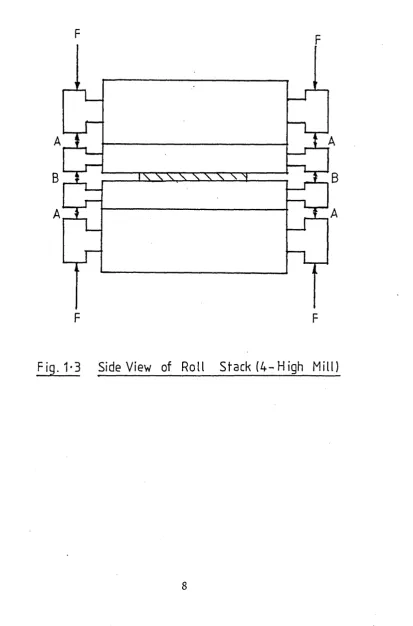
supported by one backup roll each, in a vertical plane -Fig. 1.3). It is a much more difficult matter to apply an ASC system to a Sendzimir type mill (this will be clarified later), and although several Sendzimir mills are known to be equipped with shapemeters, at this time it is believed that only one other mill is actively con sidering an AFC scheme. It is hoped that the work des cribed in this thesis will therefore lead to one of the first Sendzimir mill ASC systems ever to operate.
It should perhaps be mentioned at this point, that since the thesis includes work on an ongoing industrial development, some aspects of the work (especially the implementation of the scheme) will not be finished before the thesis submission date. Hence, it will not be
possible to include, say, operating results in the
F - Application of Rolling Load by Screwdown Systems
A ,B - See Text (Sect. 2*1)
A
B
A
F
F
[image:23.620.118.532.156.783.2]1.2 Means of Shape Control in Four-High Stands
If strip having good shape is rolled by a mill and found to have bad shape after rolling, the reason is that the cross sectional profile of the strip being rolled did not coincide with the profile of the roll gap (see
section l.l). There is a number of reasons why this may be so. Referring to figure 1.3? when a rolling load is applied, since the only support for the rolls is by means of their neck bearings, the rolls will bend giving a
’•crowned1’ profile to the strip (i.e. thickest, in the centre). Since cold rolled steel strip is normally re quired to have a small parobolic crowned cross section, this is acceptable in principle. Nevertheless, the amount of crown caused in the roll gap by roll bending must
accurately match the crown in the incoming strip, other wise bad shape will result. Workrolls are usually ground with parabolic crowns, carefully calculated so that under normal rolling conditions the roll gap profile will match the cross section of the incoming strip. Further crown is imparted to the workrolls in the form of ’’thermal camber" during rolling. This arises because the heat generated during rolling can more readily escape from the ends of the rolls than the centre, and the centre therefore expands more than the edges. Now, if the mill rolls are correctly ground for steady state rolling (including the effects of thermal camber), it can be seen that the roll gap profile will be incorrect whenever the rolls are cold
result when the rolls are not at their correct temp erature, or if the crown ground onto the rolls is in correct (which can occur due to roll wear even if it was originally correct), or if the profile of the incoming material is different from that for which the rolls are designed (which can often be the case, especially when material is bought from different suppliers), also the preceding stand in a tandem mill may have upset the shape if not scheduled correctly.
The foregoing description, in itself, suggests the normal methods of adjusting shape in rolling stands.
Firstly, to control thermal effects, differential cooling is often employed, whereby cooling sprays arranged at many points across the rolls are selectively switched on or off as required. This means of control is particularly
favoured by operators of aluminium rolling mills - see for example (4) - but is also used on steel mills. The major control on most mills where shape control is possible is to bend the workrolls during rolling. In the 4-high type of mill, this is usually achieved by hydraulic jacks situated between the roll chocks as indicated in figure 1.3« !,A n represents jacks placed between the backup roll and
workroll chocks, whilst MBM represents jacks placed
industry except in heavy plate mills (to the best of* the author’s knowledge).
The reasons for using a Sendzimir type of mill rather than a four-high mill for certain purposes will be outlined in Chapter 2, but the foregoing description of mechanisms for control of shape in four-high mills has been included here for completeness.
1.3 Description of the Present Project and the Thesis In the mid 1970’s two large Sendzimir mills were built at British Steel Corporation’s Shepcote Lane works. These mills are described in Chapter 2. Each mill is equipped with ASEA "Stressometer" shapemeter rolls which provide the mill operators with information about the shape of the strip being rolled (the shapemeters are also described in Chapter 2). It was decided at an early stage that these mills would eventually be furnished with closed loop automatic shape control schemes0 Likely suppliers of such schemes were contacted, but for various reasons BSC decided to develop the scheme locally; and so the project was born.
A. great deal of original work has been necessary to progress this project, as will be made clear in the
following chapters. Any collaboration with other workers which has taken place will also be made clear at the
appropriate points.
taining to the static behaviour of the mill stand and its various control actuators. These models attempt to predict the effects upon strip shape of any combination of mill actuator movements. The resultant information is used in Chapter
k
where a model is developed pertainingto the dynamic behaviour of all parts of the plant rele vant to shape control (i.e. the mill actuators, the
characteristics of the strip between the mill and the shapemeterj the shapemeter itself and its electronic systems, and the shape controller). Chapter
3
describes plant testing which was carried out to check the accuracy of the various models. The development of the control system itself is covered in Chapter 6, whilst Chapter 7 introduces the dynamic simulation methods used to test the various systems developed. (These were all developed by the author, as no dynamic modelling package was other wise available to him). Chapter 8 includes as much as can be said at the time of writing concerning the actualCHAPTER 2
CHAPTER 2
PHYSICAL DESCRIPTION OF THE SENDZIMIR MILL INSTALLATION 2,1. Introduction
The major limitations of the 4-high mill stand from the point of view of shape control are twofold. Firstly, any change made to the screwdown mechanism on the stand for purposes of gauge control, will cjiange the degree of roll-bending evident in the workrolls. This will cause a shape change in the strip leaving the mill, which may be significant for certain gauges and materials. Secondly, since roll bending is only applied at the roll hecks, only a limited amount of roughly parabolic bending is possible. This severely limits the amount of shape correction possible, and the forms of shape which can be corrected (e.g. on a 4-high mill no correction could be made to the "herringbone11 or "quarter buckle" shapes shown in fig. 1.2 by means of roll bending; and if differentialrcooling is available, even this is of limited use due to the magnitude of
corrective action possible and sometimes to the relatively long time constant involved). A further limitation of the 4-high mill becomes apparent if it is desired to take high reductions on hard materials (e.g. stainless steel).
extremely complex mechanical system, and the primary purpose of* this chapter is to describe the mechanics of* the system so that the later chapters on modelling can be readily reconciled with the plant. The following section describes the general layout of the mill stand, and this is followed by a section devoted entirely to a description of the control actuators, which are not at all easily
described in writingi The final section describes the operation of the ASEA "StressonLeter" shapemeter system.
2.2 Mechanical Description of the Sendzimir Stand
The Sendzimir mill permits the use of small diameter workrolls by providing massive support, in an extremely rigid housing. Various configurations are available, but the mills at BSC, Shepcote Lane, are of the twenty roll type. Figure 2.1 shows an end view of the roll stack
(or cluster) of such a mill, using standard notation for the various rolls. Each of the backup roll assemblies
(A-H, fig. 2 d ) is segmented into seven separate short rolls, with support to the housing being provided by a
Fig.2-1
Roll Stack Arrangement- (20-Roll Sendzimir Mill)
u Min
Housing-Saddle-
' \ ~ v\Roller Bearin
Shaft"—S
Short Roll
Segment
("Backi ng
B earing")
Second Intermediate Roll (ItoK)
First In te r. Roll (0 &P)
Backup Roll
• Assembly
the upper workroll is removed). The mill drive (from a single motor) is applied to the outer second inter-r
mediate rolls (l,K,L and N) and transmits to the workrolls by inter-roll friction. This means of construction provides great support to the thin workrolls, and unwanted roll
bending is minimized. The mill type under consideration is designated ZR21B-635 wherein uZn stands for the Polish
"Zimna11 meaning "cold", "R-1 stands for "reversing", lt2111 is an indication of the mill housing bore sizes, nBn
indicates a modification to the mill housing dimensions to allow slightly larger workrolls than standard to be used if required and "63!I is the mill width in inches (l600mm). The layout of the plant is indicated in figure 2.3*
To give an idea of scale a typical set of nominal roll diameter may be as follows:
Backing Bearings (A-H) 0.406 m
Second Intermiedi-ate (Drive) Rolls (I ,K,L,N)0.235 m Second Intermediate (idler) Rolls (J,M) O.23O m First Intermediate Rolls (0-R) 0.135 m
Workrolls (S-T) 0.075 m
Shapemeter
qj
c
r
X
o
n
2.3 Mechanical Description of the Mill's Control Actuators
The mill is equipped with various actuators which allow the cluster to be opened up for roll changing and strip threading, the pass line height to be adjusted (i.e. the path taken by the strip during rolling) and also per form functions of gauge and shape control. During the author's reading of the literature, no description of the operation of these actuators (other than the most rudimentary details, which would only be of use to those already in possession of the appropriate facts) could be found. Even Sendzimir's brochures appeared rather vague in this area. Therefore, many hours were spent in study ing BSC's sets of plant drawings, and also studying the plant itself, in order to gain sufficient insight into the working of these systems to allow them to be modelled. The information thus gleaned is described in this section, and the author has also passed it on in discussions with other workers, in this field, to help their work to
proceed (l4~l8).
Referring back to fig. 2.2, it will be recalled that each of the outer rolls (A to H) in the Sendzimir mill cluster is segmented into seven backing bearings, mounted on roller bearings, and running on a shaft supported by eight saddles which are bolted to the mill housing. Wherever the shaft passes through a saddle, it is keyed
O
o
«
w
nA M in fig. 2.4), since it is keyed to the eccentric disc, both shaft and disc -will rotate in the saddle bore together. This causes the centre of the shaft (C2 in fig.2.4 - which is also of course the centre of the backing bearings at each side of the saddle) to move around the fixed centre of the saddle bore (Cl in fig.2.4 - which is also the centre of the mill housing bore). Due to the geometry of eccentric motion, the locus of C2 is1 a circle about Cl, whose radius is equal to the eccentricity in the disc - this will not be proved here. Thus, rotation of the shaft causes the backing bearings at either side of the saddle to move
relative to the mill housing. Since the shaft is keyed t° an identical eccentric disc in each of the eight saddles, rotation of the shaft causes an identical motion at each saddle, and therefore the entire set of backing bearings on the shaft moves relative to the mill housing and
parallel with its original position.
2.3.1 Push-up System Operation
The lower backup roll assemblies (F and G in fig.2.1) each have the construction described above,, If figure 2.4 is taken to represent a saddle on shaft G, then the
electrical solenoid valve which controls the hydraulic push-up cylinder connected to the racks. The way in which this affects the magnitude of the roll gap is indicated by the arrows in fig.2.5o
The major function of the push-up system is to allow the mill cluster to be opened up for strip threading and roll changing. Under normal rolling conditions the racks are usually in the fully closed (down) position, and are not used for any control action.
2.3*2 Side Eccentrics Operation
The pairs of backup roll assemblies (A,H) and (D,E) at each side of the mill are equipped with similar
mechanisms to the push-up system described in the previous sub-ection. The main difference is that the operation is via electric drives and pinions situated only at; the
back of the mill. The shafts of assemblies A and H are simultaneously contra-rotated as described above, and so are the shafts of assemblies D and E. Note, however, that the two systems (A,H) and (D,E) are adjusted independently.
The function of these eccentrics is to allow the mill pass line to be correctly set (as otherwise the pass line would vary according to the combination of roll
2.3.3 Screwdown System Operation for Gauge Control
The term "screwdown" is somewhat misleading for a mill equipped with hydraulic cylinders, but it is still
employed by convention. It arises from the fact that until recent years, all four-high rolling stands employed
electrically or mechanically driven screws to position the rolls and vary the rolling load. Many modern mills
(including almost all Sendzimir mills) employ hydraulic "screws" which are in reality "rams".
The two upper backup roll assemblies (B and C in fig. 2.l) are equipped with an identical arrangement to that described for the push-up system in sub-section 2.3.1 above (and figc2.5 - inverted, and with the roll
designations for the upper half of the clusteri). The difference is that whereas the push-up system is used only for roll changing and mill threading, the screwdown system is used for control during rolling. It is used to control strip thickness (gauge) either manually by the operator or automatically as part of the automatic gauge control system shown in figure 2.3. In the latter case, the automatic system uses hydraulic servo valves to position the screwdown cylinders, in response to signals of strip gauge received from the X-ray gauges at each side of the mill.
housing, this motion remains essentially parallel even when it reaches the workroll. Therefore, compared with the four-high mill (section 1.2), there is very little effect upon strip shape due to making gauge changes. This is a primary advantage of the Sendzimir mill stand.
2.3.4 As-U-Roll Operation for Shape Control
For purposes of shape control, it is necessary deliberately to be able to bend the workrolls during
rolling (section 1.2). The system employed in the Sendzimir mill is referred to by Sendzimirs1 trade name MAs-U-Rolln
(since it allows roll bending Mas-u-rollM), this also
operates on the upper pair of backup roll assemblies, B and c *
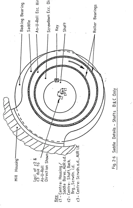
Each of the saddles supporting either of the two shafts B and C is fitted with an extra eccentric ring, interposed between the saddle bore and the screwdown eccentric disc as shown in figure 2.6. The eccentricity of this ring is much less than that of the screwdown disc
(typically less than 20 percent of screwdown eccentricity) since workroll motion required for shape correction is exceedingly small.
The As-U-Roll eccentric ring at each saddle can be rotated independently of the shaft and screwdown system
H
ou
si
ng
cn c roCD CD cn c cn u c inc c □
i j UJ
l_J l_J
LU LU
. c
cD ° FO " 0£o "O
“O OJ
ro </)1 l_l_J
0 0 < 0 0
in cn c c_ 0) CD CD CD
in in ro
[image:41.614.90.544.29.735.2]Housing
*o"O
concerned, so that its teeth mesh with the four appropriate check pieces (one on each side of the As-U-Roll rings at the corresponding saddles on shafts B and C). The mill operator can raise or lower each of the eight As-U-Roll racks independently, by operating electric solenoid valves. These supply a hydraulic motor for the selected As-U-Roll
system, which raises or lowers the rack by a worm and rack arrangement.
As one As-U-Roll rack is raised or lowered, it
rotates the As-U-Roll eccentric rings at the corresponding pair of saddles on shafts B and C via the check pieces
(fig.2.8). Referring back to fig.2.6, this causes C3 to move around the fixed Cl on a circular path whose radius equals the eccentricity in the As-U-Roll ring. Since we are assuming that the screwdown system is not being
operated at this time C2 will follow a ’’parallel*1 circular path to C3 . Now C2 is the centre of the shaft and of the backing bearings on each side of the saddle under con
sideration. Therefore by moving one As-U-Roll rack only,
the position of the backup roll assemblies B and C is changed, relative to the mill housing only adjacent to the saddle
Racks at Zero Position
- ---- .—
-w
I_ _J L. U LT (-4 1— i r_j j_ i m . "j— TL- _i L_. _1
21R
11R
WR
A fte r Motion (Grossly Exaggerated)
2IR
It is worth reiterating that the design of the Sendzimir mill minimises interaction between gauge and shape control systems. When a shape change is made, only the As-U-Roll eccentric rings move, forcing a suitable
profile onto the workrolls. The resultant change in gauges is extremely small, due to the small eccentricity in the As-U-Roll rings, and the fact that there are constraints upon the amount of As-U-Roll control possible (this will be discussed later). The automatic gauge control system is fast-acting compared with shape control, and if a shape change does cause a net gauge change visible to the AGC system, it will be corrected very quickly. On the other hand, when a gauge change is made, only the screwdown eccentric discs move (rotated by the shafts B and C) and as discussed in sub-section 2.3.3 above, the discs move an identical amount at each saddle. Thus the bending profile on the workroll is virtually unchanged, and an almost pure gauge change results.
2.3.5 First Intermediate Rolls for Shape Control
Although the As-U-Roll system permits a much wider range of bending profiles to be forced onto the workrolls than is the case in a four-high mill, it is not as flex ible as may at first appear. This is due to mechanical constraints upon the amount of bending which can be
tolerated by the backup shafts B and C and the other rolls in the cluster under rotating conditions. The As-U-Roll actuators are set by the operator according to scales
mill and the mill engineers lay down a constraint that
the position of any As-U-Roll actuator shall not deviate by more than l-g- of these units from the mean position of its two neighbours. Large gradients and sudden maxima and minima are therefore ruled out.
To allow much more freedom.of control at the critical areas of the strip edges, a second means of shape control is provided. The first intermediate rolls 0 and P (in fig.2.1) are tapered off at the front of the mill, and Q and R at the rear as shown in figure 2.10. These tapers can be moved laterally into or out of the cluster as in dicated in the figure. The upper and lower pairs of rolls are independently adjustable, thus allowing separate control of shape at the front and back edges of the strip. The
motion is imparted to these rolls by means of internally threaded thimbfes which run on external threads cut on non-rotating extensions coupled to the back ends of the first intermediate rolls. The thimbles are laterally constrained with respect to the mill housing, so that if the thimbles are rotated, the screw action of the threads will move the first intermediate rolls in or out. The drive to the thimbles is by chain from hydraulic motors controlled by switches on the mill operator's desk via solenoid valves. (Described in more detail in Chapter 4).
2nd Intermediate roll
1st Intermediate ro ll
W orkroll
Upper IR shift
sy /s.
W orkroll 1st Intermediate ro ll
2nd Intermediate ro ll
Lower IR shift
Fiq2'1Q SENDZIMIR M IL L FIRST INTERM EDIATE ROLL ADJUSTMENT
Hardened, shrunk on steel rings
Steel core
Transducers in m illed grooves
into the strip, and it is known that the As-U-Roll system alone cannot produce two inflexions in the workroll, due to the mechanical constraints (20). Also, tapered
intermediate rolls have recently been introduced for shape control in four-high mills by Hitachi (2l), thus forming the six-high mill, which is making very rapid progress now in Japan.
The automatic shape control system for the Shepcote Lane mills will incorporate control of the As-U-Rolls and the first intermediate rolls, although initial effort has been directed at the As-U-Roll systems for various reasons which will become apparent.
2.4 The ASEA Shapemeter System
To conclude this chapter, a brief description will now be given of the system which measures strip shape on
the mills in question. The system comprises the transducer itself, which takes the form of a pass-line roll, and the electronics necessary to process the transducer signals and provide a shape display in the operator's pulpit.
2.4.1 Description of the Stressometer Roll
One Stressometer measuring roll (4,5) is placed at each side of the mill, approximately 2.91m from the roll gap. Each roll takes the form of a solid core, having
the correct height. These transducers are then covered by 31 hardened steel rings which are shrink-fitted over
the core so as to pre-stress the transducers. Each ring is 32mm wide, and is separated from its neighbours by small gaps of typically 20 to 40 microns. Each ring, with its group of four transducers therefore forms an independent measuring zone. The four transducers in each zone are connected together in such a way that the pre stressing forces due to the shrunk-on steel ring, thermal effects, centrifugal force, bending of the roll due to strip tension and also stray magnetic effects are all effectively cancelled out. This leaves only the force on each zone due to the tension in the strip passing over it to be measured (because this affects only one transducer at a time, whereas the above mentioned are all common mode effects).
The roll is mounted in roller bearings, and all the transducer signals are brought out by means of a multi pole silver sliprixjg and brush system at the rear of the mill.
2.4.2 Description of the Signal Processing
The primary windings of the transducers in each zone are connected in series, ahd energized with a 2kHz signal. If the four transducers in a zone are labelled A,B,C and D sequentially around the roll, then the secondary windings (the transducers operate on the principle of magneto striction) are connected in series as follows
each zone •will take the form of an amplitude modulated wave, having a carrier frequency of 2kHz, a modulating frequency dependent upon strip speed, amplitude which exhibits four pulses per revolution of the
roll-alternatively less than and greater than the carrier amplitude, and of a magnitude dependent upon the load placed on the zone by the strip. This signal from each zone is fed to one channel of the signal processing electronics. Here, it is fed through phase-sensitive rectifiers and filters to obtain a direct voltage
proportional to the radial force on the measuring zone.
In order to obtain good filtering characteristics, a variable time constant is used in the signal electronics. This is selected automatically as a function of strip speed (Table 2.l).
Strip Speed
(m/s )
0-90%
Time (s) Response0.3 - 1 10.0
1 - 2 3.3
2 - 5 1.7
5 - 1 5 0.7
15 - 50
0.25Table 2.1
Having obtained values F__ for the radial x x=l,31
force exerted by the strip on each measuring zone (N), £he processing proceeds as follows:
Let F m = mean force (N)
= stress in strip at zone x (Nm 2 ) — 2
cT m = mean stress (Nm )
— 2
Z^a-'
f = deviation of stress at zone x from mean (Nm )xi :
shapeT s total strip tension (N ) t = strip gauge (m)
w = strip width (m)
N = number of shapemeter rotors covered by the strip.
The parameters T, t and w are available to the
shapemeter electronics, therefore o' can be calculated asm
(Nm-2) m w. t
1 N
also F = ~ m N F x (N) x=l
Now
cr
u m _<y
F m “ Fx®"m Therefore cj"x = F . ——
x Fm x=l,31 (Nm”2 )
The quantity ^jn is evaluated by the elctronicss and
Fm 2
so can be found for each zone. (Nm” )
Then finally
A
ct = cr -o'
— 2
The 31 values are then scaled in N mm and dis played to the mill operator by means of 31 edge-meters arranged side by side. The range of the display is
+ -2
- 200 N mm for each zone.
CHAPTER 3
STATIC MATHEMATICAL MODEL OF THE MILL 3•1 Introduction
This chapter considers the non-dynamic aspects of the mill stand itself, including the various actuator mechanisms described in section 2.3- The purpose of the model is to predict, from any possible combination of actuator movements, the magnitude of the effects upon the transverse internal stress distribution of the strip
leaving the roll gap (fig.3»l)« Clearly, for shape control considerations, the major emphasis is placed upon a per turbation analysis of the As-U-Roll and first intermediate roll taper effects upon the strip shape. However, it should be borne in mind that the settings of the screwdown and
side eccentric systems affect the range of control of the shape control actuators by modifying the roll stack
geometry. A. unique feature of the present model is that it attempts rigorously to define these effects, by careful modelling of the complex mechanical mechanisms by which the distribution of rolling load throughout the cluster is affected when any of the mill’s actuators is moved. In addition, every effort has been made to keep the model non iterative, so that the long computation times associated with such models are avoided. Some details of the
Screwdown
As-U- Rolls
Side Eccs.
11R Tapers
Roll Dias.
Cambers
Strip Gauge
Strip Width
Tensions
Reduction
Yield Stress
r
Actuator
Chapter 3
Changes
Model
Fig.3*1 Function of Static
Shape
Change
List of principal symbols, abbreviations and notations to be found in this chapter and Appendices 1 to 4
Subscripts (unless otherwise defined) General subscripts used
are;-B Quantity refers to backing bearings
2 Quantity refers to second intermediate rolls 1 Quantity refers to first intermediate rolls W Quantity refers to workrolls
N Used as a count (i.e. N = 1,2,3»^... etc.) Common second subscripts used are:
-L Quantity refers to the Left-hand side or end R Quantity refers to the Right-hand side or end
S Quantity refers to the area over the strip being rolled T Refers to the top half of the roll stack ^ (used B Refers to the bottom half of the roll-stack ) ^j) 0 Indicates mill actuator datum positions (used with
L ^
S1S2 D Drive roll)(used with D_)
)
1 Idler rolljMain Variables and Abbreviations
Motion of upper central backing shafts (roll B) towards centre of upper central second intermediate roll(j) at the saddle from front of mill (i.e. due to motion of the As-U-Roll rack). (m) (close approximation)(positive for roll B moving towards roll J ).
As-U-Roll
General functions defined in beams-on-elastic foundations theory (Appendix l)
B.O.E.F. Beams-on-Elastic Foundations
c Camber off diameter of roll specified by subscript s.
S
(m)
BVN
AUR A BA x
Maximum diameter (including camber) of roll specified by subscripts s (m)
e Base of natural logarithms
eaSesse Eccentricity of As-U-Roll rings, screwdown and side Eccentric Discs respectively (m)
— 2 E Young5 s Modulus for all rolls (Nm ).
ECF Abbreviated form of nend-conditioning-force" E, ) Intermediate values defined in beams-on-elasticIs
,
g ^ foundations theory (Appendix l).2s ^
F Value of concentrated force, subscripted as ap propriate, (N) (positive downwards)•
Values of force defined for roll specified by subscript s in b.o.e.f. theory (N).
F ' 0s p»
0s FOAs FOBs
^ G mill gain matrix (N mm )— 2 P
lN "fch
h^,. Strip input gauge over the centre of the N shape meter rotor covered by the strip, (m)
Strip output gauge corresponding to h^. (m)
h. ) Strip general entry and exit gauges used in rolling
x
h ^ theory (m))
I Second moment of area of roll specified by subscript S s. Roll assumed cylindrical and of diameter Dg (m )4
r\
Yieldstress of strip in roll gap (Nm*" )} v a r i a b l e as k(/0
Foundation modulus defined in b.o.e.f. theory (Appendix l) for roll specified by subscript s_
— 2
resting on roll specified by subscript sQ. (Nm ) Taper off base (i.e. uncambered) diameter of first intermediate rolls. (m)
Length of H R tapered portion (ra) Length of each backing bearing, (m)
Length of tapered section of first intermediate rolls which is slid into the cluster, (m)
Width of each shapemeter rotor, (m) Strip Width, (m)
Total roll length (m). (Length of non-tapered portion of lIRs).
Unsupported length of workroll overhanging each edge of the strip. (m)
Abbreviated form of "left-hand". Note that the "left-hand" end of any roll is at the front of the mill.
Distance between centres of rolls specified by sub scripts s^ and s^ (used in cluster angle and force analysis), (m)
As-U-Roll Rack position (operator's units)
(positive downwards) side eccentric position (operator's units)
M s screwdown rack position ( " " )
M Even number of points (symmetrical about the vertical ® 1
centre line of mill and equally spaced) at -which deflection is calculated for roll specified by subscript s^.
Pg Pitch of backing bearings (m) P,p Total Rolling Load (N)
P' Distributed Rolling Load (Nm""’**)
q Value of uniformly-distributed loading, subscr
wards)
subscripted as appropriate, (Nm "**) (positive
down-QA \ Values of shear defined in b.o.e.f0 theory
s
)
Q' ) (Appendix l) for roll specified by subscript s. (N) (Positive when acting upwards on the left of a section) A s
0"As %
s
R Undeformed roll radius (m) R' Deformed roll radius (m)
RH Abbreviated form of "right-hand"
r A,r ,r A* s s p Gain of As-U-Roll, screwdown and side eccentric’ actuators (rad/operator's unit)
— 2
s Normal rolling pressure (Nm ) (Variable as s (/0 ) . T.,T Entry & Exit Tensions (N)i * o *'
T.',T'
i o
" " Tension stresses (Nm-2)WR Abbreviated form of "workroll” w
N
Strip width (m) used in rolling theory. "fch
Distance of front edge of N backing bearing along second intermediate roll. Measured from
front of mill. (A zero preceding the nNn indicates that the measurement is taken at zero As-U-Roll travel), (m)
Im-1 M Array of distances of the Mg points from the
s front of the mill, (m)
x Distance from front of mill of point of
sFn |n ^ j application of concentrated force
s sF acting on roll specified by subscript s. (m)
N Definition of workroll at LH edge of stripdue to N element of array F^(J^p). (m)*t h
Deflection of workroll at RH edge of strip du e to N b JU V/ ill element of array Fw (J^p).X JL b U X U J L Jl U J » y
(m)
xM
M=1,M
Deflection of roll specified by subscript s at the section x.,.M (m)
N A number of algebraic reduction factors used in section 3-9-21, defined as required
R
Ah
NN=1, JH
p.u. Reduction of strip gauge due to rolling
Differential elongation (w.r.t. mean) of *th filament of strip corresponding to N
covered shapemeter rotor centre from front of mill. (m)
Ao'.
N Differential stress (shape) in the above^A’^s’^p Deviation of* As-u-Roll, Screwdovra. and side eccentric rings/discs from datum position
(rad). (positive when clockwise viewed from the front at shafts A,B,G,H)
0T Deflection angle corresponding to yT . (rad.)
LN N
\
Deflection angle corresponding to yv, . (rad.)
0^
Deflection angle corresponding to y^. • (rad. )XM XM
) Cluster angles defined in figure 3*16 (rad.)
0
1R-
8R)IX s See E (m-1 )
yM
Co-efficient of friction in roll gap.i)
Poisson's Ratio for roll material..
0
’’Rotation” of screwdown, side eccentric discss p s
to achieve datum from ’’horizontal”. (rad.)
Angle subtended at workroll centre by the arc of contact between exit plane and some plane of interest (rad.)
including:
(
$
= 6
(exit plane) = 0(rad.) ( °(
j
&.
=6
(entry plane) = arc of contact of strip in( roll gap (rad.)
3.2 Modelling of the Control Actuators
This section describes that part of* the model which determines the effect upon the cluster geometry of moving the eccentric actuators (the first intermediate roll tapers are not discussed until section 3*8, as their effect is more sensibly included there). The next section considers the implications of the cluster geometry in
terms
ofrolling load distribution.
Consider first the upper half of the mill cluster. Section 2.3 has made it clear that when any of the ec centric actuators is moved (excepting here the push-up system, which acts’only on the lower half of the roll stack) the centres of the backing shaft assemblies A to H
(fig.2.1) will move relative to the fixed mill housing and relative to each other. Furthermore, perusal of sub-sections 2.3*3 and 2.3«^ (and the analysis below) will show that since the eccentrics at shafts B and C always move together, a line joining the centres of shafts B and C will remain horizontal at all times. Therefore, given a knowledge of the roll diameters, the set of five parameters shown in figure 3*2 is necessary and sufficient to specify the complete geometry of the upper half of the cluster. (
ft
is itself a function ofthe other 3 parameters). Note that the roll diameters are modified by roll flattening under the influence of rolling load. These effects are included in section 3-^
Q
oo
OC
CL
i/>
o "O
CD
d> -i—00
V_J
(D □c
<u
Cl
CL
ID
O >N
£_
QJ
e
o
Of
I
D
X
00
aj
-4—
cu E
roc_
ro
CL
CNI
Let us establish a datum position from which all actuator movements will be measured. The positions of the operating mechanisms for the screwdown, push-up and side eccentric systems are displayed to the mill operator on scales graduated in arbitrary units from zero to ten. The zero positions correspond to the fully open mill position (maximum roll gap) and these will be taken as the datum position. The As-U-Roll rack positions are displayed on scales of
-5
divisions (+3 divisions being the position to which the rack is fully lowered), and the centre zero positions are taken as the datum here. The physical meaning of the datum position in terms of eccentric rotations is illustrated in figure 3*3» At each backing shaft position, Cl represents the (fixed) housing bore centre, C2 the centre of the backing bearingshaft assembly at the datum position and C3 (shafts B and C only) the centre of the inner diameter of the As-U-Roll eccentric ring. All eccentric movements in figure 3-3 have, of course, been grossly exaggerated for clarity, typical values of eccentricity being of the order of 9mm, 4.3mm and 1.3mm for the screwdown, side eccentric and As-U-Roll respectively (compared with the typical backing bearing diameter of 4o6mm). The various angles of rotation of the eccentric discs in fig.3»3 are defined below, and then the set of measurements between shaft centres (fig.3«2) is derived. At the datum position, the parameters shown in figure 3*2 will be referred to as g , Lg ^ g and L^ g • These can be calculated
0 0 0 0 0 0 0 0