International Journal of Emerging Technology and Advanced Engineering
Website: www.ijetae.com (ISSN 2250-2459,ISO 9001:2008 Certified Journal, Volume 4, Issue 12, December 2014)
159
Seismic Response Analysis of Earth Dams Embanked with
Soil-based Controlled Low-Strength Materials Using Finite Element
Method
Huang Li-Jeng
Associate Professor, Department of Civil Engineering, National Kaohsiung University of Applied Science, 80778, Taiwan, Republic of China
Abstract—This paper presents the seismic response analysis
of earth dam embanked with sustainable material, a controlled low-strength material (CLSM), using finite element (FE) methods. The Young’s moduli of CLSM are obtained from laboratory tests for different ages including 1, 7, 28 days and two different binder mixtures. Two-dimensional planar strain is employed in the FE formulation of transient analyses. Typical examples will be employed for comparison study of earth dam embanked using CLSM and sandy soil or concrete. Emphasis is put on the time history responses of the earth dam embanked with with CLSM at different ages, with different binder mixtures and compared with different materials. Programs will be coded in MATLAB and the numerical results will be checked with exact solutions. Results are expected to assure the applicability and advantages of CLSM as a suitable sustainable material employed for earth embankment in geotechnical engineering.
Keywords—Controlled low-strength material (CLSM), Dynamic analysis, Earth embankment, Finite element method (FEM), Seismic Response Analysis.
I. INTRODUCTION
Static and dynamic stability of earth dams and embankments are important problems in the geotechnical engineering. Taiwan is located at the Circum-Pacific Seismic Belt and thus many earthquakes occur each year. The horizontal and vertical accelerations induced by earthquakes usually leads to liquefaction of perfectly and/or partially saturated stratum as well as softening, peel-off, separation and deposit of rocks and embankments. There are several recorded cases in the past that depict damage or collapse of earth embankments due to earthquake-induced oscillation (Ambraseys, 1960; Seed et al. 1978) [1, 2].
Recently, sustainable materials have been widely studied and developed especially for construction, highway and civil engineering. Controlled low-strength material (CLSM) is commonly used as backfilled materials. It would be a friendly environment-cheap material and typically consists of small amount cement, supplementary, fine aggregates, and a large amount of mixing water.
Self-compacting/ -leveling, significantly low strength, as well as almost no measured settlement after hardening are remarkable characteristics of CLSM [3]. Recent studies have reported that maximum CLSM strength of approximately up to 1.4 MPa is suitable for most of backfilling applications when re-excavation is required [4, 5] It is also recommended that depending upon availability and project requirements, any recycle materials would be acceptable in production of CLSM with prior tests its feasibility before uses [3]. Literature reviews showed that on-site residual soil after pipeline excavation may be an alternative source for fine constituent in production of soil-based CLSM, effectively used as backfill around buried pipelines [6, 7]. Schmitz et al. have conducted experimental and computational works on the use of CLSM as abutment backfill [8]. The authors also conducted some preliminary studies on engineering properties of CLSM [9-10].
CLSMs are usually employed as the materials for backfilling or embankment requirement. In order to assure the CLSM to be confident material for backfilling the static and dynamic mechanical behaviors should be clearly understood. Numerical analyses based on finite element methods (FEM) or boundary element methods (BEM) might become available and convenient tools. The static parts and the steady-state elasto-dynamic analyses have been verified well [11, 12].
International Journal of Emerging Technology and Advanced Engineering
Website: www.ijetae.com (ISSN 2250-2459,ISO 9001:2008 Certified Journal, Volume 4, Issue 12, December 2014)
160
II. EXPERIMENTAL RESULTS
2.1 Materials used, and mix proportion
Selection of materials for the CLSM mixture in this study consisted of fine aggregate, type I Portland cement, stainless steel reducing slag (SSRS), and water. Fine aggregate was formed by well blending between river sand and residual soil with a given proportion (e.g., 6:4, by volume) for grading improvement. The soil was obtained from a construction site. The experimental work was conducted on two binder content levels in mixtures (i.e. 80- and 130 kg/m3). The water-to-binder ratio was selected via few trial mixes until the acceptable flow-ability for CLSM of 150300 mm were achieved. The detailed can be referred in [10].
2.2 Testing results
(a) Stress-strain behavior and modulus of elasticity at different ages
[image:2.612.336.554.225.374.2]An axial load from a low-capacity hydraulic machine (100 kN) was slowly and uniformly applied to the capping specimens until failure at a constant displacement rate of 0.51 mm/min. The strain after each loading increment was measured by reading on two dial gages, graduated in 0.01 mm. It can be observed that the longer ages the higher UCS was obtained along with a drastic change in shape of stress-strain curve, as typically shown in Fig. 1. The results imply that at early ages, CLSM behaves as a soil material with more ductile characteristic, but with long-term ages the material acts more like concrete, with higher strength and lesser strain (brittleness).
Figure 1 Stressstrain response for Mix-1 at 1-, 7-, and 28 days.
(b) Modulus of elasticity of different mixtures
[image:2.612.58.277.503.613.2]The elastic modulus was calculated as the slope of the secant line drawn from the origin to a point on the stress-strain curve at 40% peak stress. The values of 28-day elastic moduli of all CLSM mixtures were displayed in Fig. 2. The B80 and B130 denote for mixture series containing 80 and 130 kg/m3, respectively.
Figure 2 28-days Elastic moduli of CLSM with different mixtures
III. FINITE ELEMENT ANALYSIS OF EARTH EMBANKMENT
3.1 Problem description
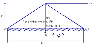
An earth embankment with length L , height H is considered (Figure 3). Table I lists dynamic properties of different embankment materials including soil, CLSMs, and concrete [8, 10].
[image:2.612.355.538.514.607.2]International Journal of Emerging Technology and Advanced Engineering
Website: www.ijetae.com (ISSN 2250-2459,ISO 9001:2008 Certified Journal, Volume 4, Issue 12, December 2014)
161
TABLEIDYNAMIC PROPERTIES OF DIFFERENT BACKFILL MATERIALS
Dynamic Properties
E (GPa)
(kg/m3)
G() (GPa)
Soil 0.10 0.3 1745 0.0385
CLSM(1 Day) 0.12 0.25 2017* 0.048 CLSM(7 Days) 0.14 0.25 1899* 0.056 CLSM(28 Days) 0.47 0.25 1678* 0.188 CLSM(B80/30%) 0.27 0.25 1695* 0.108 CLSM(B130/30%) 0.87 0.25 1800* 0.348 Concrete 25 0.2 2322 10.4167 * air-dried
Data collected from Ref: [5] and [8]
In dynamic analysis, three material properties, Young’s modulus (or Shear modulus), Poisson’s ratio and density, affect the characteristics of the embankment zone [13]. To simulate the seismic responses of the embankment zone subjected to time-varying ground motion caused from the rigid retaining wall, we consider boundary conditions to be traction free on the two sides of slope and fixed displacements along the bed of earth embankment. When the ground subjected to earthquake motion with ag(t), the
structure is exerted with an inertia effect with the same magnitude but in reverse direction..
Since there are a lot dynamic responses for all of region can be observed, we concentrated at the horizontal time history of displacement, velocity and acceleration of the most interesting point located at near the left upper corner.
3.2 Basic assumptions
The basic assumptions of numerical analysis are:
(1) Foundation of embankment bed is perfectly rigid; (2) Embankment zone is homogeneous ad isotropic and is
in the state of plane strain;
(3) Materials of the embankment are linearly elastic;.
(4) Structures considered are all within small amplitude oscillations
3.3 Finite Element Formulation
We can deduce the general finite element equations of equilibrium in the matrix form as [14, 15]:
} { } ]{ [ } ]{
[M x K x f (1)
Where [M],[K]denotes the global inertia and stiffness
matrix, {x} and {f}denotes the nodal degrees of freedom ad nodal loads of the finite element system.
If the dynamic system is subjected to ground acceleration, ag(t), Eq. (1) becomes
) ( } ]{ [ } ]{ [ } ]{
[M x K x M Lag t (2)
Where {L}[1 1 1]Tis a Nx1 column vector.
Introducing state vector
)} ( { )} ( { )} ( { t x t x t Z
(3)
Eq. (2) can be expressed in a form as the state equation
)} ( ]{ [ )} ( ]{ [ )} (
{Z t A Z t B ut
dt
d
(4)
Where the state matrix [A] , input matrix [B], and input vector {u(t)}, are defined as
) ( } ]{ [ )} ( { 1 ] [ ] 0 [ ] [ ] [ 1 ] [ ] [ 1 ] [ } [ ] 0 [ ] [ t g a L M t u M B C M K M I A (5)
Eq. (4) is linear first-order simultaneous ordinary differential equations and can be solved by fourth-order Runge-Kutta scheme when the initial conditions
T x x T
z(0}} {{ (0},{ (0}}
{ are specified. In the seismic response analysis we usually assume zero initial conditions, i.e., the system is at rest before ground excitation [16].
IV. NUMERICAL RESULTS AND DISCUSSION
4.1 Validity Check of Finite Element Models
Before we apply the finite element scheme to analyse the seismic response analysis of earth embankments using CLSMs we first check the FEM solver by applying it to a geotechnical problem of earth dams of soils which possesses analytical solution.
International Journal of Emerging Technology and Advanced Engineering
Website: www.ijetae.com (ISSN 2250-2459,ISO 9001:2008 Certified Journal, Volume 4, Issue 12, December 2014)
[image:4.612.79.266.171.261.2]162
Figure 8 Seismic excitation of an earth embankmentWith the following dimensions and properties [17]:
3 / 037 . 4 , 45 . 0 , 2 / 6 10 037 . 4 , 900 , 300 ft lb ft lb G ft L ft H
The exact solution obtained by the wedge theory is (Das and Ramana, 2011) [13]:
d t n g a t n J n n H z n J n t z
u ( )sin[ ( )]
0 ) ( 1 )] / ( [ 0 2 1 ) , ( (6)
Where J0,J1 is the Bessel function of the first kind of
zero and first order, respectively;nare the zeros of the
frequency equation, J0[nH /G]0 ; and
n ( n/H) G/ is the undamped natural circular frequency of the embankment corresponding to the nth mode of vibration.
From eq. (6) the relative velocity response, u(z,t) ,
relative acceleration, u(z,t), can be obtained by direct differentiation with time. The absolute acceleration is given by ) ( ) , ( ) ,
(zt u z t ag t abs
u (7)
Though Clough and Chopra (1966) [17] had attempted use 100 CST (Constant Strain Triangular) elements with 66 nodes to conduct a FEM analysis, here when finite method is employed for the first trial, totally 30 CST elements with 26 nodal points are selected for FE mesh of the domain. The 11 nodal points on the ground are fixed and we have a system with 2x15=30 degrees of freedom of nodal displacement (Fig. 9).
Figure 9 Finite element mesh of the earth dam
The validity test was conducted by calculating the horizontal dynamic responses of the crest of earth embankment (Node 15) using of two different ground accelerations of earthquake:
(a) 1940 El-Centro ground acceleration:
The acceleration of 1940 N-S component of El-Centro ground motion can be observed in Fig. 10. We employ
sec 02 . 0
[image:4.612.360.540.296.356.2]International Journal of Emerging Technology and Advanced Engineering
Website: www.ijetae.com (ISSN 2250-2459,ISO 9001:2008 Certified Journal, Volume 4, Issue 12, December 2014)
[image:5.612.67.269.156.518.2]163
Figure 10 Exact and FEM results of seismic responses of horizontalrelative displacement, relative velocity, relative and absolute accelerations of crest of earth embankment due to 1940 El-Centro
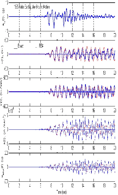
ground excitation. (b) 1995 Kobe ground acceleration:
The acceleration of 1995 Kobe ground motion can be observed in Fig. 11. We employ t0.005secand 4000
records of ground motion to compute the exact and FEM solutions along with Runge-Kutta scheme. Numerical solutions converge and agree well with the exact solutions from 0 sec to 10 sec as shown in Fig. 11. The results of relative displacement are the best, while relative velocities and relative accelerations become worse.
Figure 11 Exact and FEM results of seismic responses of horizontal relative displacement, relative velocity, relative and absolute accelerations of crest of earth embankment due to 1995 Kobe ground
excitation.
4.2 Comparison study of CLSM embankment materials at three different ages
[image:5.612.343.543.159.489.2]International Journal of Emerging Technology and Advanced Engineering
Website: www.ijetae.com (ISSN 2250-2459,ISO 9001:2008 Certified Journal, Volume 4, Issue 12, December 2014)
[image:6.612.73.262.183.532.2]164
After 28 days the CLSM can reach over two times of the natural frequencies of 1-day CLSM and soil.Figure 12 FEM results of seismic responses of horizontal relative displacement of crest of earth embankment by soil, concrete and CLSM with three different ages due to 1995 Kobe ground excitation. 4.3 Comparison study of CLSM embankment materials with
two different binder mixtures
The comparison study of dynamic responses of earth dams embanked with CLSM with three-ages subjected to earthquake. 1995 Kobe ground motion is employed for numerical analysis and only the horizontal displacements are displayed as shown in Figure 13. Figure 13 depicts that computed time-history of relative displacements for two binders of CLSM.
[image:6.612.347.537.199.488.2]It can be observed that the frequencies of B130/30% are higher (and thus periods are lower) than those of B80/30% and both are higher than those of soil. The maximal relative displacement of B130/30% is also lower than that B80/30%.
Figure 13 FEM results of seismic responses of horizontal relative displacement of crest of earth embankment by soil, concrete and CLSM with two different binders due to 1995 Kobe ground excitation
V. CONCLUDING REMARKS
Numerical calculation of seismic responses (displacement, velocity and acceleration) of CLSM embanked earth dam shows that finite element can provide satisfactory results. This FE analysis for earth dam embanked with CLSM forms a basis for future of spectra analysis of seismic response for the structure. In addition, numerical test studies show that:
International Journal of Emerging Technology and Advanced Engineering
Website: www.ijetae.com (ISSN 2250-2459,ISO 9001:2008 Certified Journal, Volume 4, Issue 12, December 2014)
165
(b) Consideration of dynamic characteristics of earth damembanked with CLSM,
CLSM(B130/30%)( E0.87GPa, 0.25,
3 / 1800kg m
) shows to be a good selection for embankment material providing as temporary engineering applications.
REFERENCES
[1] Ambraseys, N. N. 1960, On the Seismic Behavior of Earth Dams. Proc. 2nd World Conf. Earthq. Engng., Tokyo, 1, 331-345.
[2] Seed, H.B., Makdisi, F. I. and DeAlba, P. 1978. Performance of Earth Dams During Earthquakes. J. Geo. Engng. Div., ASCE, 104(GT7), 967-944.
[3] ACI-229R, 2005. Controlled-low strength materials (Reproved 2005), Farmington Hills (MI).
[4] Lachemi, M., Şahmaran, M., Hossain, K. M. A. and Lotfy, A. 2010. Properties of controlled low-strength materials incorporating cement kiln dust and slag. Cement and Concrete Composites, 32, 623-629. [5] Finney, A. J., Shorey, E. F. and Anderson, J.2008. Use of native soil
in place of aggregate in controlled low strength material (CLSM), International Pipelines Conference 2008, Atlanta, Georgia, United States, 1-13..
[6] Howard, A., Gaughan, M., Hattan, S. and Wilkerson, M. 2012. Lean, Green, and Mean: The IPL Project. ICSDEC 2012: American Society of Civil Engineers, 359-366.
[7] Schmitz, M. E., Parsons, R. L., Ramirez, G. and Zhao, Y. 2014. Use of controlled low-strength material as abutment backfill, Technical
Report K-TRAN: KU-02-6, The Kansas Department of
Transportation, Topeka, Kansas, University of Kansas, U.S.A. [8] Sheen, Y. N., Huang, L. J., and Le D. H., 2014. Engineering
properties of controlled low-strength material made with residual soil and Class F fly ash, 3rd International Conference for Advanced Materials Design and Mechanics and Workshop on Android Robotics, Paper No. 54, Singapore, May 23-24, Paper ID 54.
[9] Huang, L. J., Sheen, Y. N. and Le, D. H., 2014. On the multiple linear regression and artificial neural networks for strength prediction of soil-based controlled low-strength material, 3rd International Conference for Advanced Materials Design and Mechanics and Workshop on Android Robotics, Paper No. 55, Singapore, May 23-24. Paper ID. 55.
[10] Sheen, Y. N., Hsiao, D. H., Huang, L. J. and Le, D. H., 2014. Stress-strain behavior of soil-based controlled low-strength material, the International Conference on Green Technology for Sustainable Development 2014, Ho Chi Minh, Viet Nam, October 30 - 31, Paper ID 130..
[11] Huang, L. J., Sheen, Y. N., Hsiao, D.H. and Le, D. H., 2014. Quasi-steady analysis of excavation backfilled with soil-based controlled low-strength material using finite element and boundary element methods, the International Conference on Green Technology for Sustainable Development 2014, Ho Chi Minh, Viet Nam, October 30 - 31, Paper ID. 124.
[12] Huang, L. J., Sheen, Y. N., Hsiao, D.H. and Le, D. H., 2014. Steady-State Elastodynamic analysis of excavation backfilled with soil-based controlled low-strength material using finite element and boundary element methods, The Annual Conference on Engineering and Technology (ACEAT) 2014, Osaka, Japan, October 15 - 17, Paper ID. 105.
[13] Das, B. M. and Ramana, G. V., 2011. Principles of Soil Dynamics, 2nd edition, Cengage Learning.
[14] Desai, C. S. and Abel, J. F.1972. Introduction to the Finite Element Mehod: A Numerical Metrhod for Engineering Analysis. Litton Educational Publishing, Inc.
[15] Rao, S. S., 1982. The Finite Element Method in Engineering, Pergamon Press.
[16] Hart, G. C. and Wong, K. 2000. Structural Dynamics for Structural Engineers. John Wiley &Sons, Inc.