International Journal of Emerging Technology and Advanced Engineering
Website: www.ijetae.com (ISSN 2250-2459, ISO 9001:2008 Certified Journal, Volume 8, Issue 1, January 2018)
104
Link Adaptive Multiuser MIMO System with MRT Precoding
Technique and Limited Feedback
Manish Korde
1, Rajesh Bodade
21
Phd Scholar, Pacific Academy of Higher Education and Research University, Udaipur, India
2 Faculty of Communication Engineering, Military College of Telecommunication Engineering, Mhow, Dist: Indore, India
Abstract—Many papers have been written to increase the performance of Multiuser MIMO system with full feedback which consumes valuable uplink resource; in contrast, if we use limited feedback in the system, it reduces consumption of uplink resources, but at the same time the sum rate capacity of the multiuser MIMO system reduces. Therefore, it is necessary to maximize sum rate capacity by using limited feedback for satisfactory system performance. This paper compares sum rate capacities of link adaptive multiuser MIMO system with full feedback and with limited feedback. Graph is plotted for capacities of the system for both cases of feedback. In this paper, MRT precoding is adapted in Multiuser MIMO system. To prove superiority of MRT precoding with limited feedback scheme its comparison with other precoding schemes with full CSIT is done for sum rate capacity.
Keywords— Maximum Ratio transmission (MRT), Multiuser MIMO system, Channel state information at transmitter (CSIT), Limited feedback etc.
I. INTRODUCTION
In today’s real world scenario, link adaptive Multiuser MIMO system is most promising technology to increase data rate as well as serving the data and voice services to many people together. The system is in backbone of many wireless technologies such as LTE, Advanced LTE, and 5G. Link adaptation can be used to deal with a fading channel in order to sustain a reliable communication and to increase throughput of a system. For multiuser MIMO systems, we can utilize precoding to investigate MIMO potentials. In essence, the precoding techniques are used to mitigate the interuser interference and to improve the effective received SNR. In this, channel state information at the transmitter (CSIT) is very important component for trying to maximize multiuser MIMO performance via precoding. In time division duplexing (TDD) system, Pilot training in the uplink is done by utilizing the channel reciprocity to acquire the complete CSIT, but imperfect channel estimation and pilot impairment would lead to inaccuracy of the CSIT. In frequency division duplexing (FDD) system, the feedback channel is utilized to acquire CSIT, which is usually consumes uplink resource.
Hence, a finite set of precoding matrices, named codebook, known to both the receiver and the transmitter should be predesigned. The receiver selects the optimal precoding matrix from the codebook according to the channel state information (CSI) and reports the precoding matrix indicator (PMI) to the transmitter via the limited feedback channel [1]. The paper [2] discussed the precoding algorithm such as BD-LRL and compared it with other precoding to compare its performance with other algorithm such as DPC and BD-ZF for sum rate capacity. The paper [3] and [4] discuss about quantization of signal at the receiver with the help of ADC device which leads to quantization error in the received signal.
The aim of this paper is to build a link adaptive multiuser MIMO system with limited feedback which with our proposed precoding technique and limited feedback performs better than the system with other precoding techniques having full CSIT. For the purpose, MRT precoding has been developed for multiuser system and compared its capacity with DPC and BD-ZF precoding [2]. Precoded signal is detected at the each antenna of the each user and quantizes [3, 4] to digital signals. Then digitalized signals are compared with RQV codebook to find out indexes of the feedbacks. These indexes of feedback are represented by B bit to send them to transmitter back. According to these codebook indexes transmitter generates precoding matrix. The precoding matrix is applied to signal in next time interval of symbols to provide beam forming.
International Journal of Emerging Technology and Advanced Engineering
Website: www.ijetae.com (ISSN 2250-2459, ISO 9001:2008 Certified Journal, Volume 8, Issue 1, January 2018)
105
II. LINK ADAPTIVE MULTIUSER MIMOSYSTEM
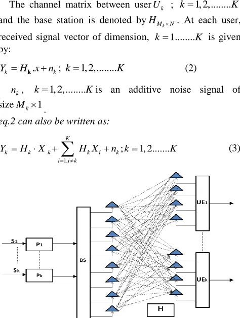
We are interested in modeling of the Link adaptive MIMO system with SVD precoding and full feedback. As given in paper [6] fig 1 shows a multiuser System, Let us assume that a base station has N numbers of antennas and sends signal to K number of users U U1, 2...Uk each of
the receiver equipped with M M1, 2...Mk
.antennas.
The transmitted signal matrix
x
N M k is expressed as thesum of signals intended to usersU U1, 2...Uk:
,
1 1
k M K
k l
k l
x X
(1)
The channel matrix between userUk ; k1, 2,...K
and the base station is denoted by
k
M N
H . At each user,
received signal vector of dimension, k1...K is given by:
.
k k
Y H x nk ; k1, 2,...K (2)
k
n , k1, 2,...Kis an additive noise signal of sizeMk1.
eq.2 can also be written as:
1,
; 1, 2... K
k k k k i k
i i k
Y H X H X n k K
[image:2.612.50.287.313.627.2]
(3)Fig 1: 8×8 multiuser MIMO system with 2 users each having 4 antennas
The second term of the sum in equation (3) represents the multiuser interference (MUI) coming from multiple users.
K
k i
i k
MUI H X
(4)
Block diagonalization using SVD removes the second term of the equations but it cannot remove interference among the antennas of the user itself. With help of Maximum ration transmission technique this interference also removes. Means MRT supports perfect beam forming which need perfect CSI information at transmitter. SVD is applied second time to remove inter antennas interference of the user itself.
A. MRT precoding technique with multiuser MIMO:
Let us define Hk( )j to be the interference channel matrix
of the jth antenna at the kth user:
,
( )
1 1 k j
j
k k
k
K
h
1 H
H H
H
H
(5)
Where H( )kj is thekth channel matrix that removed the
th
i line of
( )i
k
H can be expressed through SVD and
described by:
( )j ( )j ( )j j j
k k k
( )(1) ( )(0) k k
H U V V (6)
Where Vk( )(0)j Þ is the right-singular matrix with zero
singular value and Vk( )(1)j is the right-singular matrix with
non-zero singular value. Therefore, Vk( )(0)j is the zero space
ofH( )kj . For the kthuser, Maximum ratio transmission
precoding is given by:
( )
(1) (2)
[ , , Mk ]
k k k k
F F F F (7)
The total number of the receiver antennas isMk, the
new precoding matrix of the jthreceiver antenna at the kth
user (M dimension column) denotes ( )j ( )(0)j ( )
k k k
F V M ,
and Fk is the precoding matrix for the th
k user
MkN) dimension.International Journal of Emerging Technology and Advanced Engineering
Website: www.ijetae.com (ISSN 2250-2459, ISO 9001:2008 Certified Journal, Volume 8, Issue 1, January 2018)
106
Further, the receiver vector at userk is written as:
( ) ( )
, 1, , 1,
M K
Mk k j
y h F x h F x H F xi n k k Mk k j j M k Mk k i i k k k k
k
(8)
k kx nk (9)
In equations (14) and (15) the first part is the coefficient
of the receiver antenna at userk, , ( k)
k M
k hk M F
(Mkisthe dimension column of precoder matrix F), the second part is interference from other antennas of user k which
becomes zero, as , ( j)
k M
k M k
h F x is zero if jMk . The third
part is MUI, and H Fk kis zero obviously for ik.
The received symbol at each antenna at user k is written as:
( )i k( )i
k( )i
' k
y y (10)
III. QUANTIZATION OF RECEIVED SIGNAL
Equation (10) can be rewritten after quantization by uniform quantizer as
( , , , )
k
k k k
y Qk M xk M nk M
(11)
(1 ) (1 )
, , ,
b b Q
k
k k k
y x n n
k M k M k M
(12)
Where real and quadrature component of signal are separately quantized and
2
4 ADC precision[3].
k k
b
k
E y y
for b bit E y (13)
The normalized mean squared error and nQ
is the quantization noise with variance
(14)
2
2
, ,
(1 ) k t k
b b k M n M
k
P KM
(15)
The signal to quantization noise ratio is given by
2
2 2
, ,
2 2 2 2
,
,
(1 ) (1 )
(1 ) 1
k
k k
k
k k
t
b k M b k M M
k
b n M Q
b k M M
P KM SQNR
(16)
IV. SUM RATE CAPACITY FOR MRTPRECODING WITH
FULL CSIT
Assuming that the noise nQ follows the worst-case
Gaussian distribution, the average achievable rate with
perfect CSIT and conjugate beam forming is for Mk
antenna of a user k is
2 ,
, , 2 2
,
(1 )
( , ) log 1
1
k k
k k
k k
b k M M
MU MIMO M k M
b k M M
h
R b E
h
(17)
According to the paper [4]
2
, k
k M t
h N
Hence,
, 2
(1 )
( , ) log 1
1
k k
k
b t M
MU MIMO M
b t M
N R b N
if channel
is IID Rayleigh fading channel. (18)
The average achievable rate with perfect CSIT is approximately,
2 , ,
,
2 ,
log 1 (1 ) f low SNR
( , ) 1
log for large SNR
k k
k
k
b k M t k M
MU MIMO M
k M b N or R b
(19)
For K users having M k antennas sum rate capacity with
perfect CSIT is given by
2 , ,
1 1
( , ) log 1 (1 ) f low
k
k M
K
MU MIMO b k l t k M
k l
R b N or
(20) 2 , , , 1 1 1( , ) log f large
k
k M
K
MU MIMO k M
b k l
k l
R b or
(21) 2 2 (1 )Q b b yk
International Journal of Emerging Technology and Advanced Engineering
Website: www.ijetae.com (ISSN 2250-2459, ISO 9001:2008 Certified Journal, Volume 8, Issue 1, January 2018)
107
V. SUM RATE CAPACITY FOR MRT PRECODING WITH
LIMITED FEEDBACK
Averaging over the RVQ codebooks, the achievable rate under B bit (limited) feedback for antenna Mk of user k is
2 ,
, 2 2
,
(1 )
log 1
1
k k
k
k k
b k M M
MU MIMO M
b k M M
R
22)
1
2
1
(1 ) 1 2
log 1
1 1 2
t k
t k
B N
b t M
B N
b M t
N
N
(23)
In the low and high SNR regimes, the average achievable rate with limited feedback for antenna Mk of
user k is
1
2 , ,
,
2 ,
log 1 (1 ) 1 2 f low
( , )
1
log for large
t
k k
k
k B
N
b k M t k M
MU MIMO M
k M b
N or
R b B
(24)
For K user having Mk antennas sum rate capacity (bps/Hz) for multiuser MIMO with B bit feedback is given by
,
1 ( , ) log 1 (1 ) 1 2
2 ,
1 1 f low k
MU MIMO k M
B M
K k Nt
R b B Nt
b k l
k l or
(25)
2 ,
, ,
1 1
1
( , ) log f large
k
k M
K
MU MIMO k M
b k l
k l
R b B or
(26)
Theoretical description of limited feedback:
In this paper, we consider MU-MIMO system. The transmitter is equipped with Nt antennas and the receiver is
equipped with Mk antennas. Before quantization of signal,
SVD is applied to signal received form each antenna of each receiver.
First SVD operation removes multiuser interference from the signal, while second SVD operation removes the interantenna interference of the user itself. Now, the system becomes simple SISO system for each of the antenna of each user. After that, there are two, b bit ADC that separately quantize the real and imaginary part of received signal for each antennas of the each user. Uniform quantization is applied to the signal [7]. As analysis given in paper [4] for MISO case, the same case is applicable to all antennas of MU-MIMO system user separately. The random vector quantization (RVQ) is used to quantize direction of channel h. Out of B bit B1 bits are used to
convey direction information. The code book
0,
1,
2, 2B1 1
w
v
v v
v
Where each of the quantization vector is independently chosen from the isotropic distribution of Grassmannian manifold as in [8]. Besides the channel direction information, the remaining bits B2 =B-B1 are used to
quantize the phase of the equivalent channel. If
, k
h
k M is representing channel matrix of Mk antenna
of user k. Finding out optimum choice of
k M
v
for thatantenna should be
2
,
, 2
: 1
,
(1 )
arg max 1
k k
k
k k
b k M M
k M v v
b k M M
v
(27)
Where , k ( k)
M
k hk M F
and precodingmatrix ( k) ,
k M
k M
F v as given in eq. (8) and (9). The
optimization problem is non-convex and very difficult to solve.
For the case of full CSIT, transmitter chooses the best beamforming in the set
w v, max
form the codebook. Incase of finite feedback the receiver compute the term (27) for the each antenna of the user and match it with
v
in codebook and feedback the index of best one.The paper [4] also prove that if E || h||2= Nt then it is
possible to maximize sum rate capacity of MISO system with full CSIT and if
1
|| * || (1 2 t )
B N t
E h v N
Then we can maximize the
International Journal of Emerging Technology and Advanced Engineering
Website: www.ijetae.com (ISSN 2250-2459, ISO 9001:2008 Certified Journal, Volume 8, Issue 1, January 2018)
108
Both of these conclusions are applicable to multiuser MIMO system also. Because, when proposed MRT technique is applied to MU-MIMO system, it converts each antenna of each user into a separate MISO system.
VI. SIMULATIONS &RESULTS
In simulation, we investigate the performance of proposed scheme of precoding with limited feedback for the case of multiuser MIMO system. The proposed scheme is compared with DPC and BD-ZF precoding schemes [2] with full CSIT multiuser MIMO. A spatially uncorrelated MIMO Rayleigh fading of wireless channel and the noise distributed complex Gaussian variables with zero mean and unit-variance are assumed. The modulation QPSK is applied on signal.
For simplicity, we consider number of antennas for the each user is same; the simulation is performed for three
configurations of antennas 8 × 4, 8 × 6 and 8 × 8. The 8 ×
4 multiuser MIMO system is simulated for two users; each
having two antennas. The 8 × 6 multiuser MIMO system is
simulated for two users; each having three antennas, while
the 8 × 6 multiuser MIMO system is simulated for two
users; each having four antennas. Sum rate capacity Vs SNR are plotted & compared with other precoding schemes to prove superiority of MRT algorithm with limited feedback at lower SNR.
0 5 10 15 20 25
0 10 20 30 40 50 60
S
u
m
r
a
te
ca
p
a
ci
ty
b
p
s/
H
z
SNR dB
[image:5.612.359.532.146.273.2]MRT with full CSIT MRT with 4 bit feedback MRT with 8 bit feedback MRT with 16 bit feedback MRT with 24 bit feedback MRT with 32 bit feedback MRT with no feedback
Fig 2: Sum rate capacity upper and lower bound for MRT precoding with feedback for 8×8 configuration with two users, each user has
four antennas.
0 5 10 15 20 25
0 5 10 15 20 25 30
SNR dB
S
u
m
R
a
te
C
a
p
a
c
it
y
b
p
s
/H
z
[image:5.612.359.530.323.443.2]MRT with Full CSIT MRT with 4 feedback MRT with 8 bit feedback MRT with 16 bit feedback MRT with 24 bit feedback MRT with 32 bit feedback MRT with No feeedback
Fig 3: Sum rate capacity upper and lower bound for MRT precoding with feedback for 8×4 configuration with two users, each user has two
antennas.
0 5 10 15 20 25
0 5 10 15 20 25 30 35 40 45
SNR db
S
u
m
R
a
te
C
a
p
a
c
it
y
b
p
s
/H
z
[image:5.612.86.254.453.586.2]MRT with full CSIT MRT with 4 bit feedback MRT with 8 bit feedback MRT with 16 bit feedback MRT with 24 bit feedback MRT with 32 bit feedback MRT with No feedback
Fig 4: Sum rate capacity upper and lower bound for MRT precoding with feedback for 8×6 configuration with two users, each user has
three antennas.
0 5 10 15 20 25
0 10 20 30 40 50 60
S
u
m
r
a
te
ca
p
a
ci
ty
b
p
s/
H
z
SNR dB
MRT with full CSIT MRT with 4 bit feedback MRT with 8 bit feedback MRT with 16 bit feedback MRT with 24 bit feedback MRT with 32 bit feedback MRT with no feedback DPC with full CSIT BD-ZF with full CSIT
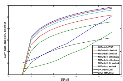
Fig 5: Sum rate capacity Vs SNR Curve for MU-MIMO system for various precoding and feedback schemes for 8×8 configuration with
[image:5.612.344.541.485.616.2]International Journal of Emerging Technology and Advanced Engineering
Website: www.ijetae.com (ISSN 2250-2459, ISO 9001:2008 Certified Journal, Volume 8, Issue 1, January 2018)
109
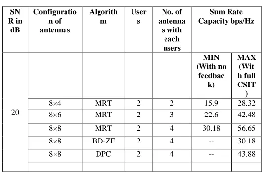
TABLEI
RESULTS OF SIMULATIONS
SN R in
dB
Configuratio n of antennas
Algorith m
User s
No. of antenna s with
each users
Sum Rate Capacity bps/Hz
20
MIN (With no
feedbac k)
MAX (Wit h full CSIT
)
8×4 MRT 2 2 15.9 28.32 8×6 MRT 2 3 22.6 42.48 8×8 MRT 2 4 30.18 56.65 8×8 BD-ZF 2 4 -- 30.18 8×8 DPC 2 4 -- 43.88
Figure 2, 3, 4, 5 and table 1 show the maximum and minimum sum rate capacity can be achieved with MRT precoding with feedback for multiuser MIMO system at different configuration of user and antennas. Maximum Sum rate capacity at 20 dB SNR is 56.65bps/Hz, while minimum sum rate capacity is 30.185bps/Hz with MRT precoding in 8×8 configuration (two users each with four antennas). If transmitter has more antennas then users antennas, the sum rate capacity reduces. For all configurations of system antennas, the sum rate capacity is increases with SNR in db. Also the sum rate capacity of BD-ZF and DPC precoding with full CSIT for 8×8 configuration (two users, each with four antennas) are laid below the sum rate capacity of MRT precoding with 4 bit feedback for 8×8 configuration (two users, each with four antennas) up to 20 db SNR. At higher SNR sum rate capacities of all precoding algorithm converges. Eq. (21) and (26) indicates the behavior of sum rate capacity at higher SNR.
VII. CONCLUSION
As explained in simulation and result, MRT precoding schemes with limited feedback results in a better performance of Multiuser MIMO system at lower SNR. The improved performance is resulted from beam forming of each of transmission stream of each user. Maximum Ratio transmission precoding scheme with limited feedback provide multiple benefits of providing good sum rate capacity while saving of uplink resources at lower SNR. At Higher SNR, it saves valuable uplink resource and gives same capacity as MRT with full CSIT.
REFERENCES
[1] E. Visotsky and U. Madhow, ―Space-time transmit precoding with imperfect feedback,‖ IEEE Transactions on Information Theory, vol. 47, no. 6, pp. 2632–2639, 2001.
[2] Sukriti Garg, Krati Mittal, Divyang Rawal, Dec 2015, ―Improved Signal Detection for Multiuser MIMO System using BD QR-LRL‖, in proceedings of IEEE conference on Computers and Devices for Communication (CODEC),Institute of Radio Physics & Electronics, University of Calcutta.
[3] J. Mo and R. W. Heath Jr., 2015, ―Limited feedback in multiple-antenna systems with one-bit quantization,‖ in proceeding of Asilomar conference on Signals, Systems and Computers, pp. 1432– 1436.
[4] ] J. Mo and R. W. Heath Jr. 2016, ―Limited feedback in MISO systems with finite-bit ADCs,‖ in proceedings of Asilomar Conference on Signals, Systems and Computers, pp. 479–483. [5] J. Mo and Robert W. Heath. 14 April 2017, ―Limited Feedback in
Single and Multi-user MIMO Systems with Finite-Bit ADCs‖, IEEE transition on wireless communication.
[6] Ben Zid Maha, Raoof Kosai, ―Recent Trends in Multi-user MIMO Communications‖, In Tech, Ch. 1, December 04, 2013, pp. 10-13. [7] J. Max, ―Quantizing for minimum distortion,‖ IRE Transactions on
Information Theory, vol. 6, no. 1, pp. 7–12, 1960.
[image:6.612.34.302.153.328.2]