International Journal of Emerging Technology and Advanced Engineering
Website: www.ijetae.com (ISSN 2250-2459, ISO 9001:2008 Certified Journal, Volume 9, Issue 5, May 2019)
122
An Analytical Study on Behaviour of Different Type of Shell
Structures
Badi Peter Seioshanseian
1, J.Sushmanth
2, N. Sai Kalyan
3, Mili
4, Jovian D’souza
5, Dr. Kiran Kamath
61,2,3,4,5
4th Year B.Tech, Civil Engineering, Manipal Institute of Technology, Manipal-576104 6
Professor, Civil Engineering Department, Manipal Institute of Technology, Manipal-576104
Abstract— This paper presents an understanding of the behavior of shell structures based on the parameters of relative rise where rise h (3-5m) varies with width W of the shell structure, h/W and varied plate thicknesses (0.1-0.35m)with the response of the structure to gravity loads (live and dead loads) and seismic loads as per IS code. Thin shells are an example of strength through form as opposed to strength through mass thus the main criteria for achieving higher strength in the shell structures was its geometry and the quantity of material used for its construction, therefore a constant cross-section is considered for the various shell structures that are being studied. The shell structures are modeled and analyzed by finite element method using a commercially available STAAD.Pro. Various graphs were plotted and studied from which the elliptical paraboloid shell structure was found to be the most optimum design.
Keywords— Shell Structure; STAAD.Pro; Cylindrical Shell; Elliptic Paraboloid Shell; Hyperbolic Paraboloid Shell; Axial Stress; Shear Stress; Bending Moments.
I. INTRODUCTION
The thin-shell structures, undulating and spanning good distances in dramatic cantilevers, clearly expresses strength and elegance in all their varied geometric forms. These thin-shells are designed to be able to carry the maximum live load, therefore it is required to decrease the self-weight of the structure as much as possible and thus function as a membrane free from large bending stresses. Due to the membrane action developed on the surface of thin-shells, it permits the structure to carry high loads while as beams and plates carry the loads by bending action. The membrane action is a general state of stress where there are only in-plane normal and shear stress resultants. Therefore shell structures are more efficient when compared to beams, columns or any other structural forms. Thus shells eliminate the need for columns and its bulky foundations leading to a column-free space and aesthetically attractive structure. This issue is of more importance in regions with high seismic activity as all the seismic forces are directly proportional to the mass of the structure. As a result, the main part of the shell structures are placed in pure compression.
Tim Michiels, & Sigrid Adriaenssens [4] investigated singly curved and doubly-curved shells with different spans and analyzed how these formal changes affect the fundamental frequencies as well as deformations and stresses for a code-based design input derived from the American Society of Civil Engineers code (A.S.C.E.-7). The authors reported that doubly-curved shells were found to perform far better than singly-curved shells as their geometric stiffness is much higher. Matteo Guidia et al. [6] studied a family of axisymmetric shells of revolution with variable curvature. The authors reported that the natural frequency increases with the curvature and is approximated by a linear function of the characteristic ratio c/R of the height of the pole to the radius of the plane projection of each shell of the family.
During the analysis of a shell structure, it is regarded as homogeneous and isotropic. However, in the design of the reinforcement, it is assumed that the concrete will be cracking and that the steel is provided to take care of the full direct and diagonal tension. The secret of avoiding cracks in such shells lies in the provision of closely spaced small diameter reinforcement that also imparts greater ductility to the structure. These reinforcements are then embedded in a rich mortar to build up the required thickness of the shell. By having less thickness, shell structures are able to span over large areas. This is due to their form based structural behaviour which leads to a minimum usage of construction materials thus making the thin-shell structures popular. The pure mathematics, boundary conditions and sort of loading dictate the way they transfer load or the way they fail. An advantage of shell structure is that one can design the shell structure as possibly thin even when loads that disrupt its characteristic membrane behaviour. Shell structure will confine this disturbance inside regions which may be optimized on an individual basis.
International Journal of Emerging Technology and Advanced Engineering
Website: www.ijetae.com (ISSN 2250-2459, ISO 9001:2008 Certified Journal, Volume 9, Issue 5, May 2019)
123
A thin shell structure is a shell with a thickness relatively small compared with its other dimensions. But it should not be so thin that deformations would be large compared with the thickness. A geometrically thin shell is a shell structure made with thickness made smaller compared to the radius of curvature of the mid-surface. Shell structures. Thin shell structures acquire their strength through forms rather than mass and have the ability to span large distances in a structurally efficient way.II. METHODS INCORPORATED
To accomplish a systematic flow of data and reduce time spent on tedious mathematical methods which are used to analyze different shell structures an effort is taken in the direction of Finite Element Modeling through which this process can be fast-forwarded and any desired set of results can be extracted. In this research, we consider three different types of shell structures namely Cylindrical Shells, Elliptical Paraboloid shell and Hyperbolic Paraboloid shell considered in a constant area of 150 m2. In order to analyze the following shells, we make the use of STAAD.Pro a FEM based software.
In general, the span of any contemporary shell structure should be less than 30m, hence while considering the shell designs we have taken a span of 15m and a width of 10m which is covered with a single span long shell. The design methodology incorporated in this research is a limit state design that conforms to the Indian Standard Code. To accomplish the following task we made use of the software STAAD.Pro which is a FEM based software. A three-step process was incorporated to be able to accomplish our task. The first step involves ‘modeling' which includes generating the geometrical layout of the shell structure that is drawn in AutoCAD initially and then exported to STAAD.PRO. The layout of the arch drawn was divided into 10 parts in order to draw plate elements, each of which had a length of 1.5m. In order to develop the FEM model, quadrilateral meshing of 3 by 3 divisions was done for each plate for cylindrical shell structures. For elliptic and hyperbolic paraboloid to generate geometry and meshing, a basic code was used in STAAD editor. These shell structures were meshed by 10 x 10 divisions as quadrilateral meshing.
The second step is defining the cross-section of the structure and its material properties. A cross section of 1m by 0.5m for the edge beams and 0.6m by 0.3m for the arch beams is provided for cylindrical shells. Constant material properties for M30 concrete is assigned to all shell structures.
To keep the data uniform across the three different types of shells, five different types of rises ranging from 3m to 5m with a 0.5m increment were considered. For each rise, six shell thickness between 0.1m to 0.35m with an increment of 0.05m was used. Lastly, we assigned pinned supports to all the three types of shells at four corners.
The last step is the loading process of the shell structures, three major loads of dead, live and seismic loads have been applied which were kept constant for all the shell structure types. Dead and live load were considered as 1 KN/m and the seismic loads were taken in two separate directions of X and Z for a structure considered in Mangalore, India.an ordinary moment resisting structure with response reduction factor as 3 and importance factor as 1 is taken. The soil type is considered hard soil and finally damping ratio taken as 0.05 %. All the loads considered conform to Indian Standard Code IS 875 (Part 1 to 5) & IS 1893-2002. Finally, the analysis is performed by software from which the results are extrapolated and then correlated with various parameters.
III. DEVELOPMENT OF ANUMERICAL DATABASE
The FEM model created was used to find numerical data from a collective of 84 graphs from which were found the Max Absolute stresses (N/mm2), Shear stresses given by SQX and SQY (N/mm2), Axial Stresses given by SX and SY (N/mm2) and Moments (KNm/m). The graph obtained has a relative rise taken on the X-axis and the axial/shear stresses or moments ratios on the Y-axis. This collective of graphs is then compressed by only considering the maximum and the minimum value from each of the following stresses given above in both X and Y direction.
Different curves with respective thickness show the variations of stresses and moments with respect to the relative rise in the graphs. In order to eliminate the units and for easier inference in the X and Y axis of our results the values of both the rise and the stresses obtained where made relative. The relative rise is calculated by dividing the rise with the width of the shell which remained constant throughout the different shells. The absolute max and the axial stress are divided by (0.4 x Fck) because we consider characteristic strength Fck corresponding to 0.2% strain and hence for a design it is considered as 0.67 times of the characteristic strength.
International Journal of Emerging Technology and Advanced Engineering
Website: www.ijetae.com (ISSN 2250-2459, ISO 9001:2008 Certified Journal, Volume 9, Issue 5, May 2019)
124
The moments are then divided by (Plastic Modulus x Modules of Rupture) as Moment of resistant of concrete is given by the formula MR = Z x 0.7 x √𝑓𝑐𝑘, Z is plastic section modulus = I/y, where I is moment of inertia and y is the distance from the neutral axis and Fck is the characteristic strength of the concrete.IV. RESULTS AND DISCUSSIONS
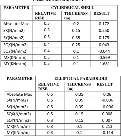
The most significant result obtained from the analysis of three major shell structures was the observation that the most optimum type of shell structure is an Elliptical Paraboloid shell which is categorized as a double curvature shell. The major results displayed by the three shell structures are represented in Tables 1 and 2.
After comparing the three shell structures for the maximum value of stress, Elliptical Paraboloid shell structure is found to be efficient in all the cases except SQX. In the case of SQX, we considered a Hyperbolic Paraboloid shell because it exhibits a lesser thickness.
TABLE1
COMBINED MINIMUM RESULTS
PARAMETER CYLINDRICAL SHELL
RELATIVE RISE
THICKENSS (m)
RESULT
Absolute Max 0.5 0.2 0.172
SX(N/mm2) 0.5 0.15 0.250
SY(N/mm2) 0.5 0.35 0.179
SQX(N/mm2) 0.4 0.25 0.043
SQY(N/mm2) 0.4 0.1 -0.044
MX(KNm/m) 0.5 0.1 -0.569
MY(KNm/m) 0.5 0.1 -1.681
After comparing three shell structures for the minimum value of stress, elliptical paraboloid shell is found to be the most efficient type of shell structure which also requires a lesser volume of concrete for the respective relative rise and thickness obtained by absolute maximum, axial stress, shear stress and moment per unit length. The study incorporates the use of a range of shell thickness from 0.1 m to 0.35m. In order to decipher wither the shell either a thin or thick shell, the thickness was divided by the radii of the shell structure. The observation was made on the bases that the result from the above is lesser than or greater than 0.05. It was observed that cylindrical shells with thickness 0.1, 0.15, 0.2 and 0.5 are found to be thin shells while thicknesses of 0.3 and 0.35 are found to be thick shells. This result will only vary in the shell with a relative rise of 0.5 where a thickness of 0.25 is also a thick shell. Use of the above results is to be able to differentiate the shells during their design phase.
TABLE 2
COMBINED MAXIMUM RESULTS
PARAMETER CYLINDRICAL SHELL
RELATIVE RISE
THICKENSS (m)
RESULT
Absolute Max 0.5 0.5 3.953
SX(N/mm2) 0.3 0.3 -2.025
SY(N/mm2) 0.5 0.5 1.756
SQX(N/mm2) 0.5 0.5 -0.0821
SQY(N/mm2) 0.5 0.5 0.245
MX(KNm/m) 0.3 0.3 17.607
MY(KNm/m) 0.5 0.5 57.034
PARAMETER ELLIPTICAL PARABOLOID
RELATIVE RISE
THICKENSS (m)
RESULT
Absolute Max 0.5 0.35 0.06
SX(N/mm2) 0.5 0.35 -0.006
SY(N/mm2) 0.5 0.35 -0.006
SQX(N/mm2) 0.5 0.15 0.008
SQY(N/mm2) 0.3 0.15 0.007
MX(KNm/m) 0.3 0.1 0.213
MY(KNm/m) 0.3 0.1 -0.114
PARAMETER HYPERBOLIC PARABOLIC
RELATIVE RISE
THICKENSS (m)
RESULT
Absolute Max 0.5 0.35 0.364
SX(N/mm2) 0.5 0.3 0.779
SY(N/mm2) 0.5 0.15 1.016
SQX(N/mm2) 0.3 0.1 -0.014
SQY(N/mm2) 0.45 0.1 -0.006
MX(KNm/m) 0.5 0.1 -0.661
[image:3.612.50.292.380.661.2]International Journal of Emerging Technology and Advanced Engineering
Website: www.ijetae.com (ISSN 2250-2459, ISO 9001:2008 Certified Journal, Volume 9, Issue 5, May 2019)
125
PARAMETER ELLIPTICAL PARABOLOID
RELATIVE RISE
THICKENSS (m)
RESULT
Absolute Max 0.45 0.35 1.678
SX(N/mm2) 0.45 0.35 -0.96
SY(N/mm2) 0.3 0.35 -0.4335
SQX(N/mm2) 0.3 0.35 -0.0238
SQY(N/mm2) 0.3 0.35 0.0213
MX(KNm/m) 0.45 0.35 8.269
MY(KNm/m) 0.3 0.35 5.74253
PARAMETER HYPERBOLIC PARABOLIC
RELATIVE RISE
THICKENSS (m)
RESULT
Absolute Max 0.35 0.25 4.836
SX(N/mm2) 0.5 0.1 3.12911
SY(N/mm2) 0.3 0.1 -1.8891
SQX(N/mm2) 0.3 0.35 0.06598
SQY(N/mm2) 0.3 0.35 0.0689
MX(KNm/m) 0.3 0.35 13.7075
MY(KNm/m) 0.3 0.35 -9.9956
In order to study the nature of the stresses caused on the surface, the regions of compression and tension were studied. It was observed that in both cylindrical and elliptical paraboloid shell maximum compression zone in the X direction was at the supports, while in a hyperbolic paraboloid shell it was observed that the supports present on the ground are in compression while the supports at a given relative rise wherein tension. The following results show the variation of compressive and tensile action in various zones of the three shells. By decreasing the thickness of the shell, we can reduce the volume of concrete used in designing of the shell structure.
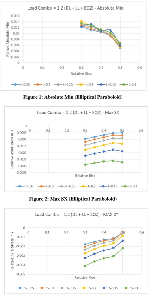
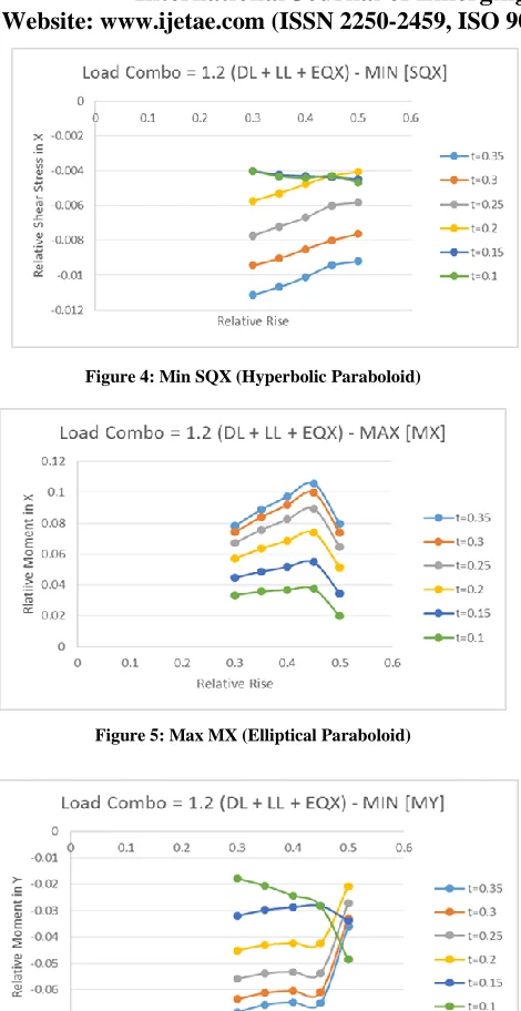
Absolute stresses (Figure 1) shows the minimum stress in the shell structure. This value is irrespective of the nature of stress as axial, shear, tension or compression. Therefore other parameters with specific stress are required for further detailed analysis of the shell. From the graphs (Figure 2) and (Figure 3) the axial stress in X and Y directions are uniformly decreasing with respect to the thickness as well as relative rise, inferring that the elliptical paraboloid with a thickness of 0.35m and a 5m rise is the optimum shell structure. The shear stress (Figure 4) generally decreases with the relative rise for thicker thickness but for 0.1m and 0.15m thickness it is almost constant and the lowest value is for a 3m rise and 0.1m thickness. The curves of the graph for MX (Figure 5) display the lowest value at a 4.5m rise.
[image:4.612.51.286.138.399.2]The moments along the Y direction (Figure 6) generally decrease with relative rise except for 0.1m and 0.15m were it increases.
Figure 1: Absolute Min (Elliptical Paraboloid)
[image:4.612.328.565.177.654.2]Figure 2: Max SX (Elliptical Paraboloid)
International Journal of Emerging Technology and Advanced Engineering
Website: www.ijetae.com (ISSN 2250-2459, ISO 9001:2008 Certified Journal, Volume 9, Issue 5, May 2019)
[image:5.612.54.289.116.572.2]126
Figure 4: Min SQX (Hyperbolic Paraboloid)Figure 5: Max MX (Elliptical Paraboloid)
Figure 6: Min MY (Elliptical Paraboloid)
V. CONCLUSION
In this research, three different types of shell structures are considered and compared namely cylindrical shell, hyperbolic paraboloid shell, and elliptical paraboloid shell.
In essence, this paper focuses to obtain the most efficient type of shell structure which is described by their plate thicknesses and rises, that is the shell structure using concrete economically. This is done by analyzing and then comparing the relative rise where rise h (3-5m) varies with width W of the shell structure, h/W and varied plate thicknesses (0.1-0.35m) of these respective types of shell structures. The Dead load, Live load and Earthquake loads are taken into consideration and were analyzed based on the results obtained. The values of the axial shear, shear stress and moment per unit length are taken into consideration and compared. Through the analysis, we found that elliptical paraboloid shell structure is the most optimum design as the stresses were found to be least when compared to the other studied shell structures.
REFERENCES
[1] Tamboli, N., & Kulkarni, A. B. (2014). Bending Analysis of Paraboloid of Revolution Shell. International Journal of Civil Engineering Research (India), 5, 307-314.
[2] Winterstetter, T. A., & Schmidt, H. (2002). Stability of circular cylindrical steel shells under combined loading. Thin-Walled Structures, 40(10), 893-910.
[3] Gomes, C., Parente, M., Azenha, M., & Lino, J. C. (2018). An integrated framework for multi-criteria optimization of thin concrete shells at early design stages. Advanced Engineering Informatics, 38, 330-342.
[4] Michiels, T., & Adriaenssens, S. (2017). Identification of key design parameters for earthquake resistance of reinforced concrete shell structures. Engineering Structures, 153, 411-420.
[5] Tamijani, A. Y., Hurley, J., & Gharibi, K. (2018). Determination of load paths in plates and shells. Thin-Walled Structures, 127, 646-653.
[6] Guidi, M., Fregolent, A., & Ruta, G. (2017). Curvature effects on the Eigen properties of axisymmetric thin shells. Thin-Walled Structures, 119, 224-234.
[7] Kulkarni, M. M. S., & Aliasgher, L. (2014). Analysis of Tensile Fabric Structure Using Thin Concrete Doubly Curved Shell. International Journal of Research in Advent Technology, 2(3), 156-165.
[8] Jin, H., Yu, K., Gong, Q., & Zhou, S. (2018). Load-carrying capability of shield tunnel damaged by shield shell squeezing action during construction. Thin-Walled Structures, 132, 69-78.
[9] Stavridis, L. T., & Armenakas, A. E. (1988). Analysis of shallow shells with rectangular projection: theory. Journal of engineering mechanics, 114(6), 923-942.
[10] Bosniakowski, S., & Bergmann, R. (1988). Analysis of continuous circular cylindrical shells. Journal of engineering mechanics, 114(3), 433-455.
International Journal of Emerging Technology and Advanced Engineering
Website: www.ijetae.com (ISSN 2250-2459, ISO 9001:2008 Certified Journal, Volume 9, Issue 5, May 2019)
127
[12] Gupta, P. K., & Gupta, N. K. (2018). A study of development mode of collapse with variation of strains and stresses during compression of metallic shells having dome-cone shape. Thin-Walled Structures, 126, 68-78.
[13] Fanous, F. S., Klaiber, F. W., & Wassef, W. G. (1996). Service load test of 1: 3 scale shell bridge model. Journal of Structural Engineering, 122(2), 210-216.
[14] Rajashekhar, M. R., & Ellingwood, B. R. (1995). Reliability of reinforced-concrete cylindrical shells. Journal of Structural Engineering, 121(2), 336-347.