International Journal of Emerging Technology and Advanced Engineering
Website: www.ijetae.com (ISSN 2250-2459,ISO 9001:2008 Certified Journal, Volume 4, Issue 9, September 2014)
533
A Study on Basic Water Cooling System of Gas Compressor
Engine
P. Praveen Babu
1, B. Siddeswara Rao
2, S. Jaya Kishore
3 1PG student, Thermal Engineering, Siddharth Institute of Engineering and Technology, Puttur-517583, India
2Associate professor, Mechanical Engineering, Siddharth Institute of Engineering and Technology, Puttur-517583, India 3Assistant professor, Mechanical Engineering, Siddartha Institute of Science and Technology, Puttur-517583, India
Abstract----Natural gas transmission industries confront engine problems at compressor stations, particularly maintaining proper cooling system for gas compressor engines of large bored. It is better to understand the heat transfer mechanisms from the combustion gases to the cooling water and then from the cooling water to the environment. To meet this need a logic tree is developed to provide guidance on how to balance and identify problems within cooling system and schedule appropriate maintenance. A cooling system model is developed to supplement the logic tree in providing further guidance and understanding of cooling system operation. Fluid dynamics, Thermodynamics and Heat transfer are involved in developing a cooling system model and the operation is familiar to the general operating companies. There will be the comparison and parametric investigation of the cooling system model in the logic tree and the results are summarized as tables and charts.
Keywords--- Natural Gas, Cooling system model,
MATLAB, Logic tree and Gas Compressor Engine.
I. INTRODUCTION
The focus of this thesis is to describe tasks and explain the physics of cooling system.
A. Objectives:
1. Combing information gathered from operating guides as well as the senior technicians from discussions about the operation of cooling system.
2. Prepare a document based on the information that how the cooling system should be operated at various loads. 3. Utilize the gathered information to develop new cooling
system.
B. Tasks:
1. Conducting literature reviews. 2. Analyzing cooling system model.
3. Visiting sites to gather information on cooling system. 4. Applying principles of Thermodynamics, Heat transfer
and Fluid dynamics.
5. Formulating equations to evaluate operating parameters of the cooling system.
6. Those equations are coded in the MATLAB.
Figure1.Pictorial representation of cooling system
1. Engine 2. Surge tank 3. Coolant pump
4. Fin- fan heat exchanger 5. Engine oil cooler
6. Thermostatic control valve
C. Energy transfer within the cooling system
Most of the energy transfers to the cooling system. The modes of heat transfer are convection and conduction.
Energy is added or removed is calculated by the principles of Thermodynamics and Heat transfer.
D. Fluid dynamics within coolant piping system
The coolant system consists of following components:
1. Piping 2. Fittings 3. Coolant pump 4. Surge Tank 5. Cooling Equipment
The resulting pressure in the pipe is affected by the change in height, number of fittings, and length and diameter of the pipe. so, that effect is calculated using fluid dynamics principles.
Pump head and coolant flow rate entirely depends upon pump speed, it in turn depends on engine speed.
International Journal of Emerging Technology and Advanced Engineering
Website: www.ijetae.com (ISSN 2250-2459,ISO 9001:2008 Certified Journal, Volume 4, Issue 9, September 2014)
534
Outlet pressure of the surge tank can be calculated by the fluid dynamic principles.The cooling equipment consists of engine, oil cooler and fin-fan unit. There is differential pressure at each component of the cooling system and this differential pressure is calculated by the fluid dynamic principles.
II. LITERATURE REVIEW
This section is focused on the cooling system designing considering in-cylinder to coolant heat transfer relations, incompressible fluid flow and various cooling system setups are presented.
A. Review of cooling system setups
1.A review was made on the diesel engine cooling system in the labs of university colleges.
2.A large bored diesel engine was reviewed at government hospitals.
B. Modeling the thermal system:
1.Various equations are derived from Thermodynamics, heat transfer and fluid dynamic principles.
2.First law of Thermodynamics and the conservation of mass provides a basis to build a thermal system. An example equation:
q - i(ii + (vi2/2) + gZi – e (ie + ve2 + gZe) = dE/dt
3.In this a review was made on the heat exchanger model i.e., How the heat energy transfers from hot fluid to metal and metal to the cold fluid.
C. Engine cylinder to coolant heat transfer
1.Most of the heat energy enters the coolant in the cooling system from the engine.
2.So, heat transfer coefficient is to be calculated for the engine on both in-cylinder and jacket water side. 3.Using first law of thermodynamics cylinder pressure
and temperature is calculated.
4.In-cylinder heat transfer coefficient is calculated with the help of Woschni’s equation:
Hgas = 3.26 B -0.2
P0.8T-0.55W0.8
W = C1Sp + C2[(VdTr)/(PrVr)]*(P-Pm)
5. The heat flux from the engine cylinder to jacket water can be calculated using thermal resistances.
For example: Robject = 1/hSubstance
D. Incompressible Fluid Flow
1.Crowe provide equations for the Head loss, friction factors, and dimensionless head loss coefficients for transitions and fittings.
2.Daily and Harleman explained the nonuniform flow conduits and Bernoulli’s equation pertaining to pipe flow.
3.Friction Factor:
f = 0.25/[log10((ks/3.7D) + (5.74/Re 0.9
)]2
4.Dimensionless Head loss coefficient: Hf = K(V12/2g)
5.Modified Bernoulli’s equation:
P1 + ρgz1 = P2 ρgz2 ρgHf
E. Conclusions for Literature Review
1. The Heat transfer from the combusting gases to cooling water was modeled using Thermal Resistances.
2. Woschni’s equation was used to determine the in-cylinder heat transfer coefficient.
3. The fluid dynamics of the cooling water system were modeled using modified Bernoulli’s equation.
4. The complete cooling water system modeling equations are coded in the MATLAB.
III. MATHEMATICAL DEVELOPMENT
This section focuses on the development of equations for the individual components using Heat transfer, Thermodynamics and fluid dynamics principles.
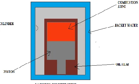
A. Cylinder to coolant heat transfer:
[image:2.612.327.567.561.707.2] The Heat transfer mechanism from the combustion area to the coolant flowing around the engine cylinder is illustrated here.
International Journal of Emerging Technology and Advanced Engineering
Website: www.ijetae.com (ISSN 2250-2459,ISO 9001:2008 Certified Journal, Volume 4, Issue 9, September 2014)
535
1. Resistance offered by the water jacketRjw= 1/hjw;
2. Resistance offered by the cylinder material(steel) Rsteel= x/Ksteel;
3. Resistance offered by the oil film Roil film= 1/hoil film;
4. Resistance offered by the combustion gases Rgas= 1/hgas;
5. Total resistance offered by entire structure Rtotal= Rjw+Rsteel+Roil film+Rgas
Therefore heat flux from the combustion zone to the water jacket can be calculated by the equation:
Heat flux = (Tgas-Tjw)/Rtotal
Where k is the thermal conductivity,
h is the convective heat transfer coefficient, and T is the temperature.
[image:3.612.326.569.252.562.2]B. Heat exchangers:
Figure .3 heat exchanger
The engine oil cooler and fin-fan unit are acts as heat exchangers, hence the mechanism of heat transfer and the following temperatures are:
1.Conduction and convection are primary modes of heat transfer.
2.For the inlet and outlet temperatures of Fin-fan unit both the convection and conduction formulae are used For example:
Q = mcp∆T; Q = hA∆T:
3.Where m is the mass flow rate, Cp is the specific heat,
∆T is the temperature difference.
The energy is transferred from hot fluid to the intermediate metal and then to the cooling fluid. The cooling water plays different roles within the fin-fan unit, engine oil cooler.
The cooling water acts as the hot fluid in the fin-fan unit and the energy is transferred to the ambient air. In the engine oil cooler, energy is transferred from the hot oil to the cooling water.
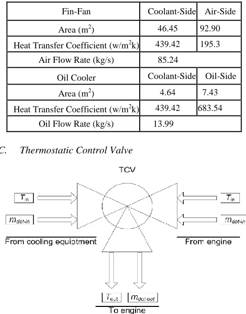
Due to the lack of available information regarding the heat exchangers, values were assumed for the heat transfer areas and the convective heat transfer coefficients.
TABLE 1.
ASSUMED HEAT EXCHANGER PARAMETERS
C. Thermostatic Control Valve
Figure .4 thermostatic control valve
The TCV is assumed to be a adiabatic mixing process with no changes in kinetic and potential energies, and constant specific heats. Applying the conditions of first law of thermodynamics, Equation is re-written as:
sysTsys rec Trec = eng,inTeng,in
Where,
= mass flow rate T = Temperature
Fin-Fan Coolant-Side Air-Side
Area (m2) 46.45 92.90
Heat Transfer Coefficient (w/m2k) 439.42 195.3
Air Flow Rate (kg/s) 85.24
Oil Cooler Coolant-Side Oil-Side
Area (m2) 4.64 7.43
Heat Transfer Coefficient (w/m2k) 439.42 683.54
[image:3.612.51.290.307.492.2]International Journal of Emerging Technology and Advanced Engineering
Website: www.ijetae.com (ISSN 2250-2459,ISO 9001:2008 Certified Journal, Volume 4, Issue 9, September 2014)
536
[image:4.612.48.282.133.280.2]D. Coolant Piping System
Figure .5 cooling system overview
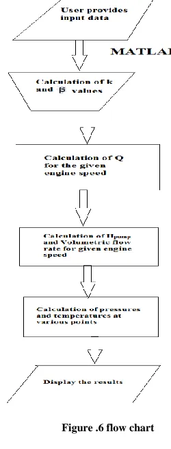
IV. MODEL DEVELOPMENT
Using those equations that which are developed in the above sections, describes the heat transfer, fluid dynamics, and thermodynamics were involved in the system.
These sets of equations were used to calculate:
1. Pressures at various points within the cooling system. Inlet and outlet temperatures of the cooling equipment. Mass flow rate of the recirculate coolant.
2. Mass flow rate within the system containing Finfan unit and oil cooler.
3. Heat transfer from water coolant to the ambient air and from oil to the water.
4. Heat flux from the in-cylinder to the cooling water jacket.
5. Pump head and volumetric flow at the pump. 6. Pressure loss coefficients related to the mass flow
[image:4.612.365.490.142.469.2]rate at finfan unit and oil cooler.
Figure .6 flow chart
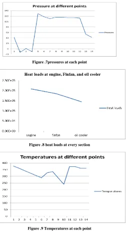
V. RESULTS AND DISCUSSION
International Journal of Emerging Technology and Advanced Engineering
Website: www.ijetae.com (ISSN 2250-2459,ISO 9001:2008 Certified Journal, Volume 4, Issue 9, September 2014)
[image:5.612.49.303.148.611.2]537
Graphs for the pressure, heat loads and temperatures:Figure .7pressures at each point
Figure .8 heat loads at every section
Figure .9 Temperatures at each point
VI. CONCLUSION
A logic chart was developed as part to assist operators in understanding cooling systems and finding possible problems within the cooling system. To supplement the logic chart, an engine cooling system modeling program has been developed for large bore engines. The model governing equations are based upon the fluid dynamics, thermodynamics, and heat transfer experienced within the cooling system.
The input parameters are familiar to the operators and include engine characteristics, piping system characteristics, ambient conditions, coolant chemistry, and engine oil system characteristics.
The recommendations for future work are:
1. In order to further validate the cooling system model, the model should be field tested against data collected throughout an entire system.
2. To get full use of the cooling system model, more instrumentation should be incorporated into cooling systems.
3. Since the pump head and flow rate are governed by the engine speed, the engine speed indicates the engine coolant inlet pressure and mass flow rate. 4. The model calculated values are within 10% of the
field collected data.
5. Used to properly size cooling system components. Tuned to fit actual cooling system data.
6. Used by operating companies to determine if the cooling equipment within the system is able to handle the heat loads experienced during daily operation. 7. The system model is able to analyze a cooling system
when the engine is not operating at full speed and as the engine ramps up to full speed.
REFERENCES
[1] K.S. Chapman. “The Enhancement and Validation of a Vehicle Engine Cooling System Simulation for Use as a Cooling System Design Tool,” M.S. thesis, ME, MTU, Houghton, MI, 1987. [2] K.S. Chapman, E. Chiang, and J.H. Johnson, “The Use of the
Vehicle Engine Cooling System Simulation as a Cooling System Design Tool,” SAE Congress and Symposium, 880600, Detroit, MI, 1988.
[3] B. J. Luptowski, O. Arici, J.H. Johnson, G.G. Parker, “Development of enhanced vehicle and engine cooling system simulation and application to active cooling control”. in SAE World Congress, pp. 197–210, Detroit, MI, USA, April 2005.
[4] K. Robinson, J.G. Hawley, N.A.F. Campbell, and D.G. Tilley, “A review of precision engine cooling,” in International Congress and Exposition, Detroit, Mich., 1999.
[5] W.M. Kays, “Heat transmission from the engine to the atmosphere,” Proceedings of the International Centre for Heat and Mass Transfer, pp. 333, 1989.
[6] M.J. Moran, H.N. Shapiro, Fundamentals of Engineering Thermodynamics, John Wiley, Hoboken, NJ 2007.
[7] W.F Stoecker. Design of Thermal Systems. New York: McGraw-Hill, 1989, pp. 80-152.
[8] S.V. Patankar, Numerical Heat Transfer and Fluid Flow, Hemisphere, Washington, D.C., 1980.