TM
Space-Time Memory: A Parallel Programming Abstraction for
Dynamic Vision Applications
James M. Rehg
Umakishore Ramachandran
Robert H. Halstead, Jr.
Christopher F. Joerg
Leonidas Kontothanassis
Rishiyur S. Nikhil
Sing Bing Kang
CRL 97/2
The Cambridge Research Laboratory was founded in 1987 to advance the state of the art in both core computing and human-computer interaction, and to use the knowledge so gained to support the Company’s corporate objectives. We believe this is best accomplished through interconnected pur-suits in technology creation, advanced systems engineering, and business development. We are ac-tively investigating scalable computing; mobile computing; vision-based human and scene sensing; speech interaction; computer-animated synthetic persona; intelligent information appliances; and the capture, coding, storage, indexing, retrieval, decoding, and rendering of multimedia data. We recognize and embrace a technology creation model which is characterized by three major phases:
Freedom: The life blood of the Laboratory comes from the observations and imaginations of our
research staff. It is here that challenging research problems are uncovered (through discussions with customers, through interactions with others in the Corporation, through other professional interac-tions, through reading, and the like) or that new ideas are born. For any such problem or idea, this phase culminates in the nucleation of a project team around a well articulated central research question and the outlining of a research plan.
Focus: Once a team is formed, we aggressively pursue the creation of new technology based on
the plan. This may involve direct collaboration with other technical professionals inside and outside the Corporation. This phase culminates in the demonstrable creation of new technology which may take any of a number of forms - a journal article, a technical talk, a working prototype, a patent application, or some combination of these. The research team is typically augmented with other resident professionals—engineering and business development—who work as integral members of the core team to prepare preliminary plans for how best to leverage this new knowledge, either through internal transfer of technology or through other means.
Follow-through: We actively pursue taking the best technologies to the marketplace. For those
opportunities which are not immediately transferred internally and where the team has identified a significant opportunity, the business development and engineering staff will lead early-stage com-mercial development, often in conjunction with members of the research staff. While the value to the Corporation of taking these new ideas to the market is clear, it also has a significant positive im-pact on our future research work by providing the means to understand intimately the problems and opportunities in the market and to more fully exercise our ideas and concepts in real-world settings.
Throughout this process, communicating our understanding is a critical part of what we do, and participating in the larger technical community—through the publication of refereed journal articles and the presentation of our ideas at conferences–is essential. Our technical report series supports and facilitates broad and early dissemination of our work. We welcome your feedback on its effec-tiveness.
Space-Time Memory: A Parallel Programming Abstraction
for Dynamic Vision Applications
James M. Rehg
Umakishore Ramachandran
Robert H. Halstead, Jr.
Christopher F. Joerg
Leonidas Kontothanassis
Rishiyur S. Nikhil
Sing Bing Kang
April 1, 1997
Abstract
Commercial MIMD computers promise cost-effective parallel processing for com-puter vision applications, but programming them is time-consuming and obtaining good performance is often difficult. We describe a class of vision applications which are well-suited to multi-threaded implementation on MIMD computers, using the ex-ample of a Smart Kiosk.
We present a novel parallel programming abstraction called Space-Time Memory (STM) which is designed to support the dynamic data and control flow requirements of multithreaded computer vision applications. The STM model provides high-level primitives for memory management and synchronization which simplify software de-velopment on MIMD computers.
Address for Ramachandran:
College of Computing, Georgia Institute of Technology, Atlanta GA 30332, USA. Email:[email protected]
Address for Halstead:
Curl Corporation, 4 Cambridge Center, 7th floor, Cambridge MA 02142, USA. Email:[email protected]
The work described in this report took place at the Cambridge Research Laboratory.
c Digital Equipment Corporation, 1997
This work may not be copied or reproduced in whole or in part for any commercial purpose. Per-mission to copy in whole or in part without payment of fee is granted for nonprofit educational and research purposes provided that all such whole or partial copies include the following: a notice that such copying is by permission of the Cambridge Research Laboratory of Digital Equipment Corpo-ration in Cambridge, Massachusetts; an acknowledgment of the authors and individual contributors to the work; and all applicable portions of the copyright notice. Copying, reproducing, or repub-lishing for any other purpose shall require a license with payment of fee to the Cambridge Research Laboratory. All rights reserved.
CRL Technical reports are available on the CRL’s web page at http://www.crl.research.digital.com.
1
1
Introduction
Many computer vision applications exhibit coarse grain parallelism that makes them well-suited to multi-threaded implementation on modern MIMD (Multiple Instruction Multiple Data) parallel computers. For example, in advanced user-interfaces based on vision and speech sensing [18, 26], streams of video and audio data are processed in an independent or loosely-coupled fashion, resulting in significant task level parallelism. Furthermore, for a single data stream such as video there are typically a variety of low-level processing tasks that can be performed independently.
A multithreaded programming model provides an effective way to exploit task level parallelism. In this approach, each task in the application is implemented as a thread, a sequential flow of control analogous to a conventional sequential program. Multi-ple threads execute concurrently, sharing the available CPU resources and exchanging data and control signals at well-defined points in their execution. The multithreaded programming model is supported by a wide variety of commercially-available MIMD computers, such as the DIGITAL1 AlphaServer 4100 and Silicon Graphics Origin 2000. These systems provide hardware shared memory support for communication be-tween threads and software support for scheduling thread execution on multiple CPU’s. Unfortunately, implementing a vision application as a multithreaded program is significantly more difficult than writing a conventional sequential program. The largest source of difficulty arises from managing the communication of information between threads and synchronizing their access to shared data. This is particularly true for applications that are highly interactive and dynamic, and process time-varying streams of data at multiple rates.
A vision-based user-interface, for example, might perform background subtraction and low-level feature tracking at video rates, while performing face detection and ob-ject recognition much less frequently. Furthermore, the desired performance and rate of processing may change during run-time depending upon the users’ actions and the sys-tem’s goals. For example, a task such as facial expression analysis could range from being the performance bottleneck to not being performed at all. These factors com-plicate low-level implementation issues such as the allocation and recycling of frame buffers and the synchronization of processing tasks. As we will see in more detail in Section 2, these issues have a significant impact on programming difficulty and serve as a practical barrier to the widespread use of parallel computing in these applications. This report describes a novel parallel programming abstraction called Space-Time
Memory (STM) which is designed to support the dynamic data and control flow
re-quirements of multithreaded computer vision applications. The STM model provides high-level primitives for memory management and synchronization which simplify software development on MIMD computers. Since the STM abstraction is architecture-independent, programs that use it have increased portability. In addition, implemen-tations of the STM can be tuned for a particular architecture, increasing application performance without the need for a separate application tuning step.
This report provides an introduction to the STM model and its API. It is targeted
1The following are trademarks of Digital Equipment Corporation: Alpha, AlphaServer, Memory
towards potential users of the abstraction. It does not assume in-depth knowledge of parallel programming on the part of the reader. The STM is a component of the
Stam-pede system for computing on clusters of parallel machines which is being developed at
the Cambridge Research Laboratory (CRL) of Digital Equipment Corporation. More information about Stampede and the implementation of the STM abstraction can be found in [19].
In Section 2 we describe the Smart Kiosk application which motivates our work. We explore some of the difficulties that arise in writing parallel vision code. We de-scribe the design and core functionality of the STM in Section 3. Section 4 presents the results from a series of experiments that demonstrate the performance of the STM on two vision tasks, color tracking and image-based rendering.
2
The Smart Kiosk: A Dynamic Vision Application
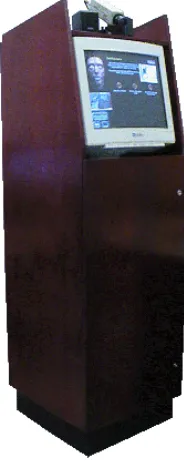
The design of the Space-Time Memory abstraction is motivated by the computational requirements of a class of dynamic, interactive computer vision applications. We in-troduce this class through a specific example: a vision-based user-interface for a Smart Kiosk [26]. A Smart Kiosk is a free-standing computerized device that is capable of interacting with multiple people in a public environment, providing information and entertainment.
[image:6.612.175.267.391.624.2]We are exploring a social interface paradigm for
Figure 1: The Smart Kiosk
kiosks. In this paradigm, vision and speech sensing provide user input while a graphical speaking agent provides the kiosk’s output. A description of the project, including results from a recent public instal-lation, can be found in [4]. A related kiosk applica-tion is described in [7].
Figure 1 shows a picture of our most recent Smart Kiosk prototype. The camera at the top of the de-vice acquires images of people standing in front of the kiosk display. The kiosk employs vision tech-niques to track and identify people based on their motion and clothing color [21]. The estimated po-sition of multiple users drives the behavior of an an-imated graphical face, called DECface [25], which occupies the upper left corner of the display.
2.1 Color-Based Tracking Example 3
There is currently a great deal of interest in vision- and speech-based user-interfaces (see the recent collections [5, 8]). We believe the Smart Kiosk to be representative of a broad class of emerging applications in surveillance, autonomous agents, and intelli-gent vehicles and rooms.
A key attribute of the Smart Kiosk application is the real-time processing and gener-ation of multimedia data. Video and speech processing combined with computer graph-ics rendering and speech synthesis are critical components of a human-centered style of interaction. The number and bandwidth of these data streams results in dramatic computational requirements for the kiosk application. However, there is significant task-level parallelism as a result of the loose coupling between data streams. This can be exploited to improve performance. Unfortunately the complex data sharing patterns between tasks in the application make the development of a parallel implementation challenging.
One source of complexity arises when tasks share streams of input data which they sample at different rates. For example, a figure tracking task may need to sample every frame in an image sequence in order to accurately estimate the motion of a particular user. A face recognition task, in contrast, could be run much less frequently. Differ-ences in these sampling rates complicate the recycling and management of the frame buffers that hold the video input data.
The dynamics of the set of tasks that make up the kiosk application is a second source of complexity. These dynamics are a direct result of the interactive nature of the application. A task such as face recognition, for example, is only performed if a user has been detected in the scene. Thus, whether a task in the application is active or not can depend upon the state of the external world and the inputs the system has received. This variability complicates frame buffer management. In particular, there is a question of which image frames in an input video sequence a newly-activated task should be allowed to see.
2.1
Color-Based Tracking Example
The Smart Kiosk application can be viewed as a dynamic collection of tasks that pro-cess streams of input data at different sampling rates. To explore this point further, we focus on a subpart of the Smart Kiosk application that tracks multiple people in an image sequence based on the color of their shirts.
Figure 2 shows the task graph for a color-based person tracking algorithm taken from [21]. It was used in our first Smart Kiosk prototype, which is described in [26]. It tracks multiple people in the vicinity of the kiosk by comparing each video frame against a set of previously defined histogram models of the users’ shirt colors. There are four distinct tasks: digitizer, change detection, histogram, and target detection, which are shown as elliptical nodes in the diagram. The inputs and outputs for these tasks are shown as rectangles. For example, the histogram task reads video frames and writes color histograms. The target detection task is based on a modified version of histogram intersection [24].
Frame
Change Detection
Histogram Model
Target Detection
Target Detection
Model 1 Location
Video
Location
Model 2 Model 1
Digitizer
Histogram
Motion Mask
[image:8.612.159.510.87.204.2]Model 2
Figure 2: Task graph for the color-based tracker. Ellipses denote tasks, implemented as threads. Rectangles denote channels which hold streams of data flowing between tasks.
acquired background image from this frame to produce a motion mask (b) showing the foreground objects. Similarly, the histogram task produces a histogram model (c) of the video frame (a). Figure (c) shows the red-green projection of a normalized RGB histogram. The target detection task compares the image histogram to a previously defined model histogram, resulting in a backprojection image. The sum of the two backprojection images from the two targets is shown in (d). Peaks in the backprojection image correspond to the detected positions of the two subjects (e).
Parallelism at both the task and the data level are visible in the diagram of Figure 2. Task parallelism arises when distinct tasks can be executed simultaneously. It is most obvious in the change detection and histogram tasks, which have no data dependencies and can therefore be performed in parallel. It is also present in the form of pipelining, where for example the histogram and target detection tasks can be performed simulta-neously on different frames of an image sequence.
Data parallelism occurs when a single task can be replicated over distributed data. The target detection task is data parallel, since it performs the same operation for each color model in the application. The search for a set of models can be performed in par-allel by multiple instances of the target detection task. For example, Figure 2 illustrates a parallel search for two models. Similarly, data parallelism at the pixel level can be exploited in many image processing tasks, such as change detection or histogram, by subdividing a single frame into regions and processing them in parallel. In designing a parallel implementation of the color tracker we could focus on task parallelism, data parallelism, or some combination of the two.
Applications such as the Smart Kiosk fit most naturally into a task parallel frame-work because they are composed of a heterogeneous mixture of relatively independent tasks such as computer graphics rendering, speech, and vision processing. In con-trast, it would be difficult to find a single data parallel framework that embraced such a broad range of data types and operations. The Space-Time Memory abstraction sup-ports a task level programming model. We will study the color tracker application from a task-oriented viewpoint in this section. The integration of data parallelism within the task parallel STM framework is addressed in [20].
2.1 Color-Based Tracking Example 5
(a) Video Frame
(b) Motion Mask (c) Histogram Model
[image:9.612.217.340.129.241.2](d) Backprojection Image (e) Model Locations
channel that supports communication between tasks. Channels can be viewed as sets of buffers for storing sequences of intermediate results. We will examine the complex-ity that arises in managing these buffers when different tasks access dynamic data at different sampling rates. These examples illustrate some of the difficulties that arise in programming vision applications on MIMD computer systems.
2.2
Sequential Implementation
The first program example we consider is a conventional sequential implementation of the color tracker. For simplicity we will restrict the search to a single model. The four tasks digitizer, change detection, histogram, and target detection must exchange three types of data: images, masks, and histograms. The following fragment of pseudocode implements the communication using three global variables,frame buf,mask buf, and
hist buf:
frame_buf = allocate_frame_buffer() mask_buf = allocate_frame_buffer() hist_buf = allocate_histogram_buffer() Begin loop
frame_buf digitize_frame()
mask_buf detect_change(frame_buf)
hist_buf histogram(frame_buf)
(x,y) = detect_target(frame_buf, mask_buf, hist_buf) ...
End Loop free(frame_buf) free(mask_buf) free(hist_buf)
The global variables point to allocated storage. The syntax roughly follows the C language [11], as does the meaning of the assignment operator=. The redirection
operator denotes a function placing its output into a previously allocated buffer. Function calls inside the inner loop implement the four tasks. The final output of the application is the(x,y)location of the detected target in the image (see Figure 3 (e)). This position is computed bydetect target()using the input image, motion mask, and image histogram. This function also uses a histogram model of the target, which is omitted for simplicity.
The performance of a particular implementation is constrained by the execution times of its tasks and their data dependencies. Table 4 shows the execution times for the four color tracker tasks in milliseconds. These times were obtained on a 400 MHz AlphaServer 4100. Each task was given the full resources of a single CPU.
2.3 Simple Parallel Implementation 7
Task Execution time
digitizer 33 ms
histogram 110 ms
change detection 160 ms
[image:11.612.203.355.124.190.2]target detection 280 ms
Figure 4: Execution times for the four tasks in the color tracker.
000000000000 000000000000 000000000000 000000000000 111111111111 111111111111 111111111111 111111111111 00000000000 00000000000 11111111111 11111111111 00 00 11 11 00000 00000 00000 00000 11111 11111 11111 11111 000000000000 000000000000 111111111111 111111111111 00 00 11 11 000 000 111 111 0000000000000 0000000000000 0000000000000 0000000000000 1111111111111 1111111111111 1111111111111 1111111111111 Application Period ...
Target Detection Task
Histogram Task Change Detection Task
Digitizer Task (a) Sequential 000000000000 000000000000 000000000000 000000000000 000000000000 111111111111 111111111111 111111111111 111111111111 111111111111 000 000 111 111 000000000000 000000000000 000000000000 111111111111 111111111111 111111111111 0000000000000 0000000000000 0000000000000 0000000000000 0000000000000 1111111111111 1111111111111 1111111111111 1111111111111 1111111111111 000000000000 000000000000 000000000000 000000000000 000000000000 111111111111 111111111111 111111111111 111111111111 111111111111 000 000 111 111 000 000 111 111 Histogram Task 00000000000 00000000000 00000000000 11111111111 11111111111 11111111111 00 00 00 11 11 11 Digitizer Task: Wait() Period
Change Detection Task:
Application Period
...
...
...
...
Target Detection Task:
(b) Parallel
Figure 5: Time-line for sequential and parallel implementations of the color tracker. The throughput and latency is improved in (b) through pipelining and task parallelism.
2.3
Simple Parallel Implementation
We now consider the situation where the digitizer, histogram, change detection, and
target detection tasks are implemented as separate threads running on different
proces-sors in a parallel computer with shared memory. In this situation there is an opportunity to improve performance by exploiting task parallelism. By overlapping the execution of the tasks we can ensure that the slowest task, target detection, is never waiting for input data.
The time-line for the simple parallel solution is illustrated in Figure 5 (b). The application period now equals the execution time of the slowest task, as opposed to the sum over all of the tasks. This represents an improvement in the throughput of the application due to pipeline parallelism. Note that the latency2 is also improved as a
[image:11.612.117.440.231.447.2]result of performing the change detection and histogram tasks in parallel.
An implementation of the parallel solution depicted in Figure 5 (b) requires two departures from the sequential approach. First, each task becomes a separate thread which must perform mutual exclusion [3] when accessing shared variables to ensure the correctness of the application. We assume the use of a standard thread model such as POSIX [13].
The second departure is an increase in the complexity of buffer management. Dur-ing pipelinDur-ing a task has to buffer both the data item it is currently producDur-ing and any older items which are being processed in parallel by other tasks. For example, the over-lap between the digitizer and target detection tasks in Figure (b) means that two con-secutive video frames will need to be buffered at all times. The following pseudocode implements the buffer management strategy for the digitizer and target detection tasks:
digitizer task
...
Begin Loop i = 1..2
frame_buf = allocate_frame_buffer() enq(reverse_q, frame_buf)
End Loop Begin Loop
frame_buf = deq(reverse_q)
frame_buf digitize_frame()
enq(forward_q, frame_buf) wait()
End Loop
target detection task
Begin Loop ...
frame_buf = deq(forward_q)
(x,y) = detect_target(frame_buf, mask_buf, ...) enq(reverse_q, frame_buf)
... End Loop
Begin Loop i = 1..2
frame_buf = deq(reverse_q) free(frame_buf)
End Loop ...
Here we are using a standard bounded queue abstraction to handle the recycling of frame buffers between the two threads. The operationsenq()anddeq() denote
enqueue and dequeue operations, respectively. These routines can be easily designed to implement mutual exclusion (see [3]). Thewait()function delays the digitizer task
by the amount shown in the diagram, to avoid performing unnecessary work. The execution of other three tasks can be regulated solely by the availability of their inputs.
2.4 Complex Parallel Implementation 9
In this case, we initialize thereverse qwith two buffers that will hold the current
and previous digitized frames. When no buffers are available, the call to deqwill
block. All of the synchronization is hidden in the standardenq()anddeq()routines.
This example is a two buffer version of the standard producer-consumer problem.
2.4
Complex Parallel Implementation
A realistic vision application will exhibit considerably more complex data sharing pat-terns than the simple example above. In particular, there will be multiple producers and consumers per channel and more complicated access patterns. The bounded queue abstraction works well in the simple case where every data item is read by exactly one of possibly many consumers. Its extension to an application scenario like the Smart Kiosk is complicated by three factors:
The number of tasks that will share the data items in a given channel can vary during execution. For example, a video frame may be read by the change
detec-tion task, the histogram task, and zero or more target detecdetec-tion tasks, where the
exact number depends on the kiosk environment. The rate of execution of these tasks, which determines the rate at which they sample their input data, can also vary.
Multiple consumers can request the same data item, making a simple queue in-appropriate.
Items may be read and written out of order (i.e., a task may request a specific video frame which is different from the last one produced). Consumers may also want to skip over certain data items in a sequence, and different consumers may want to skip different items.
A secondary complicating issue is that in a cluster setting we cannot depend on the availability of transparent shared memory. Part of the simplicity of the earlier pseudocode implementations stemmed from the fact that shared variables were trans-parently accessible to threads (i.e., without requiring any additional operations). This is true for threads running on a single SMP with hardware shared memory. But com-munications between SMP’s require a different communication mechanism, such as message-passing, and involve communication delays of a different order of magnitude. Addressing these issues at the application level will dramatically increase the complex-ity of the code over our simple example and reduce its portabilcomplex-ity to other hardware platforms.
2.5
Summary
Dynamic vision applications such as the Smart Kiosk have four defining characteristics:
The set of tasks is dynamic due to the interactive nature of the application. Tasks can be created and suspended during program execution. The rate at which a task processes input data or generates output data can also change as a function of the system state.
The set of tasks is heterogeneous. Speech, vision, and rendering algorithms all contribute to the Smart Kiosk application. Even within a single data type such as video the task set can still be quite diverse.
The target hardware platform can also be heterogeneous, involving machines from multiple vendors linked by a variety of interconnects. We are particularly interested in networked clusters of SMP’s such as the DIGITAL AlphaServer 4100.
Implementing such dynamic vision applications on a cluster involves nontrivial parallel programming issues. Addressing these issues at the application level will be time-consuming and will result in complex nonportable code. A better solution is to use a high-level programming model which provides the necessary infrastructure and encapsulates it apart from the application. Unfortunately, commonly-available libraries and run-time systems for parallel systems do not provide adequate primitives for the complex data sharing needs of these dynamic applications. We have developed the Space-Time Memory abstraction to address these needs.
3
Space-Time Memory Abstraction
Space-Time Memory provides a mechanism for sharing time-varying data between threads in a parallel program. A basic element in the model is a channel, which holds a single stream of data and supports read and write accesses by multiple threads. In the color-based tracker (see Figure 2) there are five channels which provide storage for digitized frames, motion masks, histogram models, and output records from the two
target detection threads. Note that each thread writes its results to a channel, and all
threads except for digitizer read input data from one or more channels.
Each channel holds an ordered sequence of data items indexed by virtual time, an application-dependent measure of computational progress. Data items can be of arbitrary size and structure. Each item has an associated time-stamp, which gives its location within the channel. In the color tracker, progress is measured in video frames, and so the virtual time for the application is frame numbers. In other applications, virtual time might correspond to a sequence of mouse events, or indices in an iteration space.
11 Histogram Model 160 ms 110 ms Model 1 Location 00 00 00 00 11 11 11 11 00 00 00 00 11 11 11 11 00 00 00 11 11 11 000 000 000 111 111 111 00 00 00 11 11 11 00 00 00 11 11 11 00 00 00 11 11 11 000 000 000 111 111 111 00 00 00 11 11 11 000 000 000 111 111 111 000 000 000 111 111 111 00 00 00 11 11 11 00 00 00 11 11 11 000 000 000 111 111 111 00 00 00 11 11 11 00 00 00 11 11 11 00 00 00 11 11 11 00 00 00 00 11 11 11 11
Frame 000000
000 111 111 111 00 00 00 11 11 11 00 00 00 11 11 11 00 00 00 00 11 11 11 11 00 00 00 00 11 11 11 11 000 000 000 111 111 111 000 000 000 111 111 111 00 00 00 11 11 11 00 00 00 11 11 11 000 000 000 111 111 111 000 000 000 000 111 111 111 111 00 00 00 11 11 11 00 00 00 11 11 11 Video 00 00 00 11 11 11 24 000 000 000 111 111 111 00 00 00 00 11 11 11 11 00 00 00 00 11 11 11 11 00 00 00 00 11 11 11 11 000 000 000 000 111 111 111 111 000 000 000 111 111 111 000 000 000 111 111 111 000 000 000 111 111 111 000 000 000 111 111 111 00 00 00 11 11 11 00 00 00 11 11 11 00 00 00 11 11 11 00 00 00 11 11 11 33 ms Virtual Time 4 3 2 1 5
0 6 7 8 9 10 11
Motion Mask Model 2 Location Space 280 ms 280 ms
[image:15.612.118.433.124.300.2]12 13 14 15 16 17 18 19 20 21 22 23
Figure 6: Space-Time Memory array for the channels in the color-based tracker of Figure 2. Cells in the array which contain data items are shaded.
A thread must attach to a channel before it can read or write time-stamped data items. When a thread no longer needs a particular channel it can detach from it. These operations are analogous to opening and closing a file. Any thread in the application can attach to or detach from any channel at any time. Support for dynamic attachment and detachment is important since threads in the application may not always be active. When the STM is used in a cluster setting, it provides location-independent access. Threads can attach to channels regardless of which node they are currently running on. The organization of channels within the STM can be viewed as a two dimensional dynamic, concurrent data structure. This is illustrated in Figure 6, which shows a simu-lation of the contents of the STM during the execution of the color tracker application. The virtual time dimension runs across the top and the space dimension, correspond-ing to the channels, runs down the side. Threads access shared data at a location in the table by specifying a (channel, time-stamp) pair. The sparseness of the data items in the figure reflects the different sampling rates at which the threads process their inputs. Data dependencies between threads in the color tracker are easily visible in the figure as a result of time-stamp inheritance. All of the time-stamps used in the color tracker are produced by the digitizer thread, which initiates the computation. All other threads write output data items using time-stamps obtained from their inputs. This results in a temporal alignment of occupied cells in the STM for input video frames that pass completely through the application. There are four examples of this in the figure, corresponding to frames 0, 4, 14, and 23.
00000000000 00000000000 00000000000 00000000000 11111111111 11111111111 11111111111 11111111111 00 00 00 00 11 11 11 11 000000 000000 000000 000000 111111 111111 111111 111111 00000 00000 00000 00000 11111 11111 11111 11111 00 00 00 11 11 11 Model 1 Location 110 ms 160 ms 280 ms 00 00 00 11 11 11 00 00 00 11 11 11 00 00 00 11 11 11 00 00 00 11 11 11 00 00 00 11 11 11 00 00 00 11 11 11 00 00 00 11 11 11 Video 00 00 00 11 11 11 Histogram Task Frame 00 00 00 11 11 11 00 00 00 11 11 11 Motion Mask 00 00 00 11 11 11 00 00 00 11 11 11 Histogram Model
Target Detection Task
7 8 9 10 1112131415 16 17 18 19 20 Virtual Time
... 21 ...
33 ms
[image:16.612.168.494.105.369.2]Change Detection Task Digitizer Task
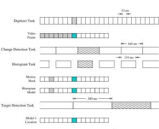
Figure 7: Effect of timing and data dependencies in determining which items are pro-cessed is illustrated for time-stamp 14 in Figure 6. The cross-hatched periods are the ones involved in processing item 14.
runs at its maximum rate, given by the timing data in Table 4. The exception is the
histogram thread which, for simplicity, is delayed so that its execution rate matches change detection. Each task selects the most recent data item from its input channel
at the start of its computation. This selection process is illustrated in the figure. Each channel is shown in its configuration prior to the start of the shaded interval in which time-stamp 14 is read. The question of which cells in the STM will be occupied is determined by the execution rates of the threads and their data dependencies.
All of the other tasks in the application are dependent upon the digitizer task for input data. As a result, the task period for the digitizer defines a natural “unit of real time” for the application. Virtual time provides a powerful abstraction of this conven-tional notion of a real-time period. For example, if the CPU clock rate doubled, the task execution times in the application would all shrink by one half. The treatment of time-stamps in an STM-based implementation, however, would be unaffected. The application would execute at its new rate, and the run-time system would manage the new pattern of data items in the STM transparently to the application.
13
during execution. Third, channels can be dynamically created and destroyed. Finally, tasks can attach to and detach from channels as needed.
There are two properties of channels in the STM that distinguish them from con-ventional dynamic data structures such as variable length arrays. First, channels com-bine both data storage and synchronization functions in a single primitive, providing a communication substrate for threads in the application. For example, threads that wish to retrieve a time-stamped item from a channel can arrange to be blocked until the item becomes available. This joint functionality is quite convenient. In this respect, channels can be viewed as a generalization of the bounded queue abstraction used in Section 2.3.
The second key property is the flexibility channels provide in reading and writing data items. Threads can read and write data at any sampling rate, and this sampling rate can vary over the course of their execution. Threads can also read and write items out of order. As a result of this flexibility, threads are free to run at arbitrary rates while the STM guarantees the correct buffering and recycling of data. This is especially impor-tant in applications like the Smart Kiosk where the computational resources assigned to a thread may change significantly as a function of the world state.
The design of an abstraction such as the STM involves a trade-off between the flexibility and convenience that application programmers desire and the practical con-siderations of its implementation. For example, some restrictions must necessarily be placed on the application’s ability to read and write data items. If threads are allowed to request data items that arrived arbitrarily far back in time, the available system memory would rapidly be exhausted by the accumulation of video frames.
There are two restrictions on reading and writing channel items in the STM which ensure that garbage collection can occur. The first is the write-once nature of data items: Once an item with a particular time-stamp has been written, it cannot be modified. It can be read an arbitrary number of times and will be garbage collected when it is no longer needed. The write-once property ensures that a thread never has to read a particular stamped item more than once. A second implication is that time-stamps whose data has been garbage collected need not be supported by the STM. This property is consistent with the dynamic nature of data in the STM. For example, a given video frame will not change once it has been digitized, but a new frame will be produced every 33 ms.
The second restriction is that threads cannot write channel items at arbitrary time-stamps, but are restricted to a range of legal values. This range is defined by the virtual
time lower bound (VTLB), which gives the smallest time-stamp to which a thread may
write an item. The abstraction ensures that the VTLB advances as threads process data. This makes garbage collection feasible, since it ensures that any given time-stamped item will eventually pass out of the representation. The VTLB and its relation to garbage collection are discussed further in Section 3.2.
3.1
Space-Time Memory API
We will introduce the application programming interface (API) for the STM through pseudocode examples for the digitizer and target detection threads. In these examples we focus on the use of the STM API to communicate data between tasks. There are five entities that make up the core of the STM abstraction: channels, connections, items, time-stamps, and virtual time. The use of all these entities is illustrated in the following pseudocode for the digitizer thread.
digitizer task
...
stm_tg_init(TG_DIGITIZE, 280)
oconn = stm_attach_output_channel(video_frame) frame_count = 0
while f1g f
frame_buf = allocate_frame_buffer()
frame_buf digitize_frame()
stm_channel_put_item(oconn, frame_count, frame_buf)
frame_count++
stm_set_virtual_time(frame_count)
stm_tg_sync_to_deadline(TG_DIGITIZE)
g
All of the functions beginning withstm are calls to the STM run-time library. For
clarity we show only the major arguments required by each function call. Functions that perform synchronization are shown in bold. We do not show any of the thread-level initialization that would occur in a real implementation. The STM is designed to use the Stampede thread model. More information about this model and its API can be found in [19]. We also omit the initialization of STM-specific data structures such as
video frame, which describes the STM channel that holds the video frames produced
by digitizer.
It is instructive to compare the STM pseudocode with the pseudocode for the sim-ple parallel digitizer imsim-plementation in Section 2.3. The main difference is that the bounded buffers have been replaced by the video framechannel and theenq()and
deq()functions by STM calls. We will explore these differences in more detail below.
The code before the while-loop performs two kinds of initialization. First, it sets up the STM time group mechanism which will be used to control the rate of execution of the digitizer thread. The call tostm tg init()creates a time group namedTG DIGITIZE
with a period of280ms. Second, it prepares to write digitized images into the STM. It creates an output connection (oconn) by attaching to thevideo framechannel. This connection will be used to write the digitized frames that the other threads will read. Since the digitizer thread does not read from any channels, it must generate its own time-stamps. The initializedframe countvariable provides time-stamps by counting
the number of frames that have been digitized since the thread was created.
There are three parts to the code inside the while() loop. The first part is the
standard allocation of an image buffer and the digitization of a frame of video. The second part starts with the call to stm channel put item(), which writes the frame
3.1 Space-Time Memory API 15
(oconn, frame count)specifies the channel and time-stamp at which to store the data
itemframe buf. After the item has been written,frame countis advanced and is used
to advance the thread’s virtual time instm set virtual time. The third part consists of
thesync to deadlinecall, which regulates the execution of the thread to the specified
period of 280 ms.
There are several observations to make about theput itemcall. First, it is a syn-chronizing operation. If there is no storage space in the channel available to hold the item, the call will block until space becomes available.3This is similar to the behavior of theenq()function in the earlier implementation.
The second observation aboutput itemis that the data item can be an arbitrary
pointer data structure in C. In this example,frame bufis a pointer to a memory buffer.
Support for communicating complex objects made up of multiple pointers is also avail-able, and is described in [19].
The explicit call tostm set virtual timeis required in most threads such as
digi-tizer which create their own time-stamps. This call sets the thread virtual time. Through
this call, the thread keeps the STM informed about its progress through virtual time. The STM uses the thread virtual time to update the thread’s virtual time lower bound (VTLB) and regulate garbage collection. For threads that read time-stamped items, the STM can update the VTLB implicitly and an explicit call is unnecessary. The interaction between virtual time and garbage collection is explored in more detail in Section 3.2.
In the digitizer pseudocode from Section 2.3, the functionwait()was called to
reg-ulate the execution of the digitizer thread. This serves two purposes. First, it prevents
digitizer from writing frames which none of the down-stream threads can process due
to their execution periods. In comparing Figure 5(b) and 7 it is clear that digitizer is doing unnecessary work in the latter.
The second purpose ofwait()is to ensure that digitizer is invoked as “late” as
possible, so the most recently available image data is provided to downstream tasks. An alternative, for example, would be to rely on the blocking property ofdeq()and the
limited number of buffers to regulate execution. This has the disadvantage of blocking
digitizer after it has acquired its most recent image rather than before.
The STM uses time groups to provide a general framework for loosely synchroniz-ing the execution of a task to a pre-specified real-time period. Whenstm tg sync
to-deadline()is called, it checks the current execution time of the thread against its
desired period and suspends the thread if necessary. This mechanism is described in more detail in Section 3.3.
We now examine the pseudocode for the target detection thread:
target detection task
...
iconn_frame = stm_attach_input_channel(video_frame) iconn_mask = stm_attach_input_channel(motion_mask) iconn_hist = stm_attach_input_channel(histogram_model)
3The function can also be called with the option of returning immediately with an error code in the event
oconn = stm_attach_output_channel(model_location)
while f1g f
location_buf = allocate_location_buffer()
(hist_buf, T
k
) = stm_channel_get_item(iconn_hist,
STM_LATEST_UNSEEN)
mask_buf = stm_channel_get_item(iconn_mask, T
k)
frame_buf = stm_channel_get_item(iconn_frame, T
k)
location_buf detect_target(frame_buf, mask_buf, hist_buf)
stm_channel_put_item(oconn, T k
, location_buf)
stm_channel_consume_items_until(iconn_frame, T
k)
stm_channel_consume_items_until(iconn_mask, T
k)
stm_channel_consume_items_until(iconn_hist, T
k) g
In this example there are both input and output channel connections. The first call
toget itemuses the distinguished value STM LATEST UNSEEN, which selects the
most recent time-stamp the thread has not yet read and returns it as
T
k
along with the histogram. This calling convention ensures that the thread will always see the most recent data.T
k
is used in subsequent get item calls to ensure that a corresponding set of data is retrieved from the STM. It is also used in writing the final output.Theconsume itemcalls are required for garbage collection. They allow the thread
to identify data items it no longer wants to access on all of the ports for which it has input connections. Theconsume item untilfunction marks all items up to and
including the indicated time-stamp as “consumed”. This process is examined in more detail in the next section.
3.2
Garbage Collection
Efficient garbage collection is a key attribute of the STM implementation. It allows the programmer to view each channel as an infinite collection of time-stamped items and it allows threads to sample a channel’s contents at arbitrary rates. Threads allow the STM to perform garbage collection by consuming items which are no longer needed. Threads consume items which they have either read and processed or are no longer interested in reading. An item in a channel can be garbage collected by the STM implementation when every thread attached to that channel for reading has consumed the item.
There are three practical issues that garbage collection in the STM must address. First, garbage collection is most efficient when contiguous sets of time-stamps can be freed. To the extent possible, we want to avoid examining channel data on an item by item basis. Second, in order to provide flexibility to the application, threads should be able to read all of the items that arrive on the channels they are attached to. One difficulty is that items may arrive on a channel out of order, particularly in a distributed implementation. Third, threads should be allowed to dynamically attach to and detach from channels without halting garbage collection.
3.3 Synchronization with Real-Time 17
can read from. This rule alone is not sufficient, however, since we must also restrict threads from writing new items arbitrarily far back in time. This is accomplished by the introduction of a set of legal time-stamps for writing, called the virtual time window.
The virtual time window specifies the interval of time-stamps that a thread is al-lowed to write to. It is defined by the virtual time lower bound (VTLB), denoted by
T
lb
. Threads can write to any time stamp that is greater than or equal to their VTLB. This definition allows threads to skip arbitrarily far into the future, but limits their abil-ity to write arbitrarily far back in time.For threads that use inheritance to generate time-stamps, there is a simple expres-sion for
T
lb
as the minimum time-stamp over the set of items that have not yet been consumed. We refer to this specific time-stamp asT
nc
. Simply takingT
lb
=T
nc
would ensure that the VTLB continuously advances as threads consume items, making garbage collection feasible. However, there are threads such as the digitizer which do not read any items from channels. For these threads, and for increased flexibility, the abstraction also allows a thread to control its VTLB indirectly. The complete definition for the VTLB is given by:T
lb
=min(T
nc
T
)where a thread can set its virtual time marker,
T
explicitly through the API. In the pseudocode of Section 3.1, the digitizer thread uses the STM callstm set virtual-timeto advance itsT
. By fixingT
to a specific value, a thread could also ensurethat garbage collection will not proceed beyond that point. This could be useful for debugging or system monitoring.
Each thread has its own virtual time lower bound, and its own values for
T
nc
andT
. These values apply across all of the channels the thread is attached to. When threads are created, they usually inherit the VTLB of their parent. Likewise, when threads attach to a channel for reading, they are restricted to items which lie within their current VTLB. Through these conventions the VTLB provides a solution to what would otherwise be a difficult question: deciding which items on a channel a newly attached thread should be allowed to see. A global comparison of the virtual time windows for all of the threads in an application is the basis for STM garbage collection.3.3
Synchronization with Real-Time
In addition to synchronization and communication between threads, the STM also pro-vides support for loose synchronization between real and virtual time. Threads can specify a desired real-time execution period which the STM will try to enforce. The STM automatically suspends threads which complete before their execution period has ended and generates warnings which can be handled by the application for threads that exceed their period.
The abstraction allows a thread to define a real-time interval,
R
I
, corresponding to one unit of virtual time. This is done through the functionstm tg init(). In thecolor tracker example of Section 3.1, the digitizer thread set
R
I
= 280ms, which corresponds to the execution period of the target detection thread. This prevented thedigitizer thread from running more often than necessary to supply the target detection
Given the current virtual time of a thread, as measured by
T
lb
for example, the STM can predict the expected real-time at the end of the current iteration asR
^=
(
T
lb
;T
0lb
)R
I
+R
0, where
R
0andT
0lb
give the real and virtual times, respectively, at which the thread was created. The actual real-time can be measured and compared toR
^to determine whether the thread is ahead of or behind its desired schedule.Warnings can be generated when threads exceed their
R
^, allowing the application to take an appropriate action. In fact, the API allows a thread to register a handler function which is called in the event that the thread misses its deadline. If a thread finishes earlier thanR
^ it can be suspended, avoiding unnecessary work. Note that this mechanism simply provides a kind of loose synchronization among threads and is distinct from the features that a real-time operating system could provide, for example.4
Experimental Results
We implemented the STM on a DIGITAL AlphaServer 4100, a four processor SMP with a 400 MHz clock running DIGITAL Unix 4.0. We ran experiments on two sets of applications, color tracking and image-based rendering, to evaluate the effectiveness of the STM. The first part of each experiment was to port an existing sequential program onto the abstraction. This provided an informal test of its ease of use. In both cases we obtained a working STM version of our sequential code within a half-day. While ease of use is a difficult attribute to measure, we believe that more widespread experimenta-tion with the STM will provide addiexperimenta-tional evidence of its utility. In the second part of each experiment we analyzed the timing performance of the application to understand how much of the available parallelism the STM could exploit.
4.1
Color-Based Tracker
The first set of experiments measured the STM’s effectiveness in performing a parallel search over a set of models in the color-based tracking application. For these exper-iments we modified the task graph of Figure 2 in two ways. First, we employed a modified version of the histogram algorithm that uses the motion mask to avoid adding background pixels to the model. This improves the quality of the estimate. More im-portantly, this introduces a dependency between the change detection and histogram tasks, which forces them to execute sequentially.
The second change was to add an additional STM register to the implementation to prevent pipelining. The register provided a control path from a graphical user-interface to the digitizer, making it possible to send one frame at a time through the implemen-tation. These two changes eliminated task and pipeline parallelism from the original task graph. The available parallelism was contained solely in the target detection task. This was done to simplify the experimental analysis.
4.1 Color-Based Tracker 19
1 2 3 4 5 6 7 8 0 0.5 1 1.5 2 2.5 3 3.5
CPUs Targets
Timings for Color−Based Tracker
[image:23.612.157.404.128.328.2]Seconds
Figure 8: Bar graph of execution times from color-based tracking experiments.
The modified version of the application has a sequential component which includes the digitizer, change detection, and modified histogram threads. Once they have been completed a parallel search over models can occur. Excluding any communication costs, the average time for the sequential task set was 335 ms, and which was approx-imately equal to the average time for a single target detection thread to search for one model. Thus the minimum possible execution time was670ms, and could be obtained whenever the number of CPU’s is greater than or equal to the number of models. Let-ting
m
be the number of models andn
the number of CPU’s, we see that the bar graph is quite flat in the regionm
n
. The average execution time over that region is693:
3 ms.Given measurements of the sequential and parallel components of the application, we can predict an ideal value for each measurement though the formula:
T
mn
=mT
p
=n
+T
s
whereT
s
andT
p
are the sequential and parallel times, respectively. Pre-dicted performance is plotted against the data as a family of curves in Figure 9. Plots are given for2,4,6, and8models with the number of processors varying along the curve. The predicted and measured curves are quite close, and the average error across the points is52:
7ms. In addition, the measured speed-up from one CPU to four with eight models is2:
87.1 1.5 2 2.5 3 3.5 4 0.5
1 1.5 2 2.5 3 3.5
CPUs
Time (sec)
Speed−Up Curves
[image:24.612.218.446.126.312.2]2 mod (meas) 2 mod (pred) 4 mod (meas) 4 mod (pred) 6 mod (meas) 6 mod (pred) 8 mod (meas) 8 mod (pred)
Figure 9: Execution times by number of cpus for 2, 4, 6, and 8 color models.
4.2
Image-Based Rendering
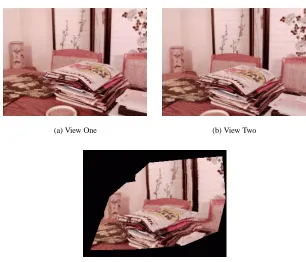
We implemented and tested a second application in the area of image-based rendering (IBR) in order to explore a more traditional form of data parallelism in the STM con-text. View transfer is the essential idea behind the IBR application: Given two images that have been placed in pixel-wise correspondence and a desired virtual camera view-point into the scene, a new image that depicts the scene from the desired viewview-point can be synthesized directly from the input pair [2, 17]. This approach to rendering is inter-esting because its complexity is a function of image size rather than scene complexity. See Figure 10 for an example of a synthesized image.
There are two main steps in synthesizing a new view through IBR once the cor-respondences have been obtained off-line: computing the initial transfer and filling in holes through interpolation. We use an Elliptical Weighted Averaging (EWA) tech-nique for interpolation [10], in which adaptively-sized interpolant kernels are applied to image locations with missing texture. Both the view transfer and EWA steps are good candidates for parallelization.
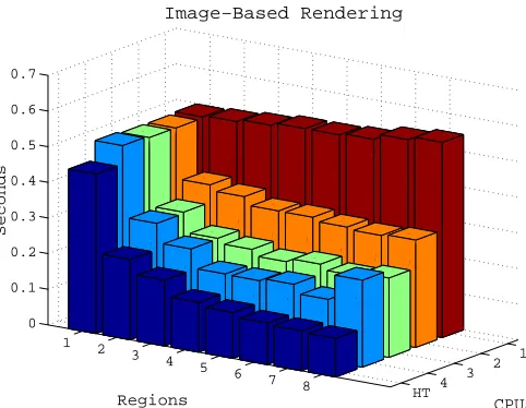
Data parallelism at the pixel-level is the main feature of the IBR application. Each image location can be processed independently of the others, with no sharing of data between neighbors. Our goal in this case was to demonstrate that the STM framework can also be profitably applied to this problem, which is closer to traditional fine-grained parallel vision applications. In this case we divided the image up into a parameterized number of regions, where each region could be processed in parallel. We created a separate thread for each region, and measured the average execution time as the number of regions varied from one to eight and the number of processors varied from one to four. The total set of measurements are plotted in Figure 11.
4.2 Image-Based Rendering 21
(a) View One (b) View Two
[image:25.612.124.430.122.384.2](c) Synthesized view
Figure 10: Input pair (a) and (b) and synthesized third view (c) in an image-based rendering application.
that did not use the STM infrastructure, but instead used lower-level synchronization operations (mutexes) and the hardware shared memory of the AlphaServer. This im-plementation used four processors and was tested on the same set of regions. These numbers are labeled “HT” (for hand-tuned) in the figure. The same data is displayed as superimposed 2-D plots in Figure 12.
There are several interesting observations we can make regarding the performance numbers for the STM experiments. In the case where there is only a single CPU, total execution time increases slightly with the number of regions. This reflects the addi-tional system-level overhead from context switching as the number of threads grows. Within each of the experiments plotted in Figure 12, the STM implementations show significant speed-ups as the number of image regions is increased until they exceed the number of CPU’s, at which point the speed-up tails off.
HT 4
3 2
1
1 2
3 4
5 6
7 8 0
0.1 0.2 0.3 0.4 0.5 0.6 0.7
CPUs
Image−Based Rendering
Regions
[image:26.612.211.452.125.312.2]Seconds
Figure 11: Bar graph of execution times from image-based rendering experiments. The rows labeled 1–4 correspond to the STM implementation with 1–4 processors. The row labeled HT shows the performance of a hand-tuned implementation on 4 processors.
there is no pipelining, the view transfer and EWA steps are sequential. In this case, semaphores can be used to suspend the EWA threads while the view transfer threads are active, and vice versa. This semaphore mechanism is more efficient than the thread yield mechanism which is used in the STM implementation. It ensures that the unused threads consume essentially no system resources.
The second optimization came from exploiting the nonuniformity of the computa-tional requirements in the EWA step. In EWA, the amount of work done in a region is a function of the number of “holes” in the image that must be filled in. Some re-gions may have no holes, some rere-gions may have many. When the number of threads is equal to the number of regions, some threads do little work but still contribute to the overhead. In the HT implementation there were only four threads, one per CPU, and the regions were scheduled on these threads by the application using a round-robin policy. This explains the additional speed-up in the case where the number of regions increased from four to eight.
There are two lessons from this experiment. The first is the obvious point that code which is hand-tailored to an application will almost always outperform code which uses a more general infrastructure. However, in addition to raw performance we must also consider the ease of development for each implementation. The development of both versions took on the order of hours. However, the STM version was developed by vision researchers who were not experts in programming SMP’s. In contrast, the HT application was developed by an expert with a great deal of experience in porting applications to this platform.
23
1 2 3 4 5 6 7 8
0.1 0.15 0.2 0.25 0.3 0.35 0.4 0.45 0.5 0.55 0.6
Regions
Seconds
Image−Based Rendering
[image:27.612.174.385.125.298.2]HT 4 3 2 1
Figure 12: Plots of execution times from image-based rendering experiments. This is the same data as the IBR bar graph.
begun an investigation into more principled schemes for integrating data parallelism into the STM framework. Some preliminary results are described in [20]. We plan to repeat the IBR experiments using our new framework in future work.
Another metric for comparing these implementations is portability. Repeating the STM experiment on a cluster setting would be trivial, as we recently completed an implementation of the STM on a cluster of SMP’s in our lab (see [19]). We plan to conduct this experiment in future work. In contrast, the prospects for porting the HT implementation to a cluster are not nearly as promising. Shared memory support in a cluster setting is not widely available, and so a cluster implementation would require significant modifications to the code.
5
Previous Work
During the 1980’s and early 1990’s there was an explosion of effort in applying parallel computing to computer vision tasks (see the conference series [27]). On the hardware side, the vision community participated in the development of a broad variety of par-allel architectures. Representative commercial systems include SIMD machines such as CM-2 [12] and MasPar [15] and systolic/data-flow machines such as the Warp [1]. Experimental parallel computers included pyramid architectures such as the IUA [28] and reconfigurable machines such as PASM [22].
period of research produced considerable insight into the computational requirements of vision problems and the feasibility of high performance parallel solutions. Perhaps the most important lesson was the critical role parallel computing plays in enabling the application of computer vision to real-world tasks [6].
Today, commercial MIMD computers seem to be the most cost effective path to wide-spread use of parallel computing. Surprisingly, there has been little investigation into systematic methods for building vision applications on this type of architecture. Of course, the more traditional approach of exploiting fine-grained pixel-level parallelism with specialized architectures is still being pursued. Some examples are [16] and many papers in [27]. While this type of problem is undeniably important, many real-world vision applications will contain a mixture of different types of parallelism, suggesting that an architecture with maximum flexibility could have wider applicability.
In developing STM one of our goals is to make the use of parallel computing by the general vision research community more widespread by developing a software in-frastructure that is convenient and easy to use, and which runs on commodity parallel machines and operating systems. A system such as STM will not be able to achieve the peak performance of custom hardware on certain applications, but it may well have a much broader impact.
Portability is another key benefit of a software-only parallel solution such as Space-Time Memory. Applications which use the STM can run on any multiprocessor ma-chine that supports the abstraction, regardless of its underlying memory and communi-cation architecture. The STM is implemented as a C library and does not rely on any special features of a multiprocessor architecture. This simplifies the task of porting it to a new MIMD architecture considerably. By focusing on the portability of our ab-straction, we are trying to maximize the chance that it can migrate to new generations of multiprocessor computers.
Within the scalable and parallel computing research community there is a great deal of work that is relevant to STM. The STM abstraction may be viewed as a
struc-tured shared memory, in comparison to the transparent shared memory that many SMP
architectures support. Atomicity for reads and writes in the STM is at the level of channel items. As a consequence, there is considerable opportunity for aggregating and coalescing put operations based on the expected rates of execution of threads com-municated to the abstraction. We therefore expect our abstraction to be valuable in devising an efficient implementation for a cluster of SMP’s in which there is no hard-ware support for shared memory. This seems like a promising approach to large scale parallelism.
25
structured shared memory that can use the lower-level temporal synchronization and consistency guarantees of Beehive.
The idea of space-time memory has also been used in optimistic distributed discrete-event simulation [14, 9]. The purpose and hence the design of space-time memory in those systems is very different from ours. In those systems, space-time memory is used to allow a computation to roll-back to an earlier state when events are received out of order. In this paper, we have proposed Space-Time Memory as the fundamental building block around which the entire application is constructed.
6
Future Work
There are two compelling avenues for future work. The first is an experimental in-vestigation of the STM on a cluster of SMP nodes. We recently completed a cluster implementation of the STM. There are two avenues of experimental work we would like to pursue. The first is a more precise characterization of the overhead of the STM. The second avenue is a further investigation of the performance of the color track-ing and image-based rendertrack-ing applications. In a cluster setttrack-ing questions about the physical location of threads on distinct nodes have an impact in performance. There is also the opportunity to exploit the structure the STM imposes on memory accesses to optimize communication in a cluster setting. A basic question we plan to answer is how overheads differ within and across nodes in the cluster. This will influence the additional speed-ups that are available in a cluster setting.
The second important direction is the integration of task and data parallelism in the STM context. Some preliminary work on this problem is described in [20]. There we present a framework for incorporating data parallelism into a task-oriented description of an application. An important observation about applications like the kiosk is that the optimal division into task and data parallel components must be dynamic. For example, the parallel strategy for the color tracker which delivers the best performance changes with the number of targets being tracked.
Our ultimate goal is a wide-spread distribution of the STM to members of the vision community, and others who may find it useful for their applications. In particular, we would like to quantify the impact of the STM in enabling developers who are not experts in parallel computing to exploit parallelism in their applications. One step towards this goal is to partner with a small number of university research groups who would be interested in adopting the STM as a development platform. A second step is to port the STM implementation to the NT operating system. The STM currently runs on a cluster of AlphaServers under DIGITAL UNIX. An NT port is currently in progress.
7
Conclusions
appli-cation class and described its computational properties, using the example of a Smart Kiosk user-interface.
The STM abstraction provides a high level programming model which simplifies the task of sharing time-varying data between threads in a parallel program. We have demonstrated the application of the STM to two vision problems: color-based tracking and image-based rendering. In both cases, the STM delivered significant speed-ups. We believe that the STM can be useful across a broad range of interactive applications, including computer graphics animation and multimedia indexing, retrieval, and editing.
Acknowledgments
The authors would like to thank Kath Knobe for many valuable discussions and for her extensive comments on this manuscript which improved it substantially. Kath, James Hicks, and Mark Tuttle also provided an excellent sounding board for ideas during the development of the STM.
References
[1] M. Annaratone, E. Arnould, T. Gross, H. T. Kung, M. Lam, O. Menzilcioglu, and J. A. Webb. The Warp computer: Architecture, implementation, and perfor-mance. IEEE Transactions on Computers, 36(12):1523–1538, December 1987.
[2] S. Avidan and A. Shashua. Novel view synthesis in tensor space. In Conference
on Computer Vision and Pattern Recognition, pages 1034–1040, San Juan, Puerto
Rico, June 1997.
[3] M. Ben-Ari. Principles of Concurrent Programming. Prentice-Hall, 1982.
[4] A. D. Christian and B. L. Avery. Digital smart kiosk project. In ACM SIGCHI
’98, pages 155–162, Los Angeles, CA, April 18–23 1998.
[5] R. Cipolla and A. Pentland, editors. Computer Vision for Human-Machine
Inter-action. Cambridge University Press, 1998. In press.
[6] J. D. Crisman and J. A. Webb. The Warp machine on Navlab. IEEE Transactions
on Pattern Analysis and Machine Intelligence, 13(5):451–465, May 1991.
[7] T. Darrell, G. Gordon, J. Woodfill, and M. Harville. A virtual mirror interface using real-time robust face tracking. In Proceeding of the Third International
Conference on Automatic Face and Gesture Recognition, pages 616–621, Nara,
Japan, April 14–16 1998.
[8] Proc. of Third Intl. Conf. on Automatic Face and Gesture Recognition, Nara, Japan, April 14–16 1998. IEEE Computer Society.
REFERENCES 27
[10] N. Greene and P. Heckbert. Creating raster Omnimax images from multiple perspective views using the Elliptical Weighted Average filter. IEEE Computer
Graphics and Applications, pages 21–27, June 1986.
[11] S. P. Harbison and G. L. Steele, Jr. C: A Reference Manual. Prentice-Hall, 2nd edition, 1987.
[12] D. Hillis. The Connection Machine. MIT Press, 1985.
[13] IEEE. Threads standard POSIX 1003.1c-1995, 1996. (also ISO/IEC 9945-1:1996).
[14] D. R. Jefferson. Virtual time. ACM Transactions on Programming Languages
and Systems, 7(3):404–425, July 1985.
[15] T. M. Jochem and S. Baluja. A massively parallel road follower. In Proc. of
Comp. Arch. for Machine Perception (CAMP ‘93), New Orleans, LA, December
1993.
[16] T. Kanade, A. Yoshida, K. Oda, H. Kano, and M. Tanaka. A stereo machine for video-rate dense depth mapping and its new applications. In Computer Vision
and Pattern Recognition, pages 196–202, San Francisco, CA, June 1996.
[17] S. B. Kang. A survey of image-based rendering techniques. Technical Report CRL 97/4, Cambridge Research Lab., Digital Equipment Corp., August 1997.
[18] P. Maes, T. Darrell, B. Blumberg, and A. Pentland. The ALIVE system: Wireless, full-body interaction with autonomous agents. ACM Multimedia Systems, Spring 1996.
[19] R. S. Nikhil, U. Ramachandran, J. M. Rehg, K. Knobe, R. H. Halstead Jr., C. F. Joerg, and L. Kontothanassis. Stampede: A programming system for emerging scalable interactive multimedia applications. Technical Report CRL 98/1, Digital Equipment Corp. Cambridge Research Lab, Cambridge MA, May 20 1998.
[20] J. M. Rehg, K. Knobe, U. Ramachandran, and R. S. Nikhil. A framework for integrated task and data parallelism in dynamic applications. Technical Report CRL 98/2, Digital Equipment Corp. Cambridge Research Lab, Cambridge, MA, May 1998. To appear in4th Workshop on Languages, Compilers, and Run-Time Systems for Scalable Computers. Springer-Verlag. In press.
[21] J. M. Rehg, M. Loughlin, and K. Waters. Vision for a smart kiosk. In Computer
Vision and Pattern Recognition, pages 690–696, San Juan, Puerto Rico, June 17–
19 1997.