High Imperceptible Data Hiding using Remainder Method
Biswajita Datta
Assistant Professor, CSESt. Thomas College of Engineering & Technology,
Kolkata, India
Samir K. Bandyopadhyay
Professor, CSE CSE Department, University of Calcutta,Kolkata, India
Anurag Kedia
CSESt. Thomas College of Engineering & Technology,
Kolkata, India
ABSTRACT
In this paper we will propose a high quality image steganography technique which can hide secret data within an image in such a way so that it is imperceptible to human eye. This method solves the overlapping problem of remainder and use modulo operator efficiently for hiding purpose. First, we calculate the base eight equivalent of target string. That increases the hiding capacity as well as robustness of the stego image. Then the secret data can be hidden by remainder method. In our proposed work we alter the remainder of pixels in such a way so as to greatly reduce the image distortion caused by the hiding of the secret data. Experimental result checks the quality of stego image as well as compared with standard LSB technique and 3 LSB multi-bit image steganography technique. Experimental results have also demonstrated that the proposed scheme is secure against StirMark Benchmark 4.0.
General Terms
Security, Internet, Cryptography, Communication, Number System
Keywords
Steganography, Embedding, Extraction, Remainder method, Pre-processing, Post-Processing
1.
INTRODUCTION
Today Security becomes an important issue with the rise of Internet. Cryptography plays an important role in this area for a decade. It focuses on keeping the contents of a message secret whereas now the modern scientists are focuses on keeping the existence of a message secret [1]. Steganography is the security technique for invisible communication. Steganography defines as “covered writing” [2]. Both Steganography and cryptography are not alone perfect. Once the presence of hidden information is suspected, the purpose of steganography is partly defeated. Thus the strength of steganography can be amplified by combining it with cryptography [3].
Although the concept of steganography is used for a long decade but do not have any name. Hidden on the back of wax writing tables, written on the stomachs of rabbits or Tattooed on the scalp of slaves, invisible writing by the help of invisible ink at the time of World War II are the early use of Steganography [4]. In the digital world of today, namely 1992 to present, Steganography is being used all over the world on computer systems. Steganography should meet three challenges: Imperceptibility –unnoticeable to human eye. Robustness – survival capability when the host medium has been manipulated. Capacity –embed large amount of data without much distortion [5].
The information can be embedded within different cover media like text, audio, image video etc. Image Steganography is one mostly used steganography technique. Here image is considered as a cover media and target information is embedded within that cover media to form a stego image [6]. Image steganography techniques are worked in both spatial and transform domain. There are currently three popular methods applied in Image Steganography: LSB Substitution, Blocking, and Palette Modification [7]. Now-a-days image steganography become popular with region selection for hiding based on the limited power of the human visual system (HVS) [8].
2.
LITERATURE SURVEY
For a very long decade there are many steganography technique works for securing the Internet. Among different available techniques Least Significant Bit (LSB) insertion is a common and simple approach to embed information in an image file (Katzenbeisser, 2000) [9]. In this method the LSB of a byte is replaced with a bit of the secret message [10]. An optimal LSB substitution technique based on genetic algorithm is proposed by Wang et al. to improve the
stego-image quality [11]. Selected least significant bit
steganography change one of the pixel color components in the image according to the message’s bits to hide. The rest of bits in the pixel color component are also changed in order to get the nearest color to the original one in the scale of colors [12].
these consecutive pixels [19]. To give higher payload Wang has proposed also two new schemes based on modulo
operator. A novel mechanism using modulus operations for
embedding secret data into a cover image is proposed by Wang, S.J. They use modulus operation for selecting threshold that indicates how many bits of the secret image are being incorporated into the cover image [20].
3.
PROPOSED METHOD
The remainder method has a disadvantage of overlapping. In this method the remainder is obtained for different values of data when divided by the same number. For example 13/8 & 21/8 have same remainder of 5. So this remainder method cannot be used for hiding data in steganography due to large distortion. Also the remainder of a number cannot map to its exact dividend at the receiver side. That’s why some of the target data is lost when try to extract it from stego media. We try to solve this problem in our proposed work.
For solving the overlapping problem of remainder here the encoding process is divided in different steps. First convert target data to the base of octal then hide these octal digits as information under cover image. In this paper text is considered as target data and 8 bit gray scale image as cover media. Both encoding and decoding techniques are discussed below.
3.1
Data embedding
The whole procedure for encoding is divided into three parts: Preprocessing of target data, embedding of target data into the cover media and the technique for storing the target string length.
3.1.1
Preprocessing
The length of text should be multiple of 3 for preprocessing of target data. If it is not the multiple of 3 then least used special character is concatenated at the end of the target string to make its length as multiple of three.
For preprocessing every three character is cut from the input string, and then converted their ASCII into 7 bit binary. Then concatenate them to form 21 bit string and cut every 3 bits from this string to convert them to their octal equivalent. Let the string be “Image”. The length of this string is 5 which is not multiple of three, add “`” at the end of the string to make its length 6 which is now multiple of three. Now the following steps are performed for explaining the above process.
First the string is divided with 3 character each ‘Ima’, ‘ge`’. Take 1st three characters i.e. ‘Ima”.
ASCII of ‘I’, ‘m’, ‘a’ are 73, 109, and 97 respectively. Now these are converted in 7 bit binary i.e. ‘1001001’, ‘1101101’ and ‘1100001’
Then they are concatenated to form 21 bit string i.e. ‘100100111011011100001’
Now this string is divided by three bit each and converted them into decimal to get 7 octal digits i.e.
100 100 111 011 011 100 001 4 4 7 3 3 4 1
The same above procedure also applicable for the next three characters i.e. ‘ge`’ and ‘6 3 7 1 2 4 7’ be the resultant seven digit octal string.
After the above transformation “4 4 7 3 3 4 1 6 3 7 1 2 4 7” become target data. Now these octal digits are embedded into the cover image starting from the second row using remainder method. The embedding technique is discussed below.
3.1.2
Embedding using remainder method
During embedding the intensity of cover image pixels are divided by 8, and their remainders are taken. Then these remainders are compared with each octal digit. If they equal then the pixel value is unaltered otherwise pixel value is adjusted in such a way so that its remainder is equal to the octal digits.
Now let the segment of cover image matrix be A= [… 23 44 66 55 77 …
56 77 12 33 23 66 77 22 …]
and “4 4 7 3 3 4 1 6 3 7 1 2 4 7” string has to be embedded as target string into this cover image matrix. For explanation 1st value from the cover image segment is considered, then perform its modulus i.e. mod (23, 8) =7. The 1st digit from the target octal string is 4 which is not equal to 7. So it needs to adjust the pixel value to make its remainder equal to 4.
There are large numbers within 0 to 255 whose remainder is 4 (which are 28, 4, 12, 20 and many more). But if we replace 23 by any one of these values, creates huge distortion and we are fails to meet the challenges of steganography. So we consider only the two nearer values of 23 which we get by incrementing or decrementing certain amount from 23 and these are 28 in forward direction and 20 in backward direction. Among these two 20 is more nearer than 28 because 23-20=3 whereas 28-23=5. So 23 is replaced with 20 instead of 28. Some mathematical rules are discussed below by which the selection is done.
First the cover pixel (p) is divided by 8 and the remainder is found out. Then the remainder value is compared with target octal digit and the forward and backward differences from these two values are calculated by the following equation: if the remainder (r) of cover pixel (p) is less than or equal to the target octal digit (d) i.e. r <= d then Forward Difference f:= d - r
and Backward Difference b:= r + 8 - d. Otherwise i.e. if r > d then
Forward Difference f: = d + 8 - r and Backward Difference b := r - d
For example if we consider 23 as cover pixel value (p) and 4 as target octal digit then r:= 23 / 8:=7and d:= 4
i.e. r > d so Forward Difference f:= d + 8 - r = 4 + 8 – 7 =5 and Backward Differences b:= r – d:= 7 – 4:= 3.
Now by comparing forward and backward differences the nearest value of cover pixel whose remainder is equal to the target octal digit is decided. That is done by the following steps:
if Forward Difference (f) is less than Backward Difference (b) then the cover pixel value is incremented f decimal places so that its remainder becomes d and the modified value then becomes the corresponding stego pixel value (sp) i.e.
so that its remainder becomes d and the modified value then becomes the corresponding stego pixel value (sp) i.e.. if f > b then sp:= p – b and flag:= 0 (flag used for f=b case) if Forward Difference (f) is equal to Backward Difference (b) then either the cover pixel value is incremented f decimal places or decremented b decimal places based on the change of previous cover pixel value. The modified value then becomes the corresponding stego pixel value (sp) i.e. if f = b then sp:= p + f when flag = 1
Otherwise sp:= p - b when flag = 0.
The Forward (f) and Backward (b) Differences of previous example are 5 and 3. The cover pixel (p) value is 23.
Since f > b then stego pixel value sp is 20 (sp:= p –b:= 23 – 3:= 20) and flag:= 0.
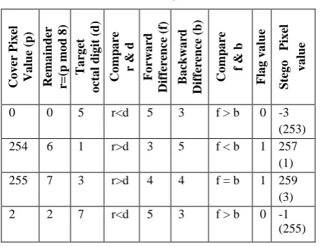
Boundary value of the pixels creates some problem in our proposed method. The problems are shown in the following table.
Table 1: Problem with Boundary Value of the Pixel
Co v er Pi x el Va lu e (p ) Re m a in d er r= (p m o d 8 ) Ta rg et o cta l d ig it (d ) Co m p a re r & d Fo rwa rd Diffe re n ce (f) Ba ck wa rd Diffe re n ce (b ) Co m p a re f & b Fl a g v a lu e S te g o Pi x el v a lu e
0 0 5 r<d 5 3 f > b 0 -3
(253)
254 6 1 r>d 3 5 f < b 1 257
(1)
255 7 3 r>d 4 4 f = b 1 259
(3)
2 2 7 r<d 5 3 f > b 0 -1
[image:3.595.53.284.306.483.2](255) From Table 1 it is seen that if the actual replacement rule on cover image is followed then the boundary value gives the high distortion in the stego image. Here this problem is also solved by considering some rule. That is if the modified pixel value is less than 0 or greater than 255 by either considering forward or backward differences, then the cover pixel value is replaced by the other difference i.e. backward and forward differences. That is explained by showing the result of the Table 1 in the Table 2.
Table 2: Solution for Boundary Value Problem
3.1.3
Storing the Length of Target Text
Now for extraction it is need to store string length within the cover image. The string length is stored as string instead of number. The technique is divided into two parts: first storing the length of string length, then the storing of actual string length as a string.
The Length of string length is calculated from number of digits present within string length. Then this value stored at the first row of cover pixel using standard LSB Technique. Let “Image” is target data then the length of it is 5. Number of digit within 5 is 1 so the length of the target string length is 1. This value is now converted in 8 bit decimal i.e. 00000001. These 8 bits are now embedded at the first row of cover media using LSB technique.
The string length is stored at the last row of cover image using the proposed remainder technique. For this the length of string should be multiples of three. If not then it is necessary to make it multiple of three. From the above example the string length is “5”. Now this “5” is considered as a string instead of number for storing and pass through preprocessing stage. Then remainder method is used to store it.
3.2
Data extraction
The decoding method at the receiver side also divided into three major steps: extraction of data using Remainder method, Post-processing of data and before this two steps length extraction.
3.2.1
Target string length extraction
First the length of string length is extracted from 1st row of stego image. Then the actual string length is extracted from the last row of the stego media using the remainder method for extraction and post processing which are discussed below.
3.2.2
Remainder method for Extraction
At the receiver side the affected (where the data is hidden) pixel values are divided by 8 and the remainders of this division are hidden octal string of Preprocess step of sender side. Now this is send to the post-processing technique to get the original target text.
Suppose [… 20 44 167 59 74 1 118 243 151 73 186 12 …] these are the affected pixel value of stego image on which the remainder method for extraction is applied. These modified pixel values of cover image are now divided by 8 and remainders are [4 4 7 3 2 1 6 3 7 1 2 4]. This is the octal string that is generated from the original target data by preprocessing technique used at the time of sender side encoding. Now this string is send to post-processing technique to get the original target text at the receiver side.
3.2.3
Post-processing
The resultant octal string is the input to this stage. Here each octal digit is converted to their 3 bit binary equivalent. Each of these 3 bits is concatenated to form a binary string. Then every 7 bits are cut and converted to their corresponding decimal equivalent. Then the characters of these ASCII values are concatenated up to the extracted string length to get the original target string.
Let the input octal string is [4 4 7 3 3 4 1 6 3 7 1 2 4 7]
The 3 bit binary equivalent of these digits are [100 100 111 011 011 100 001 110 011 111 001 010 100 111]
Co v er Pi x el Va lu e (p ) Ta rg et o cta l d ig it (d ) Fo rwa rd Diffe re n ce (f) Ba ck wa rd Diffe re n ce (b ) S te g o Pi x el v a lu e (b y a ctu a l ru le) S te g o Pi x el v a lu e (fo r re d u cin g t h e d isto rtio n )
0 5 5 3 -3(i.e. 253) 0+5=5
254 1 3 5 257 (i.e. 1) 254-5=249
255 3 4 4 259 (i.e. 3) 255-4=251
After concatenating
[100100111011011100001110011111001010100111] this binary string is formed.
Now this are grouped into 7 bit each – [1001001 1101101 1100001 1100111 1100101 0100111]
Their Corresponding ASCII are [73 109 97 103 101 39] According to string length of target text it is 5 so the first 5 ASCII values are consider for Target string [73 109 97 103 101].
Now the Target string is “Image”.
4.
ALGORITHM FOR PROPOSED
METHOD
4.1
Algorithm for embedding target text
within a cover image
Step 1: Start
Step 2: Read the target text file and Cover image. Step 3: Store the length of the target text. Step 4: Preprocess the Target text.
Step5: Embed preprocessed target text from the second row of the cover image matrix using remainder method. Step 6: Send the obtained Stego Image to the receiver. Step 7: End
4.1.1
Storing the Length of the Target Text
Step 1: Hide the length of target string length using LSB technique.Step 2: Preprocess the string length.
Step 3: Then hide preprocessed string length from the last element of the last row of the cover image matrix using remainder method.
Step 4: Return
4.1.2
Preprocessing
Step 1: Make the length of input string as a multiple of 3. Step 2: Convert ASCII of each Character into 7 bit binary. Step 3: Group the array elements into 3 bits each and convert them to their corresponding Octal equivalents. Step 4: Return
4.1.3
Proposed Remainder Method
Step 1: Read a pixel value of the cover image matrix and find modulus 8 of this pixel.
Step 2: Consider a digit of target octal string. Step 3: Calculate Forward and Backward Differences. Step 4: Compare them and decide the adjusted value. Step 5: Modify the cover pixel value with this adjusted value. Step 6: repeat above steps for the length of the octal string. Step 7: Return
4.2
Algorithm for extracting target text
from a Stego image
Step 1: Read the stego image matrix. Step 2: Extract the string length.
Step 3: Extract the target octal string using modulo operator. Step 4: Post-process the extracted octal string to get the original target string.
Step 5: End
4.2.1
Eextraction of string length
Step 1: Extract the length of the string length, from the LSB of first 8 pixels of Stego Image.
Step 2: Extract string length using remainder method for
Step 3: Post-process the extracted string length to get the actual string length.
Step 4: Return.
4.2.2
Extracting target data using proposed
Remainder method
Step 1: Calculate Octal String length.
Step 2: Read a pixel value of the stego image matrix and find modulo 8 of this pixel.
Step 3: This remainder is the embedded octal digit.
Step 4: Repeat step 2 and 3 for the length of the octal string. Step 5: Concatenate remainders to get the target octal string. Step 6: Return.
4.2.3
Post-processing
Step 1: Convert each digit of Octal string into 3 bit binary and concatenate to get a binary String..
Step 2: Group the bits of this string, 7 at a time, and convert each of these groups into their corresponding decimal value to get the ASCII equivalents.
Step 3: Repeat the above steps for the string length. Step 4: Convert the ASCII value to get the original target string.
Step 5: Return.
5.
RESULT & ANALYSIS
In this section first we show the experimental results of the proposed technique in Fig. 1. Then the analysis of the proposed technique is done with existing relevant methods based on quality and capacity analysis of cover media. Also a standard benchmark tool – StirMark Benchmark is used for performance analysis of proposed technique.
Target text is chosen for embedding into the cover image are of three types based on their size. Text file with no. of characters less than 100 is considered to be small. Text file with no. of characters in the range of 100-500 is considered to be medium. Text file with no. of characters greater than 500 is considered to be large. As a cover image we consider uncompressed gray scale image file of different size. The images are including landscapes, people, jungles, animals, motion, single object image and many more.
5.1
Analysis based on image quality
The image quality of the output stego images are analyzed by histogram analysis, MSE and PSNR calculation, Euclidian distance measurement.
5.1.1
Histogram analysis
An image histogram acts as a graphical representation of the tonal distribution in a digital image. It plots the number of pixels for each tonal value. From Fig. 1 we observe that there are no significant changes in frequency of appearance of the gray shades by comparing the histogram of cover image with the stego image.
5.1.2
PSNR and MSE calculation
The PSNR (Peak Signal to Noise Ratio) is used to measure the quality of stego image compared to the cover image and is calculated by equation (1), where MSE defined in equation (2) refers to Mean Square Error.
db MSE
PSNR
255
2
log
10 .……..……….... (1)
m nC
i
j
S
i
j
mn
Where m, n are the width and height of Cover (C) and Stego (S) image matrix.
(a) Tulip (b) Tulip Stego
(c) (d)
(e) Lenna (f) Lenna Stego
(g) (h)
(i) Motion (j) Motion Stego
(k) (l)
(m) Crowdy (n) Crowdy Stego
(o) (p)
(q) Scenery ( r) Scenery Stego
(s) (t)
(u) Jungle (v) Jungle Stego
(w) (x)
Fig.1: Experimental Result. (b), (f), (j), (n), (r) and (v) are the stego images of (a), (e), (i), (m), (q) and (u). (c), (g), (k), (o), (s) and (w) are histogram of the cover images. (d), (h),
(l), (p), (t) and (x) are the histogram of corresponding stego images.
Fig 2: MSE for Same Target Text Embedded in Different Cover Image
[image:6.595.52.281.234.393.2]Fig 3: PSNR for Same Target Text Embedded in Different Cover Image
Fig 4: MSE Different Size Target Text Embedded in Same Cover Gray Scale Image
Fig 5: PSNR Different Size Target Text Embedded in
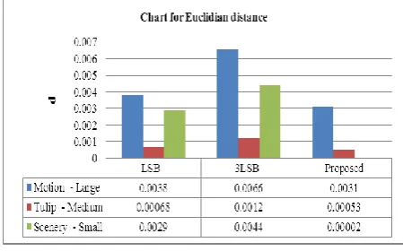
5.1.3
Calculation of Euclidian distance of image
The Euclidean distance (d) of the cover and stego images is used to show that there is not much change in the intensity perception of the two images. The objective of this measure is to perceptibility of proposed technique. If the Euclidean distance is very high then there is a possibility that pixels have been changed more with its intensity.
c
c
d
1
2
2……….……...………. (3)Where c1 and c2 are the pixel values of the cover and the stego image respectively.
Fig 6: Euclidian distance Measurement
5.1.4
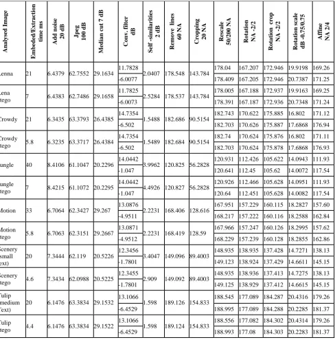
Analysis based on StirMark benchmark 4.0
StirMark Benchmark Version 4.0 was introduced on January, 2012 for the fair evaluation procedures for steganography. Different tools like Embedded/Extraction time, Add noise, Median Cut, Self-similarities, Convolution filter, cropping, rotation, PSNR and many more are used for better analysis of stego image with its cover image. Now we analyze the efficiency of our proposed technique based on this standard benchmark tool and the corresponding results are shown in Table 3.5.1.5
Embedding Capacity of Cover image
We analyze capacity of cover media based on the number of target bits embedded within that media. Capacity is again inversely proportional to robustness as well as perceptibility. So our aim is to increase capacity without any noticeable distortion. We also compare our proposed technique with both LSB and 3LSB technique to so efficiency of it.From Table 4 it is observed that provide more capacity than standard LSB technique. In case of standard LSB minimum c * 7 number of pixels are required to store c different characters whereas for 3LSB multi-bit and our Proposed Remainder Technique it is c*7/3. Since in Multi bit 3LSB technique 3 different target bits are embedded into a single pixel and in Proposed Technique 3 different bits of target text are used for creating octal digit. Similarly in the case of our proposed technique and that is embedded into a cover pixel. That’s why Embedding Capacity of a Cover image using 3LSB and our proposed method is 3 times more than that of using Standard LSB technique.
Our proposed technique is better than 3LSB multi-bit steganography in respect to perceptibility but not than standard LSB technique. In the case of LSB single bit embedded at the LSB of cover pixel and the maximum error
cause for this embedding is 21-1 i.e. 1 intensity value. In the
[image:6.595.53.281.427.568.2] [image:6.595.53.283.597.743.2]Table 3: StirMark Benchmark Results Ana ly se d I m a g e Em b ed ed /Ex tr a ctio n tim e m s Add n o ise 2 0 d B J p eg 1 0 0 d B Medi a n c u t 7 d B Co n v . fil te r dB S el f -sim il a riti es 2 d B Re m o v e l in es 6 0 NA Cr o p p in g 2 0 NA Re sc a le 5 0 /2 0 0 NA Ro ta ti o n NA -2 /2 Ro ta ti o n cr o p NA -2 /2 Ro ta ti o n sc a le d B -0 .7 5 /0 .7 5 Affin e NA 2 /4
Lenna 21 6.4379 62.7552 29.1634
11.7828
2.0407 178.548 143.784
178.04 167.207 172.946 19.9198 169.26
-6.0077 178.409 167.205 172.946 20.7387 171.25
Lena
stego 7 6.4383 62.7486 29.1658
11.7825
2.5284 178.537 143.784 178.005 167.188 172.937 19.9163 169.25
-6.0073 178.391 167.187 172.936 20.7348 171.24
Crowdy 21 6.3435 63.3793 26.4385 14.7354 1.5488 182.686 90.5154 182.743 170.622 175.885 16.802 171.12
-6.502 182.703 170.626 175.887 17.6868 176.94
Crowdy
stego 5.8 6.3235 63.3717 26.4384
14.7354
1.5489 182.684 90.5154 182.74 170.624 175.876 16.802 171.11
-6.502 182.703 170.624 175.878 17.6868 176.93
Jungle 40 8.4106 61.1047 20.2296 14.0442 3.9962 120.825 56.2828 120.931 112.426 105.622 14.0943 111.93
-1.047 120.641 112.45 105.62 14.0072 117.54
Jungle
stego 7 8.4215 61.1072 20.2295
14.0442
4.4926 120.827 56.2828 120.926 112.466 105.628 14.0951 111.93
-1.047 120.64 112.451 105.628 14.0082 117.54
Motion 33 6.7064 62.3427 29.267 13.0876 2.2231 168.406 128.616 167.951 157.229 160.115 18.2827 157.60
-4.9511 168.217 157.222 160.116 18.2588 162.84
Motion
stego 5.8 6.7063 62.3151 29.2667
13.0871
2.2231 168.419 128.59 167.966 157.247 160.126 18.2995 157.62
-4.9512 168.229 157.239 160.128 18.2855 162.86
Scenery (small text)
20 7.3444 62.119 20.5226 12.3456 3.4047 149.096 89.4003 148.935 138.935 137.428 14.7271 138.13
-1.7801 149.123 138.924 137.429 14.6611 145.15
Scenery
stego 4.6 7.3434 62.0988 20.5225
12.3455
2.909 149.092 89.4003 148.935 138.936 137.413 14.7275 138.13
-1.7801 149.125 138.929 137.412 14.6615 145.15
Tulip (medium Text)
20 6.1476 63.3834 29.1532
13.1066
1.598 189.126 154.833
188.545 177.089 184.287 20.4316 179.26
-6.4529 188.995 177.089 184.288 20.2285 181.37
Tulip
stego 4.4 6.1476 63.3834 29.1522
13.1066
1.598 189.124 154.833 188.556 177.082 184.302 20.4314 179.26
-6.4529 188.993 177.08 184.303 20.2283 181.37
Table 4. Capacity of Different Gray Scale Images to Embed Different Target Text
Co v er im a g e n a m e Co v er fil e siz e Dim en sio n o f co v er im a g e P = m × n × h BPP Te x t fil e siz e No . O f ch a ra cte rs in te x t fil e (c ) No . O f b its in te x t fil e A=c×7 No . O f p ix els re q u ire d in LS B te ch n iq u e B= A No . O f p ix els re q u ire d in 3 LS B te ch n iq u e B= A/3 No . O f p ix els re q u ire d in Re m a in d er te ch n iq u e B= A/3
Motion 2.69 MB 1024*768*8 3.05KB (large) 3130 21910 21910 2435 2435
Tulip 3.80 MB 1024*1024*8 332 bytes(medium) 322 2254 2254 251 251
Scenery 7.36 MB 1920*1200*8 22 bytes (small) 22 154 154 18 18
bits are affected together by 3 bits of target data and the
maximum error cause for this embedding is 22 + 21 + 20i.e 7.
But in the case of our proposed technique the maximum
[image:7.595.51.550.610.722.2]backward differences is considered then the change of cover pixel value after adjustment is never greater than four. The fig 7 helps us to understand why the change of cover pixel is maximum 4.
Fig: 7 Perceptibility Measurements
Our Proposed Technique is robust in the sense that if anyone can able get embedded target data from stego media they do not get the original target text without knowing the post-processing technique; they just get the octal string.
6.
CONCLUSION
This paper proposes a high quality steganography technique using remainder method. Here the overlapping problem of remainder is solved by adjusting pixel values with minimum distortion. Also the preprocessing step for target data provides more robustness to this propose method. Experimental result also compared with the standard LSB technique and 3LSB multi-bit technique. It shows better performance than 3LSB multi-bit steganography in respect to imperceptibility. Although with respect to capacity the multi-bit technique as well as our proposed technique is same but is better than standard LSB technique. Experimental results also tested with respect to StirMark Benchmark version 4.0 and give satisfactory results.
7.
REFERENCES
[1] Diffie, W. and Hellman, M. E. 1977. “Exhaustive Cryptanalysis of the NBS Data Encryption Standard”. IEEE Computer, Vol. 10, pp. 74- 84.
[2] Provos, N., Honeyman, P. 2003. “Hide and seek: An introduction to steganography”. IEEE Security & Privacy Magazine 1, pp. 32-44.
[3] Anderson, R. J., Petitcolas, F. A. P., “On the limits of steganography”, IEEE Journal of selected Areas in Communications, May 1998.
[4] Jamil, T. 1999. “Steganography: The art of hiding information is plain sight”, IEEE Potentials, Vol. 18, No. 01.
[5] Silman, J. 2001. “Steganography and Steganalysis: An Overview”. SANS Institute.
[6] Johnson, N. F., Jajodia, S., “Exploring Steganography: Seeing the Unseen”, Computer Journal, Feb. 1998. [7] Zhang, X., Wang, S., Zhou, Z. 2008. “Multibit Assignment
Steganography in Palette Images”. IEEE Signal Processing Letters, Vol. 15.
[8] Luo, W., Huang, F., Huang, J. “Edge Adaptive Image Steganography Based on LSB Matching Revisited”. IEEE Transactions on Information Forensics And Security, Vol. 5, No. 2, Jun. 2010.
[9] Kurak, C., McHugh, J., “A Cautionary Note on Image Downgrading”. In Proc. of IEEE 8thAnnual Computer Security Applications Conference. San Antonio, USA, Nov./Dec. 1992, pp. 153-155.
[10] Chan, C. K., Cheng, L. M., “Hiding data in images by simple LSB substitution”, Pattern Recognition, pp. 469– 474, Mar. 2004.
[11] Wang, R. Z., Lin, C. F., Lin, J. C., “Image hiding by optimal LSB substitution and genetic algorithm”. Pattern Recognition 34, pp.671–683, Mar. 2001.
[12] Roque, J. J., Minguet, J. M. 2009. “SLSB: Improving the Steganographic Algorithm LSB”. Workshop on Security in Information Systems WOSIS.
[13] Kumari, L., Goyal, D., Gyan, S. “Analysis and Design of 3 LSB Techniques for Secure Audio Steganography”. International Journal of Advanced Research in Computer Engineering & Technology (IJARCET) Vol. 2, No. 8, Aug. 2013.
[14] Nguyen B. C., Yoon S. M., Lee H. K. 2006. “Multi Bit Plane Image Steganography”. IWDW, LNCS 4283, pp. 61–70.
[15] Tripathi A., Nair J. S. “Steganography Using Segmenting Mosaic Images with Embedding Data by 3 LSB S-Type Scanning”. International Journal of Latest Trends in Engineering and Technology (IJLTET) Vol. 2, No. 4 Jul. 2013.
[16] Zhang X., Wang S., Zhou Z. 2008. “Multibit Assignment Steganography In Palette Images”. IEEE Signal Processing Letters, Vol. 15.
[17] Kawaguchi E., Eason R. O. “Principle and applications of bpcs steganography”. In Proc. of SPIE 3528, Multimedia Systems and Applications Conference Vol. 3528, Nov. 01, 1998.
[18] Thien, C. C., Lin, J. C. “A simple and high-hiding capacity method for hiding digit-by-digit data in images based on modulus function”. Pattern Recognition 36, 2875–2881, Dec. 2003.
[19] Wang, C.M., Wu, N. I., Tsai, C. S., Hwang, M. S. 2008. “A high quality steganographic method with pixel-value differencing and modulus function”. The Journal of Systems and Software, pp. 150–158.