Technology (IJRASET)
Design and Verification of ACK / NAK Protocol of
PCI Express Data Link Layer in System Verilog
Gokulakrishnan S1, Radhakrishnan N2
Electronics and Communication Department, Easwari Engineering College
Abstract – PCI-Express is a high performance, general purpose I/O interconnect communication protocol for multiplexing various peripheral. PCI Express is third generation Computer Bus(3GIO) to inter connect peripherals in a Computer, Servers, Mobile sets and systems. It is the layered, packet approach serial bus protocol. And the transfer rate of GEN 4 PCI-Express is up to 16GTps, and the throughput is around 2GBps for X1 lane. It has three major layers -Transaction Layer, Data Link Layer and Physical Layer. The basic objective of this project is to designing and verifying the ACK/ NAK Protocol of PCI-Express Data Link Layer. The Primary responsibility of this layer is to assure the integrity of TLPs moving between devices, but it is also plays a part in TLP flow control, Link initialization and power management and convey information between the Transaction Layer above it and the Physical Layer below it. In performing this job, the Data Link Layer exchanges packets with its neighbor know as Data Link Layer Packets (DLLPs). DLLP are communicating between the Data Link Layers of each device. DLLPs of Data Link layer supports ACK / NAK Protocol. This work uses System Verilog to model different blocks of the ACK / NAK Protocol of Data Link Layer layer of PCI Express. The RTL code is designed and Verified using the ModelSim-Altera 6.3g_p1 (Quartus II 8.1) Web Edition.
Keywords – PCIE, TLP, DLLP, CRC, ECRC
I. INTRODUCTION
PCI-Express is a high performance, general purpose I/O interconnects defined for a wide variety of future computing and communication platforms. PCI- Express takes advantage of recent advances in point-to-point interconnects, switch based technology and packetized protocol to deliver new level of performance and features. Power management, Quality of Services (QoS), Hot-plug/ Hot-swap support, Data integrity and error handling are among some of the advanced features supported by PCI-Express.
The fundamental goal of this layering definition is to facilitate the reader’s understanding of the specification. Note that this layering does not imply a particular PCI-Express implementation. PCI-Express uses packets to communicate information between the components. Packets are formed in transaction and data link layers to carry the information from the transmitting component to the receiving component.
As the transmitted packets flow through the other layers, they are extended with additional information necessary to handle packets at those layers. At the receiving side, the reverse process occurs and packets get transformed from their physical layer representation to the data link Fig.1 Layering diagram of PCIE layer representation and finally (for TLP - Transaction Layer Packets) to the form that can be processed by the transaction layer of the receiving device.
Technology (IJRASET)
The data link layer is an intermediate stage between transaction layer and physical layer. Link acknowledgment time out replay mechanism, flow initialization protocol, error correction protocol and power management are some of the basic responsibilities of the data link layer. As shown in Fig.2, packet is assembled in transaction layer by appending header (3-4 DW) as start frame and ECRC (1 DW) as end frame. Again when the packet assembled in transaction layer passes through the data link layer, packet sequence (2 B) will be appended as start frame and LCRC (1 DW) will be appended as end frame. Again physical layer adds start frame and end frame of 1 Byte to data link layer packet. In this way, packet formations through the layer will be completed and finally it will pass through the link which is established between transmitter and receiver.
Fig.2 Packet formations through the layers
Data link layer also produce and consume the packets that are used for link acknowledgment and time out replay mechanism. As shown in Fig.3, To differentiate these packets from those used by transaction layer, the term Data Link Layer Packet (DLLP) will be used when referring to packets that are produced and consumed at the data link layer.
Fig.3 DLLP Packet format
II. PROPOSED ARCHITECTURE AND DESIGN
Technology (IJRASET)
Fig.4 Proposed architecture
A. Replay Buffer
The replay buffer stores the Data Link layer Packets (DLP). These DLPs include sequence number and Link CRC appended to the TLP. The TLPs are saved according to sequence number of arrival from the Transaction Layer before transmission. As successful reception of TLP at receiver side, ACK DLLP is sent back to the transmitter. It discards the associated DLPs from the Replay Buffer. If, on the other hand, the transmitter receives a NAK DLLP, it re-transmits the contents of the buffer.
B. NEXT_TRANSMIT_SEQ counter
This counter generates sequence number for incoming TLPs. The counter is a 12-bit counter that is initialized to 0 at reset, or when the Data Link Layer is in the inactive state. It increments until it reaches 4095 and then rolls over to 0 (i.e., it is a modulo 4096 counter).
C. LCRC Generator
The LCRC Generator provides a 32-bit LCRC for the TLP. The LCRC is calculated using all fields of the TLP including the Header, Data Payload, ECRC and Sequence Number. The receiver uses the TLP's LCRC field to check for a CRC error in the received TLP.
D. REPLAY_NUM Count
Technology (IJRASET)
E. REPLAY_TIMER Count
The REPLAY_TIMER is used to measure the time from when a TLP is transmitted until an associated ACK or NAK DLLP is received. The REPLAY_TIMER is started (or restarted, if already running) when the last Symbol of any TLP is sent. It restarts from 0 each time that there are outstanding TLPs in the Replay Buffer and an ACK DLLP is received that references a TLP still in the Replay Buffer. It resets to 0 and holds when there are no outstanding TLPs in the Replay Buffer, or until restart conditions are met for each NAK received (except during a replay), or when the REPLAY_TIMER expires. It is not advanced (i.e., its value remains fixed) during Link re-training.
F. ACKD_SEQ Count
This 12-bit register tracks or stores the Sequence Number of the most recently received ACK or NAK DLLP. It is initialized to all 1s at reset, or when the Data Link Layer is inactive. This register is updated with the AckNak_Seq_Num [11:0] field of a received ACK or NAK DLLP. The ACKD_SEQ count is compared with the NEXT_TRANSMIT_SEQ count. Also, the ACKD_SEQ count is used to check for forward progress made in transmitting TLPs. If no forward progress is made after 3 additional replay attempts, the Link is re-trained by physical layer.
G. NEXT_RCV_SEQ Count
The 12-bit NEXT_RCV_SEQ counter keeps track of the next expected TLP's Sequence Number. This counter is initialized to 0 at reset, or when the Data Link Layer is inactive. This counter is incremented once for each good TLP received that is forwarded to the Transaction Layer. The counter rolls over to 0 after reaching a value of 4095. The counter is not incremented for TLPs received with CRC error, nullified TLPs, or TLPs with an incorrect Sequence Number.
H. Sequence Number Check
After the CRC error check, this block verifies that a received TLP's Sequence Number matches the NEXT_RCV_SEQ count. If the TLP's Sequence Number = NEXT_RCV_SEQ count, the TLP is accepted, processed and forwarded to the Transaction Layer. NEXT_RCV_SEQ count is incremented. The receiver continues to process inbound TLPs and does not have to return an ACK DLLP until the ACKNAK_LATENCY_TIMER expires or exceeds its set value.
I. NAK_SCHEDULED Flag
The NAK_SCHEDULED flag is set when the receiver schedules a NAK DLLP to return to the remote transmitter. It is cleared when the receiver sees the first TLP associated with the replay of a previously - Nak'd TLP. The specification is unclear about whether the receiver should schedule additional NAK DLLP for bad TLPs received while the NAK_SCHEDULED flag is set.
J. ACKNAK_LATENCY_TIMER
The ACKNAK_LATENCY_TIMER monitors the elapsed time since the last ACK or NAK DLLP was scheduled to be returned to the remote transmitter. The receiver uses this timer to ensure that it processes TLPs promptly and returns an ACK or a NAK DLLP when the timer expires or exceeds its set value. The timer value is set based on a formula described in "Receivers ACKNAK_LATENCY_TIMER".
K. ACK/NAK DLLP Generator
This block generates the ACK or NAK DLLP upon command from the LCRC or Sequence Number check block. The ACK or NAK DLLP contains an AckNak_Seq_Num[11:0] field obtained from the NEXT_RCV_SEQ counter. ACK or NAK DLLPs contain a AckNak_Seq_Num[11:0] value equal to NEXT_RCV_SEQ count -1.
III. SIMULATION RESULTS
A. Simulation Output for Sequence Generator
Technology (IJRASET)
Figure 5. Waveform for Sequence Generator
B. Simulation Output for TLP stored in Replay Buffer
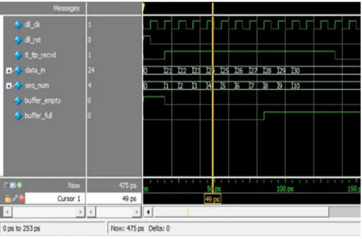
[image:6.612.185.444.313.459.2]The replay buffer stores the Data Link layer Packets (DLP). These DLPs include sequence number and Link CRC appended to the received TLP. The TLPs are saved according to sequence number of arrival from the Transaction Layer before transmission. When the transaction layer TLP packet received is enabled, then only the tlps are stored in retry buffer (refer figure 6). For each new arival of TLP it increase the sequence number one by one until the buffer is full.
Figure 6. Waveform for TLP stored in Replay Buffer
C. Simulation Output for Replay Buffer Full and Empty
[image:6.612.186.448.536.709.2]Technology (IJRASET)
D. Simulation Output for Reception of ACK DLLP
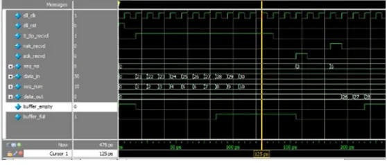
This block generates the ACK DLLP upon command from the LCRC or Sequence Number check block (refer figure 8). The ACK DLLP contains an AckNak_Seq_Num[11:0] field obtained from the NEXT_RCV_SEQ counter. ACK DLLPs contain a AckNak_Seq_Num[11:0] value equal to NEXT_RCV_SEQ count -1. When it receives ACK, it simply purges the TLPs from the Replay Buffer upto specified AckNak_Seq_Num.
Figure 8. Waveform for Reception of ACK DLLP
E. Simulation Output for Reception of NAK DLLP
This 12-bit register tracks or stores the Sequence Number of the most recently received NAK DLLP (refer figure 9). It is initialized to all 1s at reset, or when the Data Link Layer is inactive. This register is updated with the AckNak_Seq_Num [11:0] field of a received NAK DLLP. The ACKD_SEQ count is compared with the NEXT_TRANSMIT_SEQ count. If the error happened in receiver side due to LCRC and sequence number, then it is going to retransm it the TLPs that after the sequence number of NAK DLLP. And it purges the previous TLPs.
Figure 9. Waveform for Reception of NAK DLLP
F. Simulation Output for Reception of Repeated NAK DLLP
[image:7.612.192.471.386.505.2]After the TLPs retransmission there is a possibility to happen another NAK in the receiver side. It can retransmit up to next sequence of TLP to be entered based upon replay timer and replay counter. The REPLAY_TIMER is used to measure the time from when a TLP is transmitted until an associated ACK or NAK DLLP is received (refer figure 10).
Technology (IJRASET)
This 2-bit counter stores the number of replay attempts following either reception of a NAK DLLP, or a REPLAY_TIMER time-out. When the REPLAY_NUM count rolls over from 11b to 00b, the Data Link Layer triggers a Physical Layer Link-retrain
G. Simulation Output for Receiving TLP
[image:8.612.154.437.174.278.2]In this block explains about the receiver operation of the PCI Express endpoint. The incoming TLPs checked by LCRC processor, it generates the 32-bit LCRC value of the remaining 140-bits. And depends upon the correctness, it provide ACK as well as NAK signal (refer figure 11).
Figure 11. Waveform for Receiving TLP
H. Simulation Output for Transmitter and Receiver
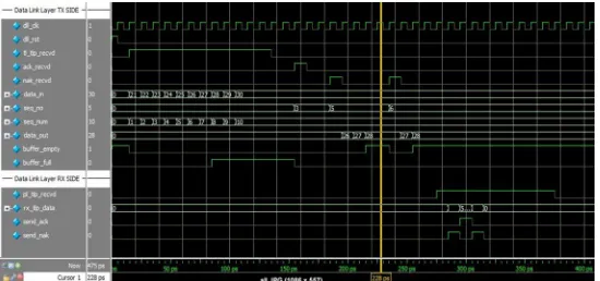
Complete simulation result that explains the full performance for transmitter and receiver operation. The TX and RX side operations of Data link layer are simulated (refer figure 12).
Figure 12. Waveform for Transmitter and Receiver
IV. CONCLUSION
From this paper, the ACK /NAK protocol of PCI-Express Data Link Layer Transmitter have been demonstrated. This presented design of PCIExpress Data Link Layer Transmitter and Receiver has the compatibility with all PCI-Express versions. By changing the parameters (constants) in the current design, it can be used in upcoming version i.e. PCIExpress to improve the data transfer rate.
V. FUTURE WORK
[image:8.612.162.437.350.479.2]Technology (IJRASET)
VI. ACKNOWLEDGEMENT
The results in this paper are from the work which was conducted as a Master Thesis by me in the field of VLSI Design, in cooperation with Easwari Engineering College, Chennai. I take the opportunity to heartily thank our project guide respected Mr. N. Radhakrishnan for his valuable guidance and touch of inspiration and motivation throughout the project. I am very grateful for those who supported and helped me during conducting this work.
REFERENCES
[1] “PCI Express Technology” by MindShare, Inc, Ravi Budrck and Mike Jakson, 2012.
[2] http://www.pcisig.com
[3] PCI-SIG, “PCI Express® Base Specification Revision 3.1a”, Retrieved 7th December, 2015
[4] Adam H. Wilen, Justin P. Schade and Ron Thomburg, Introduction to PCI Express: Intel press; 2003.
[5] M. Aguilar, A. Veloz, M. Guzman, “Proposal of Implementation of Data Link Layer of PCI-Express”, First International Conference on Electrical and
Electronics Engineering, 2004.
[6] PCI Express 1.1 Root Complex Lite x1, x4 IP Core User’s Guide, LATTICE SEMICONDUCTOR, February 2012.
[7] Peter Bohm, “Incremental and Verified Modeling of the PCI Express Protocol”, IEEE transaction on computer-aided design of integrated circuits and systems,
VOL. 29, NO. 10, October 2010.
[8] “PCI Express – An Overview of the PCI Express Standard”, August 13, 2009, retrieved from[online] www.ni.com/white-paper/3767/en/.
[9] Xilinx User Guide “LogiCORE IP ENDPOINT BLOCK PLUS v1.15 for PCI Express”, UG341 July 22, 2011.