Analysis of Complex Electromagnetic Structures by
Hybrid FDTD/WCIP Method
Gharbi Ramzi1, Zairi Hassen1, Trabelsi Hichem1, Baudrand Henri2
1Laboratory of Electronic, Department of Physics, Faculty of Science of Tunis, Tunis, Tunisia; 2Laplace Laboratory, Enseeiht, Rue Camichel, Toulouse Cedex, France.
Email: [email protected]
Received September 8th, 2012; revised October 14th, 2012; accepted October 24th, 2012
ABSTRACT
This paper proposes a hybrid full-wave analysis using Finite-Difference Time-Domain (FDTD) and Wave Concept Itera- tive Process (WCIP) methods, developed to analyze locally arbitrarily shaped microwave structures and Multilayer Planar structure. Using the equivalence principle, the original problem can be decomposed into two sub regions and solve each sub region separately. An interpolation scheme is proposed for communicating between the FDTD fields and WCIP wave, which will not require the effort of fitting the WCIP mesh to the FDTD cells in the interface region. This method is applied to calculate the scattering parameters of arbitrary (3-D) microwave structures. Applying FDTD to 3D discontinuity and WCIP to the remaining region preserves the advantages of both WCIP flexibility and FDTD effi- ciency. A comparison of the results with the FDTD staircasing data verifies the accuracy of the proposed method.
Keywords: FDTD; Hybrid Finite-Difference Time-Domain (FDTD); Hybrid Techniques; WCIP Method
1. Introduction
The WCIP method is a widely used numerical technique for characterizing various electromagnetic problems.
It has long been recognized that the accuracy and effi- ciency of the method can be dramatically improved through the use inhomogeneous layers and for planar structures with a curved boundary due to the staircasing approxi- mation.
Several researches have been developed to overcome these difficulties in the WCIP method. The effort spent by the researches to develop the WCIP method is re- stricted to study the homogeneous layers [1].
One attempt to study the inhomogeneous layers is pre- sented in [2,3]. This consists in hybridizing the WCIP method with a differential formulation using the differ- ential operator in conjunction with the Maxwell equation in their local form to link the waves on the two sides of the inhomogeneous layer [4].
Hybrid methods, which combine the desirable features of two or more different techniques, are developed to analyze complex electromagnetic problems that cannot be resolved conveniently, and/or accurately, by using them individually [5].
This paper proposes a new hybrid approach by intro- ducing an interpolation scheme for communication be- tween the FDTD field and the WCIP wave in the inter- face region. This approach employs a combination of
Fourier transformation and iteration process, and ex- changes information on the field values, back and forth, between the FDTD sub problem and the WCIP region. The iterative technique is rapidly convergent only when the mutual interaction between the two sub domains is relatively weak. The comparison between the scattering parameter results obtained with the proposed hybrid method, and FDTD stair casing data verifies the accuracy of this analysis.
2. Formulation
The idea of the hybrid approach consists to combines the above two methods in a manner that retains the advan- tages of both. Then, the hybrid method is implemented as follows:
First, the partition of the global domain in two sub domains:
Interior model or FDTD domain (3D discontinuity domain);
Exterior model or spectral domain (homogeneous domain).
Second, for the physical behavior, it is necessary to develop accurate procedures to support the Interaction between these two models, is fulfilled by enforcing boundary conditions, i.e., the continuity of the tangential fields on the equivalent surfaces S.
domain, into two sub domains DWCIP and DFDTD cor- responding to the WCIP and FDTD regions, respectively, such that D = DWCIP ∪ DFDTD.
Next, mesh these two regions using structured meshes, respectively, with common nodes shared at the interface but with no overlapping (DWCIP ∩ DFDTD = Ø).
The structured grid of the WCIP is well suited to con- forms the FDTD mesh at the interface, and this allows us to limit the number of unknowns in the FDTD region.
The FDTD and WCIP models describing the corre- sponding region are coupled together through the boun- dary conditions on the surfaces S:
1
1 2
ˆ ˆ
n n
Z Z
E E2
(1)
1
ˆ ˆ
nH n H2 (2)
Now, it is important to turn to the marching scheme that has been implemented in our algorithm. The FDTD technique a well-known and has been used widely, and hence, we do not need to quote his formulation in this work [6,7].
2.1. Formulation of the Wave Concept Iterative Method
The Wave Concept Iterative Process (WCIP) counts among the most recent and the most efficient iterative methods.
It was developed as an instrument for the study of guide wave and planar circuits, its applicability extends to all range of geometrical dimensions of the scattering obstacle. The WCIP approach consists in separating the structure under study into interfaces with upper and lower homogeneous media.
The boundary conditions on the interface are repre- sented by the diffraction operator, S, and in the homoge- neous media by Γ the reflection operator. They are de- fined in spatial and modal domains, respectively.
The two conditions for existence of the Wave Iterative formulation are: first, the partition of the global domain in two subdomains:
Spatial domain (interfaces or lumped elements);
Spectral domain (medium or propagation).
The Wave Concept method described here is based on full wave transverse formulation, where the dual quanti- ties current density and electric field are considered.
The incident A and reflected B waves are calculated
from the tangential electric E and magnetic H fields, on
the interface
0 0
0 0
1 2
1 2
i i
i
i i
i
Z Z
Z Z
A E
where indicates the medium 1 or 2 corresponding to a given interface Ω. Z0i is the characteristic impedance of the same medium (i) and Ji is the surface current den- sity vector given as
i i i
J H n (4)
where i is the outward vector normal to the interface. In general case the planar structures are modeled in the WCIP method by a thin metallic plate at the interface Ω
between two medium, enclosed by a rectangular wave- guide with transversal cut. The Γ operator is described in the modal domain and assigns the propagation boundary conditions at upper and lower interface.
n
The S operator expressed in the spatial domain assigns boundary conditions at the interface plan and represents the different possible sub domains (dielectric, metal and source). Then, the air-dielectric interface plan Ω is di- vided into cells (named pixels), forming a uniform grid, used to discretize each sub domain.
The spatial and modal waves are directly deduced from each other with the help of Fast Modal Transforma- tion (FMT) and its inverse transform (IFMT).
The decomposition of the electromagnetic wave in guided modes propagating in waveguide with electric or magnetic wall (TE and TM modes) takes place by the use of this Fast Modal Transformation.
The procedure is repeated until convergence of the in- put admittance Yin and the frequency parameter of the structure is obtained (The convergence is obtained once in Yin does not vary as the number of iterations increases) [8].
2.2. Hybrid WCIP-FDTD Algorithm
The hybrid method combines the method of WCIP in the frequency domain to solve the homogeneous problem and the FDTD method to handle the inhomogeneous di- electric object [9,10]. This approach employs a combina- tion of Fourier transformation and iteration, and ex- changes information on the field values, back and forth, between the homogeneous dielectric sub problem and the dielectric inhomogeneous region. The iterative technique is rapidly convergent only when the mutual interaction between the two sub regions relatively weak.
The hybridization technique is based upon the use of the concept of surface impedance boundary conditions it begins by dividing the original problem into two separate ones. The first one of these, which contains the inhomo- geneous or 3D discontinuity region, is solved by using the FDTD scheme, while the second, which deals with the homogeneous sub region, is handled via the WCIP scheme.
i i
i i
J
B E J
(3) A time-stepping solution procedure is implemented as follows.
Initial incident wave in the WCIP region can be ex- pressed as:
0 1 0
A (5)
The situation is equivalent to an ABC with free space impedance.
Initial excitation in the FDTD region can be expressed as:
0 1 0
B (6)
Begin the iteration process of the hybrid method by using the excitation source in the FDTD region and run- ning the conventional sub region. The FDTD region is surrounded by an impedance bounding surface (an equi- valence-principle surface) which is used to relaunch the inward and outward traveling fields between the two domains.
Next, the FDTD algorithm is applied in the relatively subregion, the equivalence principle is implemented in the 3D-FDTD computer code and all fields in this subre- gion is obtained.
Then updating the fields at the interface surface be- tween the two subregions, and will be used in the recon- structing the incident wave in the WCIP region.
0 0 1 2 i i i Z Z A E i iJ
(7)At the interface S of the FDTD domain the field rela- tion defined as flows:
0
Ζ
E J (8)
The surface current density vector given as: ˆ
n
J h (9)
ˆ
n is the outward vector normal to the interface. Ζ0 a
characteristic impedance. Then
1 0 , i t t a
x y Z A E (10)
,t x y
e = the electric fields on interface surface S of the
FDTD model.
Apply the FFT on the expression of the incident wave to pass the time domain to frequency domain, and can be used in the initial condition in the WCIP processes.
Starting the WCIP process, it has already been seen that B waves can be determined if A waves are known
and vice versa. The reflected wave B can be computed by applying the basically boundary conditions of the WCIP technique in the homogeneous media represented by the reflection operator.
ˆ
B A (11)
After convergence of the iterative process of the WCIP
approach. The reflected waves B is modeled by equiva- lent source of the internal impedance Z0 and are defined
as follows:
00
0 0
1
2 Z Z 2 Z
E
B E J (12)
02 Z0
E B (13)
The continuity boundary conditions at the equivalent surface according to the two sub regions are written as [12,13]:
Metallic domain
0 x y
E E (14)
0
0 Z
E
J (15)
Dielectric domain
0
0i si
Z Z
E
J (16)
0 0 si i s Z i Z Z E
E (17)
i i i
J H n
i
H et Ei magnetic and electric field.
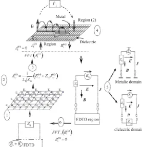
Z0i a characteristic impedance of the medium (i). Applying the IFFT of the electric fields at the interface S according to the WCIP scheme, the magnetic fields can then be evaluated from the electric field along the inter- face between WCIP region and FDTD region and are used as the excitation source for the sub region solved by the FDTD procedure. The procedure can now be repeated to continue the iteration process shown in Figure 1. The
solution is checked at each iteration step until a steady state solution is obtained and illustrated by Figure 2.
Accurate solution to the hybrid problem can be achi- eved by a minimal cost of iterations verified in Figure 3.
3. Numerical Results
Wave concept iterative process and Finite Difference-Time Domain (FDTD) techniques have been used to characte- rize essentially commonly found discontinuities.
Specifically, a microstrip short circuit, a Short-Cir- cuited Stubs microstrip Filter, and a rectangular dielectric resonant antenna were analyzed and their electrical per- formance was studied.
Figure 1. Schematic processes of the hybrid FDTD-WCIP approach.
Figure 2. Hybrid method algorithm.
region is replaced by the FDTD region, as shown in Fig- ure 1. Since the microstrip and ground plane coincide
with the top and the bottom boundaries of the FDTD region and, the Dirichlet boundary conditions are applied to the top and the bottom as well as the via-hole cylinder wall [11]. The hybrid technique reduces the computa- tional cost in the FDTD analysis and increases the com- putational efficiency.
The parameters of the first analyzed via-hole grounded microstrip structure presented in Figure 4 are as follows:
via-hole diameter is 0.6 mm, microstrip width is 2.3 mm, and substrate thickness is 0.794 mm. lastly, the substrate has a low dielectric constant (εr = 2.3).
The derived results from the present method agreed very well. It has been found that a via at the center of a microstrip line provide a good dc connection at higher frequencies resulting in substantial coupling between the
[image:4.595.57.287.526.698.2]r
0
h
z
y
[image:5.595.63.278.83.203.2]w
Figure 4. The via-hole grounded microstrip.
two sections of the line shown in Figure 5.
This hybrid method can be applied toward analyzing 3-D locally arbitrarily shaped structures accurately and efficiently. The next example is a three short-circuited stubs distributed highpass filter presented in Figure 6,
designed using the conventional technique [12-14]. For which the design parameters are: Cut-off frequency, fc = 1.3 GHz, the dielectric Constant is εr = 2.2 and the height of substrate is h = 1.57 mm, Characteristic impedance of terminating microstrip line, Z0 = 50 Ω, Guided wave- length λgc = 167.24 mm, corresponding width of the mi- crostrip = 4.83 mm, Number of stub elements, n = 3 [14].
The electrical characteristics of the ground connection vs. frequency as evaluated by FDTD and WCIP are shown in Figure 7 and demonstrate very good agreement
between the two methods. The slight discrepancy be- tween the values can be attributed to numerical errors as- sociated with both techniques.
We will now present inhomogeneous dielectric struc- ture to validate the hybrid technique to modeling a mul- tilayer structure.
The present method was applied to characterize the rectangular dielectric resonant antenna structure [15-20] shown in Figure 8.
The parameters of the final example: the high permit- tivity (εrd = 48) rectangular Dielectric Resonator. The microstrip line is fabricated on a substrate of dielectric constant εrs = 4.28 and thickness hs = 1.6 mm. The length
of the microstrip line is chosen to be twice the resonator length (lf = 2ld = 6.8 cm), the width of the microstrip line
wf = 0.3 cm, and the Ground plane dimensions: lg = 9 cm,
wg = 4 cm.
A firstly we simulate the FDTD cell size is Δx = 0.2 mm, Δy = 0.625 mm, Δz = 0.703 mm and grid size is 60 × 64 × 128.
In the WCIP the cell size is Δy = 0.625 mm, Δz = 0.703 mm and the grid size is 64 × 128.
In order to evaluate the precision factor of the hybrid method, we use the cell with very fine sizes, to explain the influence of the discretization of the divergence of the method at high frequencies. So we must assign a simulation with very small cell size and compare it with
-6 5 -50 -3 5 -2 0 -5
0 5 11 16 21 26 Ghz
WCIP/FDTD
FDTD
Figure 5. Comparison of the S21 response for the proposed the via-hole grounded microstrip obtained by the hybrid method and the FDTD simulation results.
Via hole
z
0
h
y
4.23
r
65.6
14.72 27.8
Figure 6. Three short-circuited stubs distributed highpass filter.
- 50 - 40 - 30 - 20 -10 0
0 1 3 4 5 (Ghz)
S-Pa
ra
m
et
er
s (
dB
)
[image:5.595.308.539.85.229.2]S11 F DTD S11 WC IP -F DTD S21 WC IP -FDTD S21 FDTD
Figure 7. Comparison of the S11 response for the proposed filter obtained by the hybrid method and the FDTD simula-tion results.
Substrate
1 r
0
h
z
y
2 r
DRA Microstrip feed line
f w
g l
d
l d
w d h
Ground Plane
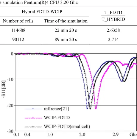
[image:5.595.313.534.277.382.2] [image:5.595.310.536.425.554.2] [image:5.595.321.527.605.715.2]Table 1. Comparison between the FDTD solution and the Hybrid FDTD-WCIP technique regarding the computational time for the different structure illustrated in this work.
Computer used for the simulation Pentium(R)4 CPU 3.20 Ghz
FDTD Method Hybrid FDTD-WCIP
Number of cells Time of the simulation Number of cells Time of the simulation
T_FDTD T_HYBRID
HP Filter 491,520 58 min 52 s 114688 22 min 20 s 2.6358
DRA antenna 1,966,080 243 min 03 s 90112 89 min 20 s 2.714
the first simulation with a regular discretization, The FDTD domain is 60 × 128 × 256 and the WCIP grid size is 128 × 256, and the cell size is Δx = 0.2 mm, Δy = 0.3125 mm, Δz = 0.35 mm.
Good agreements are observed in Figure 9 for the re-
sults of the reflection parameters between the hybrid me- thod and the FDTD method [21], which verified the ac- curacy of the proposed hybrid method.
Let us now consider the computational cost of the Hy- brid FDTD-WCIP method, comparing it with the con- ventional FDTD method in Table 1.
Even for more general structures with several different kinds of layers, the memory requirement for the present method is much smaller than that for the other hybrid FDTD methods [22].
Figure 9. Comparison of the results obtained by the pro- posed hybrid method with the FDTD simulation results.
It should be noted that, although the hybrid algorithm (FDTD-WCIP) is totally stable, but this approach suffer from the reduced of accuracy and computational effi- ciency when increasing the frequency, due to the inhere- rent discretization imposed by the WCIP Method.
much more facility in modelling of the structures and especially to make simulation with a minimum of time. We succeeded in formulating a three-dimensional and fast numerical method.
A hybrid FDTD-WCIP method is implemented in this letter using an iterative solution approach. Numerical results show that the hybrid method is accurate and effi- cient especially in terms of memory usage.
We show that the accuracy can be greatly improved by using a higher number of cells in the contact surface S between the two domains, complying with condition im- posed by the WCIP method. So to increase the number of cell must satisfy both conditions:
REFERENCES
The accuracy condition in the WCIP method requires that the cell size must be less than λ/50, which increases the number of cells in three dimensional domain and gradu- ally increases the computation time and cost memory.
[1] S. Wane, D. Bajon and H. Baudrand, “A New Full-Wave Hybrid Differential-Integral Approach for Investigation of Multilayer Structures Including Nouniformly Doped Diffusions,” IEEE Transactions on Microwave Theory
and Techniques, Vol. 3, No. 53, 2005, pp. 200-214.
Second is there must be a number of cell in the WCIP domain(in the xy plane) of the order of P = 2 ^ n, which is forcing us to round each time the number of cell in the
xy plane by a value above or below the value that satisfy the discretization developed by the FDTD method.
[2] N. Sboui, L. Latrach, A. Gharsallah, H. Baudrand and A. Gharbi, “A 2D Design and Modeling of Micro Strip Struc- tures on Inhomogeneous Substrate,” Wiley Interscience, New York, 2008.
These two conditions that promote the divergence of this method in the high frequency. To solve this problem we propose to develop a hybrid method with an irregular mesh, which can limit the divergence constraints on the conditions of the discretization in the WCIP method.
[3] M. Glaoui, H. Zairi and H. Trabelsi, “A New Computa- tionally Efficient Hybrid fdtLM-WCIP Method,” Interna-
tional Journal of Electronic, Vol. 96, No. 5 2009, pp. 537-
548.
[4] E.-X. Liu, E.-P. Li and L.-W. Li, “Analysis of Multilayer Planar Circuits by a Hybrid Method,” IEEE MicrowaveThe-
ory andWireless Component Letters, Vol. 16, No. 2, 2006,
pp. 66-68.
4. Conclusions
It is estimated whereas we will solve many problems by
[image:6.595.307.537.117.350.2]on Iterative Method,” International Journal of RF and
Microwave Computer—Aided Engineering, Vol. 13, No.
4, 2003, pp. 269-275. doi:10.1002/mmce.10084
[6] A. Taflove and M. E. Brodwin, “Numerical Solution of Steady-State Electromagnetic Scattering Problems Using the Time-Dependent Maxwell Equations,” IEEE Trans-
actions on Microwave Theory and Techniques, Vol. 23,
No. 8, 1975, pp. 623-630. doi:10.1109/TMTT.1975.1128640
[7] K. S. Kunz and R. J. Luebbers, “The Finite Difference Time Domain Method for Electromagnetics,” CRC Press, Boca Raton, 1993.
[8] M. Titaouine, A. G. Neto, H. Baudrand and F. Djahli, “Ana- lysis of Frequency Selective Surface on Isotropic/Ani- sotropic Layers Using WCIP Method,” ETRI Journal, Vol. 29, No. 1, 2007, pp. 36-44.
doi:10.4218/etrij.07.0106.0123
[9] M. A. Mangoud, R. A. Abd-Alhameed and P. S. Excell, “Simulation of Human Interaction with Monbile Tele- phones Using Hybrid Techniques over Coupled Domains,”
IEEE Transactions on Microwave Theory and Techniques,
Vol. 48, No. 11, 2000, pp. 2014-2021. doi:10.1109/22.884190
[10] M. Al Sharkawy, V. Demir and A. Z. Elsherbeni, “The Iterative Multi-Region Algorithm Using a Hybrid Finite Difference Frequency Domain and Method of Moment Techniques,” Progress in Electromagnetics Research, Vol. 57, 2006, pp. 19-32. doi:10.2528/PIER05071001
[11] D. Koh, H.-B. Lee and T. Itoh, “A Hybrid Full-Wave Analysis of Via-Hole Grounds Using Finite-Difference and Finite-Element Time-Domain Methods,” IEEE Trans-
action on Microwave Theory and Techniques, Vol. 45, No.
12, 1997, pp. 89-92.
[12] G. Ramzi, Z. Hassen, H. Trabelsi and H. Baudran, “Tun- ble Lowpass Filters Using Folded Slot Eteched in the Ground Plan,” Progress in Electromagnetics Research C, Vol. 7, 2009, pp. 65-78. doi:10.2528/PIERC09012706 [13] F. Lacroux and B. Jecko, “Contribution à la Modélisation
D’éléments Localisés Pour les Simulations Electro- magnétiques en Transitoire. Application en Millimétrique et au Transport D’énergie Sans Fil,” Thesis, Limoges University, Limoges, 2005.
[14] J. García-García, J. Bonache and M. Ferran “Application of Electromagnetic Bandgaps to the Design of Ultra-Wide
Bandpass Filters with Good Out-of-Band Performance,” Progress in Electromagnetics Research Symposium, Sin- gapore, 2003.
[15] E.-X. Liu, E.-P. Li and L.-W. Li, “Analysis of Multilayer Planar Circuits by a Hybrid Method,” IEEE Microwave
Theory and Wireless Component Letters, Vol. 16, No. 2,
2006.
[16] R. A. Abd-Alhameed, P. S. Excell, J. A. Vaul and M. A. Mangoud, “Computation of Radiated and Scattered Fields Using Separate Frequency Domain Moment-Method Re- gions and Frequency-Domain MOM-FDTD Hybrid Me- thods,” Proceedings of IEEE Conference Antennas and
Propagation, York, 31 March-1 April 1999, pp. 53-56.
[17] W. Thiel, K. Sabet and L. P. Katehi, “A Hybrid Mom/ FDTD Approach for an Efficient Modelling of Complex Antennas on Mobile Platforms,” Proceedings of the Euro-
pean Microwave Conference, 7-9 October 2003, pp. 719-
722.
[18] Z. Huang, K. R. Demarest and R. G. Plumb, “An FDTD/ MOM Hybrid Technique for Modelling Complex Anten- nas in the Presence of Heterogeneous Grounds,” IEEE
Transactions on Geoscience and Remote Sensing, Vol. 37,
No. 6, 1999, pp. 2692-2698. doi:10.1109/36.803416 [19] E. X. Liu, E.-P. Li and L.-W. Li, “Hybrid FDTD-MPIE
Method for the Simulation of Locally Inhomogeneous Mul- tilayer LTCC Structure,” IEEE Microwave and Wireless
Components Letters, Vol. 15, No. 1, 2005, pp. 42-44.
doi:10.1109/LMWC.2004.840981
[20] S. Mochizuk, S. Watanabe, M. Taki and Y. Yamanaka, “A New Hybrid MOM/FDTD Method for Antennas Lo- cated off the Yee’s Lattice,” 2004 URSI EMTS, Interna-
tional Symposium on Electromagnetic Theory, Pisa, 23-
27 May 2004, pp. 436-438.
[21] R. K. Mongia and A. Ittipiboon, “Theoretical and Experi- mental Investigations on Rectangular Dielectric Resona- tor Antennas,” IEEE Transactions on Antennas and Pro-
pagation, Vol. 45, No. 9, 1997, pp. 1348-1356.
doi:10.1109/8.623123
[22] H. Rogier, F. Olyslager and D. De Zutter, “A New Hybrid FDTD-BIE Approach to Model Electromagnetic Scatter- ing Problems,” IEEE Microwave and Wireless Compo-
nents Letters, Vol. 8, No. 3, 1998, pp. 138-140.