Developing an autopilot for the
peregrine falcon Robird
W. (Wessel) Straatman
MSc Report
Committee: Prof.dr.ir. S. Stramigioli Ir. G.A. Folkertsma Prof.dr.ir. H.W.M. Hoeijmakers N. Nijenhuis, BSc
October 2014
Developing an autopilot for the peregrine falcon Robird
Wessel Straatman∗, Gerrit A. Folkertsma∗, Nico Nijenhuis†, Stefano Stramigioli∗
∗ Robotics and Mechatronics group, CTIT institute, University of Twente
[email protected], [email protected], [email protected]
† Clear Flight Solutions, Enschede, The Netherlands [email protected]
Abstract— In this paper, we introduce an autopilot for the peregrine falcon Robird, a robotic bird of prey. Currently, piloting the Robird is very difficult and operator intensive. The effect of flapping-wing flight on measurement data and flight stability is investigated. A gliding controller, an algorithm that takes care of transition between flight modes, is also introduced. The autopilot is implemented in the form of controllers for roll and pitch. As a result, the operator’s cognitive load is decreased and the Robird keeps itself stable when no remote control inputs are given. This is a first step towards completely autonomous flight of the Robird.
I. INTRODUCTION
Birds can be a nuisance when present in large numbers in utilitarian areas such as airports, farms and rural areas. They form a hazard to planes or spread diseases. Present-day pest control solutions vary from visual deterrents (the old-fashioned scarecrow) to more violent methods like the use of chemicals or weapons [1]. However, birds often easily adapt to static bird control methods like visual deterrents; and pub-lic opinion considers violent approaches to be unnecessarily cruel. A possible solution lies in the use of bird-like flying robots that mimic predators and act as a natural deterrent for pest birds.
Nature has always been a source of inspiration for re-search, especially for the field of robotics. Here, the desire to understand and mimic nature has resulted in an increasing amount of biologically inspired robots, like the MIT Cheetah robot [3], the RoboFish from the University of Singapore [4] and the LittleApe robot [5]. For aerial robotics this has proven to be rather complicated, since flapping-wing motion is very difficult to accurately model, understand and reproduce. Researchers working on insect-based flapping-wing aerial vehicles, such as the DelFly MAV from Delft University of Technology [6], Harvard’s RoboBee [7] or the beetle-inspired MAV [8], focus mostly on indoor applications and therefore aim to be lightweight, small and capable of low-speed indoor flight. The lightweight Golden Snitch MAV [9], inspired by the fictional Golden Snitch from the Harry Potter novels, has similar characteristics. Larger biologically inspired aerial vehicles, based on birds, are for example the SmartBirds from Festo [10]. Whilst Festo has achieved realistic flapping-wing motion that mimics the kinematics of actual bird flight, its lightweight structure still makes it
(a) An actual peregrine falcon [2].
[image:2.595.333.514.245.503.2](b) The peregrine falcon Robird.
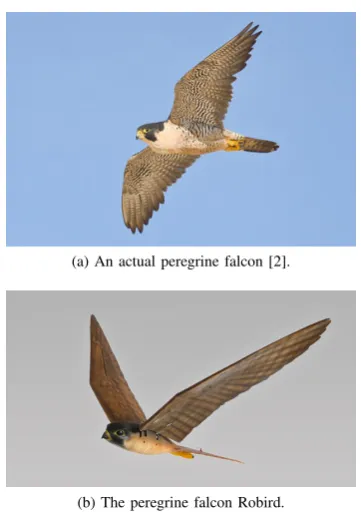
Fig. 1. A comparison between a peregrine falcon (a) and its robotic counterpart (b).
hard to fly outdoors due to an inability to properly deal with external disturbances like wind.
This makes wide-scale use of the Robirds for bird control unfeasible at this moment. In this paper we therefore present the development of an autopilot for the peregrine falcon robot. An autopilot will assist the operator in flying the robot, while for safety reasons never excluding the human’s ability to switch back to manual control. In autopilot mode, the robot is expected to stabilize its roll and pitch, while leaving control of speed, altitude and direction to the operator. The control algorithm is implemented for two flight modes: flapping-wing mode and gliding mode. The goal is to make it easier for a Robird operator to control the bird, and work towards increasing the autonomy of the Robirds.
II. THE PEREGRINE FALCONROBIRD
This work focusses on the peregrine falcon Robird model. Peregrine falcons are bird-eating birds of prey, having a wingspan of95 to 115 cm and a body length of 39to 50 cm [12]. Their weight varies, depending on e.g. sex and season, from 600 to 1300 g. The peregrine falcon is the
fastest animal known to men: the highest measured speed a peregrine falcon has reached during a hunting stoop is over350 km h−1. Peregrine falcons hunt over 1500 different species of birds worldwide, making it one of the most diverse predators. All this makes for a very suitable bird to mimic for successful bird control using the Robirds.
A. The Robird
The peregrine falcon Robird model is of comparable size and weight to an actual peregrine falcon: it has a total mass of approximately730 g; its wings, weighing70to75 geach,
provide a wingspan of112 cm. This results in a model that is able to realistically mimic an actual peregrine falcon’s physique and silhouette. The inner mechanism to which the wings are connected generates a wave-like flapping motion of the wing, providing both lift and thrust, thus allowing the Robird to fly in a realistic way: without the need for other propulsion such as propellors or engines. The Robirds have a flight control surface on each wing, allowing control of yaw and roll of the bird; and a servo-driven tail for pitch control. Fig. 1 shows the peregrine falcon model of the Robird next to an actual peregrine falcon.
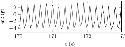
A big challenge in flying the Robird, when compared to a regular fixed-wing aircraft, is the force that the flapping-wing motion exerts on the body. It influences stability and adds a challenge for the operator when controlling the bird in manual mode, but in terms of an autopilot implementation it also influences sensor readings of e.g. aircraft attitude. Fig. 2 shows the measured acceleration in vertical direction for a peregrine falcon Robird flight. For this part of the flight— where throttle and altitude were kept approximately constant so as not to apply additional forces in vertical direction—the flapping-wing frequency is between5.5 and6 Hz and, as a
result, the body experiences accelerations of up to3g due to the wing motion.
170 171 172 173
−4 −2 0 2 t (s) acc (g)
Fig. 2. Acceleration in vertical direction during flapping-wing flight. The flapping-wing frequency can clearly be identified from the signal, and the high-frequency behaviour of the acceleration is dominated by the flapping-wing forces.
B. The APM platform and ArduPilot codebase
The brain of the Robird consists of the ArduPilot Mega (APM) 2.6 board. The APM 2.6 features an ATMEGA2560 processor chip and several on-board sensors. The board has a 3-axis gyroscope plus accelerometer and a barometric pressure sensor for state estimation. An on-board Dataflash chip allows for logging of flight data and easy post-flight analysis of the bird’s performance.
The board is compatible with Arduino [13], making it easy to program. The firmware is based on the ArduPilot ArduPlane open-source software base [14]. Several modifi-cations and additions have been made to port the software from working on a model airplane towards working on a bird propelling itself using flapping-wing motion.
Besides the on-board sensors there is also room for adding an angular encoder to measure wing position (required for gliding mode), an airspeed sensor and a GPS.
III. FLIGHT MODES
The Robirds have two different flight modes: the first is the aforementioned flapping-wing mode, where the Robird beats its wings to control airspeed and gain altitude; the second is the so-called gliding mode. In gliding mode, a passive lock holds the wings in a fixed position, allowing the bird to soar through the air without the use of motor power. Since the Robird has no means of propulsion during gliding mode, gliding is especially useful to travel from a point at higher altitude to a lower altitude point in a smooth and energy-efficient manner. The wing angle (see Fig. 10) is measured using an angular encoder, and a smart software implementation ensures that the bird switches from flapping-wing to gliding mode at the correct time (see section III-B “Gliding Mode”).
A. Flapping-wing mode
[image:3.595.316.530.87.168.2]0 5 10 15 20
frequency (Hz)
signal
po
[image:4.595.315.536.83.271.2]wer
Fig. 3. Single-sided amplitude spectrum of acceleration measurement taken during Robird flight. A clear peak in the spectrum is present at the flapping-wing frequency, with smaller peaks at its higher harmonics.
60 70 80 90 100
4 4.5 5 5.5 6
throttle percentage
frequenc
y
(Hz)
Fitted curve Data points
Fig. 4. Relation between flapping-wing frequency and throttle: measure-ments obtained from power spectra such as Fig. 3, and a fitted curve. The data is fit on the basis of a least squares quadratic fit algorithm.
solution for the flapping-wing motion disturbance on the state estimation. By investigating the power spectrum of measurement data taken at constant throttle, the flapping-wing frequency is determined. A typical power spectrum is given in Fig. 3: the flapping-wing frequency corresponding to that throttle value can be determined from the clear peak in the spectrum. Using a least squares fit algorithm, the curve of Fig. 4 is obtained from a series of spectra obtained at various throttle values.
With this throttle-frequency relation, a tuned notch filter could be used to filter out the disturbance signal. However, the influence of e.g. airspeed on wing frequency is yet unknown, so a low-pass filter with a cut-off frequency of
2 Hz is used instead. Fig. 5 shows a filtered pitch data set compared to the original data. This filtering was done on the logged data and has yet to be implemented on the code running on-board.
For state estimation the filtering seems desirable, since we are mainly interested in the state evolution across wing strokes, and not in the high-frequency in-stroke deviations. However, filtering out the high frequent pitch variation also disables the ability of the pitch controller to respond to it: this gets rid of the fast tail motion that counteracts the flapping-wing motion. Besides adversely influencing flight stability, high speed videos of bird flight suggest that actual birds also use their tail to compensate for flapping-wing forces, as can be seen in Fig. 6—so removing that motion from the Robird also makes them less true-to-life.
110 120 130 140 150 160 170
0 10 20 30 40
t (s)
angle
(de
g)
Actual pitch Low pass filtered
[image:4.595.65.281.86.193.2]Fig. 5. Actual unfiltered pitch angles compared to a filtered data set.
Fig. 6. Two stills from a high speed recording of hummingbird flight, demonstrating the use of the tail to counteract flapping-wing forces and remain stable [15].
B. Gliding mode
When the Robird is at a high altitude, the operator can choose to switch from flapping-wing to gliding mode. In gliding mode the wings are fixed, thereby essentially chang-ing the vehicle from a flappchang-ing-wchang-ing aircraft to a fixed-wchang-ing glider. Gliding is an energy efficient way of moving through the air, mimicking a real bird of prey’s soaring.
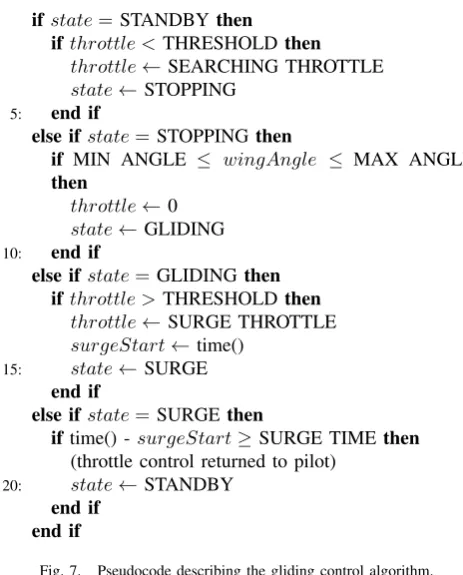
The switch from flapping-wing mode to gliding mode is performed by the gliding controller. The algorithm is shown in pseudocode in Fig. 7 and depicted by the finite state machine of Fig. 8. In short, the Robird switches to gliding mode whenever the pilot moves the throttle below a certain threshold, going back to flapping-wing flight when the throttle clears the threshold again. Fig. 9 illustrates this by showing requested throttle versus actual supplied throttle: between t=25 sand t=32 sthe Robird is in gliding mode and
the pilot has no direct control over the throttle of the Robird.
[image:4.595.55.289.243.365.2] [image:4.595.305.542.304.387.2]ifstate= STANDBYthen
ifthrottle <THRESHOLDthen
throttle←SEARCHING THROTTLE
state←STOPPING
5: end if
else ifstate=STOPPING then
if MIN ANGLE ≤ wingAngle ≤ MAX ANGLE
then
throttle←0
state←GLIDING 10: end if
else ifstate=GLIDINGthen
ifthrottle >THRESHOLDthen
throttle←SURGE THROTTLE
surgeStart←time()
15: state←SURGE
end if
else ifstate=SURGEthen
iftime() -surgeStart≥SURGE TIMEthen
(throttle control returned to pilot) 20: state←STANDBY
end if end if
Fig. 7. Pseudocode describing the gliding control algorithm.
Standby
Stopping
Gliding Surge
throttle<THRESHOLD
throttle>THRESHOLD time()-surgeStart>SURGEUTIME
MINUANGLEU≤UwingAngleU
[image:5.595.53.285.82.370.2]≤UMAXUANGLE
Fig. 8. Finite state machine displaying gliding controller states and transition conditions. The “surge” state is required to pull the bird out of gliding mode, by supplying a high throttle for a short time.
15 20 25 30 35
0 20 40 60 80 100
Standby StoppingGliding Surge Standby
t (s)
throttle
percentage
Requested Supplied
Fig. 9. Demonstration of the working of the gliding controller. Requested throttle is the pilot-supplied input to the RC channel; the supplied throttle is the actual throttle that is sent to the motor. When the gliding controller is engaged, the software takes over throttle control.
MAX ANGLE
MIN ANGLE MAX ANGLE
MIN ANGLE θ
Fig. 10. Illustration of maximum and minimum wing angles for switching into gliding mode. The wing has to be in downstroke to switch to gliding mode, for the passive lock to engage. The angleθis defined as the wing angle.
Fig. 11. Passive lock mechanism used to lock the wings in gliding mode. The wheel is attached to the driving shaft of the wings. The arrow indicates rotational direction during flapping-wing motion and the shaded area shows the minimum and maximum angle to stop, as illustrated in Fig. 10.
IV. CONTROL
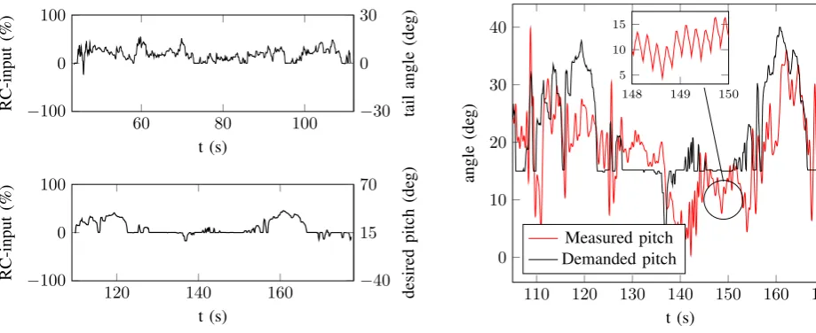
The implemented controller works in so-called “Fly-by-Wire A” (FBWA) mode. In FBWA, the roll and pitch of the bird are controlled, whilst the operator still has full control over the throttle. In manual mode, a remote control (RC) input to the roll and pitch channels directly controls the wing and tail flaps, respectively. In FBWA mode, however, the RC input is translated to an angle setpoint and the Robird stabilises itself—as opposed to manual mode, where active pilot control is required to stabilize the flight of the Robird. The goal of the implemented autopilot mode is to make it easier and less operator-intensive to fly a Robird. Fig. 12 shows that the implemented controller indeed achieves this goal: operator RC input is shown for both manual and FBWA flight. The upper plot shows the constant need to compensate for flapping-wing motion. Conversely, in FBWA mode the controller takes care of this, relieving the operator of this task. The pitch in FBWA mode has an offset of15◦because the Robird must fly with a slightly tilted body. In manual mode, the pilot has to maintain this tilt manually through a constant offset in tail deflection.
A. Flapping-wing mode
[image:5.595.305.540.95.188.2] [image:5.595.302.543.247.352.2] [image:5.595.55.283.380.495.2] [image:5.595.55.290.539.704.2]60 80 100 −100 0 100 t (s) RC-input (%) −30 0 30 tail angle (de g)
120 140 160
−100 0 100 t (s) RC-input (%) −40 15 70 desired pitch (de g)
Fig. 12. Comparison of operator commands between manual (above) and fly by wire (below) mode. The left axis shows operator RC input for the tail; the right the corresponding tail deflection for manual mode and desired pitch for fly by wire mode, respectively.
110 120 130 140 150 160 170
−50 0 50 t (s) angle (de g) Measured roll Demanded roll
Fig. 13. Demanded roll versus actual roll angles for flapping-wing flight. Demanded roll is a function of the RC input given by the pilot.
input the pilot gives on the RC transmitter, versus measured roll. Fig. 14 shows the same plot, but for pitch angles.
The PD controller does not achieve perfect setpoint regu-lation, due to complicated (high-order) flight dynamics and external disturbances. However, the attitude control of FBWA is an inner control loop with the pilot in a slower outer loop, who will compensate for these disturbances. Considering that the end goal from the pilot’s point of view is not achieving a certain roll or pitch angle, but instead achieving a turn towards the left or right, or an increase or decrease in altitude, this is not considered to be a problem.
B. Gliding mode
The controller was also applied to a gliding flight, with the same control parameters as for the flapping-wing flight. In this flight, the bird landed while in gliding mode.
The difference between flight modes is that the measured signal is a much cleaner signal in gliding mode, due to
110 120 130 140 150 160 170
0 10 20 30 40 t (s) angle (de g) Measured pitch Demanded pitch
148 149 150 5
10 15
Fig. 14. Demanded pitch versus actual pitch angles (filtered) for flapping-wing flight. Demanded pitch is a function of the RC input given by the pilot. Inset: unfiltered pitch angles showing flapping-wing frequency.
590 591 592 593 594 595
[image:6.595.318.536.85.271.2]−2 0 2 t (s) acc z (g)
Fig. 15. Acceleration in vertical direction during the transition from flapping-wing to gliding flight. The decrease in flapping-wing frequency is evident in the signal, and the decreasing magnitude shows that the experienced accelerations by the body are indeed due to flapping-wing flight.
[image:6.595.56.516.86.274.2]the absence of flapping-wing influences. Fig. 15 shows an acceleration measurement at the moment of transitioning into gliding mode, from which the difference in measurement signals is clearly noticeable.
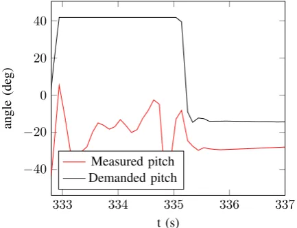
Fig. 16 shows the performance of the roll controller in gliding mode. Again, the delay in controller action due to the flight dynamics is clearly distinguishable. The performance of the pitch controller shows that it is more difficult to control pitch in gliding mode, especially when flying at a low airspeed, as can be seen in Fig. 17. Due to the bird’s mass distribution it has a tendency to pitch down, especially at low airspeed. In order to compensate for this, the Robird pilot has to constantly demand a pitch up in order to ensure a smooth, flat landing.
V. CONCLUSION ANDOUTLOOK
[image:6.595.54.293.88.269.2] [image:6.595.309.541.321.402.2] [image:6.595.67.280.327.496.2]333 334 335 336 337 −50 0 50 t (s) angle (de g) Measured roll Demanded roll
Fig. 16. Demanded roll versus actual roll angles for a landing in gliding mode. After t=335 sthe Robird has landed. Demanded roll is a function of the RC input given by the pilot.
333 334 335 336 337
−40 −20 0 20 40 t (s) angle (de g) Measured pitch Demanded pitch
Fig. 17. Demanded pitch versus actual pitch angles for a landing in gliding mode. After t=335 sthe Robird has landed. Demanded pitch is a function of the RC input given by the pilot.
each of the two Robird flight modes: flapping-wing mode and gliding mode.
For the Robird to acquire more autonomy, several steps have to be taken. By adding a GPS sensor, and optionally also an airspeed sensor, it is possible to also hand over throttle control to the on-board computer. The next step in development is therefore that the Robirds are able to fly to a certain waypoint, or circle around a given location autonomously, while exploiting its clever flying techniques by switching between flapping-wing and gliding mode.
Furthermore, in order to improve upon the roll and pitch controller designs, a dynamic model of the flapping-wing vehicle is a necessity. Wind tunnel experiments are being performed, so that several important flight characteristics and coefficients of the Robird can be determined. With this dynamic model, controller tuning can move from operator perception based tuning to actual performance-based optimi-sation in accurate simulations.
In order to further improve upon flight performance of the Robird, developments on the hardware are also being made. Important characteristics for flight behaviour are the total mass and mass distribution. Currently, at 730 g the Robird is near its maximum takeoff weight (MTOW). The goal is to further decrease the mass of the Robird to approximately
700 g, by using a lighter material for the Robird body and redesigning the inner mechanism. For in-flight stability of the Robird, the location of the center of mass is of vital importance. Ideally, the center of mass lies right between the two attachment points of the wings. Currently, the center of mass lies more towards the tail. Therefore, when decreasing the total mass of the Robird, the goal is to remove more mass from the back of the bird and, if possible, add more mass in the front.
Finally, now that the Robird is easier to fly, more tests can be performed on waste management facilities, airports and farms, to further investigate the effects that the Robirds have on the behaviour of the nuisance birds.
REFERENCES
[1] A. E.-A. S. S. Desoky, “A review of bird control methods at airports,”
Global Journal of Science Frontier Research, vol. 14, no. 2, 2014. [2] (2014, Aug.) All about birds. The Cornell Lab of Ornithology.
[Online]. Available: http://www.allaboutbirds.org
[3] S. Seok, A. Wang, M. Y. M. Chuah, D. Otten, J. Lang, and S. Kim, “Design principles for highly efficient quadrupeds and implementation on the mit cheetah robot,” inProc. IEEE International Conference on Robotics and Automation, Karlsruhe, Germany, 2013, pp. 3307–3312. [4] A. Chowdhury, B. Prasad, V. Vishwanathan, R. Kumar, and S. Panda, “Kinematics study and implementation of a biomimetic robotic-fish underwater vehicle based on lighthill slender body model,” in Au-tonomous Underwater Vehicles (AUV), 2012 IEEE/OES, Sept 2012, pp. 1–6.
[5] D. Kuhn, M. Rommermann, N. Sauthoff, F. Grimminger, and F. Kirch-ner, “Concept evaluation of a new biologically inspired robot littleape,” inIntelligent Robots and Systems, 2009. IROS 2009. IEEE/RSJ Inter-national Conference on, Oct 2009, pp. 589–594.
[6] M. Groen, B. Bruggeman, B. Remes, R. Ruijsink, B. van Oudheusden, and H. Bijl, “Improving flight performance of the flapping wing mav delfly ii,” inInternational Micro Air Vehicle conference and competitions, 2010.
[7] Z. E. Teoh, S. B. Fuller, P. Chirarattananon, N. O. Perez-Arancibia, J. D. Greenberg, and R. J. Wood, “A hovering flapping-wing mi-crorobot with altitude control and passive upright stability,” inProc. IEEE/RSJ International Conference on Intelligent Robots and Systems, Vilamoura, Algarve, Portugal, 2012, pp. 3209–3216.
[8] N. S. Ha, Q. T. Truong, H. V. Phan, N. S. Goo, and H. C. Park, “Structural characteristics of allomyrina dichotoma beetle’s hind wings for flapping wing micro air vehicle,”Journal of Bionic Enginering, vol. 11, pp. 226–235, 2014.
[9] F.-Y. Hsiao, L.-J. Yang, S.-H. Lin, C.-L. Chen, and J.-F. Shen, “Autopilots for ultra lightweight robotic birds,”IEEE Control Syst. Mag., pp. 35–48, 2012.
[10] (2014, Aug.) Smartbird - bird flight deciphered. Festo. [Online]. Available: http://www.festo.com/cms/en corp/11369.htm
[11] (2014, Aug.) Clear Flight Solutions. [Online]. Available: http://www.clearflightsolutions.com
[12] P. Hayman and R. Hume,Alle vogels van Europa (translation from: Bird : the ultimate illustrated guide to the birds of Britain and Europe). Baarn, The Netherlands: Tirion Natuur, 2008.
[13] (2014, Sep.) Arduino website. Arduino. [Online]. Available: http://arduino.cc/
[14] (2014, Aug.) Multiplatform autopilot. ArduPilotMega. [Online]. Available: http://www.ardupilot.com
[image:7.595.63.280.84.255.2] [image:7.595.63.280.305.471.2]APPENDIXA: SOFTWARE CHANGES
To port the ArduPlane firmware to a working version of ArduBird, rename ArduPlane.pde to ArduBird.pde, and add RobirdGlidingController.h, RobirdGlidingController.pde, RobirdParameters.h, RobirdRC_ThrottleChannel.cpp and RobirdRC_ThrottleChannel.h to the folder. Also, for the simple reason of storage limits on the APM board, remove the filetest.pde. The changes are related to the following:
1) Read the angular encoder for wing position sensing
2) Call the custom throttle channel that uses the gliding controller 3) Make the software work with the multiple aileron setup of the Robird 4) Allow for Robird specific datalogging
5) For storage limits reasons, get rid of unnecessary code
The codebase referenced can be found in the git repository located athttps://git.ce.utwente.nl/robird, and the revision at the moment of writing is taggedMScThesis.
Changes in ArduBird.pde
• [1,2] Include the following header files:
#include "RobirdRC_ThrottleChannel.h"
#include "RobirdGlidingController.h"
#include "RobirdParameters.h"
#include <avr/interrupt.h>
• [1] Add the define:
#define PWM_AS5045 (PINK & 0x01) // connects to pin A8
• [1,2] Declare the following variables:
const int asPin = 8;
uint32_t robird_timer_millis;
volatile uint32_t pulse_start_us, pulse_end_us;
volatile uint16_t pulse_length;
RobirdRC_ThrottleChannel channel_throttle_actual(rcmap.throttle()-1);
• [1] Define the interrupt service routine (ISR), preferably just before the setup() method for clarity:
ISR(PCINT2_vect){
if(PWM_AS5045){
// The pin has just changed to HIGH
pulse_start_us = hal.scheduler->micros(); } else {
// The pin has just changed to LOW
pulse_end_us = hal.scheduler->micros();
pulse_length = (pulse_end_us-pulse_start_us); }
}
• [1,2] Set up the angular encoder and gliding controller by adding the following to the setup() method:
// Initialise the pin
hal.gpio->pinMode(hal.gpio->analogPinToDigitalPin(asPin), HAL_GPIO_INPUT);
// Set up interrupt uint8_t oldSREG = SREG; cli();
PCMSK2 |= _BV(PCINT16); PCICR |= _BV(PCIE2); SREG = oldSREG;
• [4] Enable Robird data logging by addingLog_Write_Bird();to the methodupdate_logging2(void). • [3] Enable the ability to control the left and right wing ailerons separately:
Replace
nav_roll_cd = channel_roll->norm_input() * roll_limit_cd;
by
int16_t chroll_above_trim = channel_roll->radio_in - channel_roll->radio_trim;
int16_t chauxroll_under_trim = RC_Channel_aux::dist_from_trim();
if (chroll_above_trim > chauxroll_under_trim) {
nav_roll_cd = channel_roll->norm_input() * roll_limit_cd; } else {
nav_roll_cd = RC_Channel_aux::norm_input_ch() * roll_limit_cd; }
• [4] Add a method to ask for the pulse length, for data logging purposes:
uint16_t get_pulse_length(){
return pulse_length; }
Changes in Log.pde
• [4] To properly log Robird specific data add the following:
struct PACKED log_Bird { LOG_PACKET_HEADER;
uint32_t timestamp;
uint32_t rotation_log;
float frequency_log;
uint8_t gc_state_log;
uint16_t angle_log;
uint16_t curThrottle_log;
int32_t roll_reference;
int32_t pitch_reference; };
// Write a Robird Log packet static void Log_Write_Bird(void) {
struct log_Bird pkt = {
LOG_PACKET_HEADER_INIT(LOG_BIRD_MSG), timestamp : hal.scheduler->millis(),
rotation_log : (uint32_t)get_rotationCount(), frequency_log : get_wingFrequency(),
gc_state_log : get_gc_state(), angle_log : get_wingAngle(),
curThrottle_log : get_curThrottle(), roll_reference : nav_roll_cd,
pitch_reference : nav_pitch_cd };
DataFlash.WriteBlock(&pkt, sizeof(pkt)); }
• [4] Add the Robird log structure to thelog_structure PROGMEM: {LOG_BIRD_MSG,sizeof(log_Bird),
• [4] Add the dummy function for the Robird log method to the list of dummy functions near the end:
static void Log_Write_Bird(void) {}
Changes in defines.h
• [4] AddLOG_BIRD_MSGat the end of the enum list of log messages.
Changes in radio.pde
• [2] Make sure the throttle channel is our custom made throttle channel: Replace
channel_throttle = RC_Channel::rc_channel(rcmap.throttle()-1);
by
channel_throttle = &channel_throttle_actual;
and replace
channel_throttle->set_range(0,100);
by
channel_throttle->set_range(0,125);
Changes in system.pde
• [5] Remove the following three lines that are calling for methods fromtest.pde:
– static int8_t test_mode(uint8_t argc, const Menu::arg *argv); //in test.cpp
– " test test mode\n"
– {"test", test_mode},
Changes in test.pde
• [5] Removetest.pde
Changes in the ArduPilot libraries
Please note that it is advised to not change the native libraries, unless absolutely necessary.
• InAP_Rally.cpp, add the following to theAPM_BUILD_DIRECTORYconditional definition:
#elif APM_BUILD_TYPE(APM_BUILD_ArduBird)
#define RALLY_LIMIT_KM_DEFAULT 5.0
• InAP_Vehicle.h, add the ArduBird vehicle build type define to the common build types:
#define APM_BUILD_ArduBird 10
• [2] In RC_Channel.h, all functions and variables should be made virtual, to allow for inheritance in our custom throttle channel.
• [3] InRC_Channel_aux.h, define the following methods:
// get the norm input for an auxiliary channel static float norm_input_ch();
And implement the methods inRC_Channel_aux.cpp:
float RC_Channel_aux::norm_input_ch() {
float ret=0;
int8_t reverse=1;
for (uint8_t i = 0; i < RC_AUX_MAX_CHANNELS; i++) {
if (_aux_channels[i] == NULL) continue;
RC_Channel_aux::Aux_servo_function_t function =...
(RC_Channel_aux::Aux_servo_function_t)_aux_channels[i]->function.get();
switch (function) {
case RC_Channel_aux::k_flap:
case RC_Channel_aux::k_flap_auto:
case RC_Channel_aux::k_flaperon1:
case RC_Channel_aux::k_flaperon2:
case RC_Channel_aux::k_egg_drop:
case RC_Channel_aux::k_aileron:
case RC_Channel_aux::k_aileron_with_input:
if(_aux_channels[i]->get_reverse()){ reverse = -1;
} else{
reverse = 1; }
if(_aux_channels[i]->radio_in < _aux_channels[i]->radio_trim) { ret = reverse * (float)(_aux_channels[i]->radio_in -...
_aux_channels[i]->radio_trim)/(float)(_aux_channels[i]->radio_trim -... _aux_channels[i]->radio_min);
} else{
ret = reverse * (float)(_aux_channels[i]->radio_in -...
_aux_channels[i]->radio_trim)/(float)(_aux_channels[i]->radio_max -... _aux_channels[i]->radio_trim);
}
break;
case RC_Channel_aux::k_elevator:
case RC_Channel_aux::k_elevator_with_input:
case RC_Channel_aux::k_dspoiler1:
case RC_Channel_aux::k_dspoiler2:
case RC_Channel_aux::k_rudder:
case RC_Channel_aux::k_steering:
default:
break; }
}
return constrain_float(ret, -1.0f, 1.0f); }
int16_t RC_Channel_aux::dist_from_trim() {
int16_t ret=0;
for (uint8_t i = 0; i < RC_AUX_MAX_CHANNELS; i++) {
if (_aux_channels[i] == NULL) continue;
RC_Channel_aux::Aux_servo_function_t function =...
switch (function) {
case RC_Channel_aux::k_flap:
case RC_Channel_aux::k_flap_auto:
case RC_Channel_aux::k_flaperon1:
case RC_Channel_aux::k_flaperon2:
case RC_Channel_aux::k_egg_drop:
case RC_Channel_aux::k_aileron:
case RC_Channel_aux::k_aileron_with_input:
ret = _aux_channels[i]->radio_trim - _aux_channels[i]->radio_in;
break;
case RC_Channel_aux::k_elevator:
case RC_Channel_aux::k_elevator_with_input:
case RC_Channel_aux::k_dspoiler1:
case RC_Channel_aux::k_dspoiler2:
case RC_Channel_aux::k_rudder:
case RC_Channel_aux::k_steering:
default:
break; }
}
return ret; }
Updating to the new ArduPlane firmware
![Fig. 6.Two stills from a high speed recording of hummingbird flight,demonstrating the use of the tail to counteract flapping-wing forces andremain stable [15].](https://thumb-us.123doks.com/thumbv2/123dok_us/9897715.491082/4.595.65.281.86.193/recording-hummingbird-ight-demonstrating-counteract-apping-andremain-stable.webp)